Table of Contents

Related Manuals for Moxa Technologies EDR-G9010 Series


Summary of Contents for Moxa Technologies EDR-G9010 Series
- Page 1 EDR-G9010 Series Quick Installation Guide Moxa Industrial Secure Router Version 1.1, September 2021 Technical Support Contact Information www.moxa.com/support 2021 Moxa Inc. All rights reserved. P/N: 1802090101012 *1802090101012*...
-
Page 2: Package Checklist
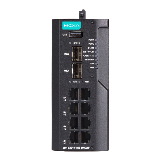
Package Checklist The EDR-G9010 Series, which is a secure router, is shipped with the items listed below. If any of these items are missing or damaged, please contact your customer service representative for assistance. • 1 Industrial secure router •... - Page 3 Panel Views of EDR-G9010 Series Front Panel Front Panel: 1. USB port for ABC-02-USB 2. 1G/2.5G SFP port speed LED indicator 3. 1G/2.5G SFP ports 4. 1G/2.5G SFP port speed LED indicator 5. 1000 Mbps copper port speed LED indicator 6.
-
Page 4: Mounting Dimensions
Rear Panel Rear Panel: 1. DIN-rail mounting kit Mounting Dimensions - 4 -... -
Page 5: Wall Mounting
DIN-rail Mounting (DNV-certified) In the package, the metal DIN-rail mounting kit is fixed to the back panel of the EDR-G9010 Series. Mount the EDR-G9010 Series on a corrosion-free mounting rail that adheres to the EN 60715 standard. Suggested Installation Method... -
Page 6: Wiring Requirements
STEP 2: Mounting the EDR-G9010 Series on the wall requires two M3 screws. Use the EDR-G9010 Series with the wall mount plates attached as a guide to mark the correct location of the two screws. The wall- mounting holes are marked A in the above diagram. - Page 7 ATTENTION Safety First! Be sure to disconnect the power cord before installing and/or wiring your EDR-G9010 Series. Calculate the maximum possible current in each power wire and common wire. Observe all electrical codes dictating the maximum current allowable for each wire size.
-
Page 8: Wiring The Redundant Power Inputs
Wiring the Redundant Power Inputs The EDR-G9010 Series has two sets of power inputs—power input 1 and power input 2. The top and side views of the terminal block connector are shown below. STEP 1: Use a small flat-blade screwdriver to press a wire locker. -
Page 9: The Reset Button
NOTE DO NOT power off the device when loading default settings. LED Indicators The front panel of the EDR-G9010 Series has several LED indicators. The function of each LED is described in the following table: - 9 -... -
Page 10: Specifications
The EDR-G9010 is not set as the Master of this Turbo Ring or is set as a Member of the Turbo Chain. The EDR-G9010 Series’ coupling function is enabled to form a backup path, or the device is set as the Tail of the Turbo Chain. -
Page 11: Standards And Certifications
Power Consumption 18.08 W (max.) Operating Temperature Standard models: -10 to 60°C (14 to 140°F) Wide-temp. models: -40 to 75°C (-40 to 167°F), DNV-certified for -25 to 70°C (-13 to 158°F) Storage Temperature -40 to 85°C (-40 to 185°F) Compass Safety Distance 35 cm WARNING 사...