GE 469 Instruction Manual
Motor management relay
Hide thumbs
Also See for 469:
- Instruction manual (348 pages) ,
- Manual (307 pages) ,
- Communications manual (150 pages)
Table of Contents
Advertisement
Quick Links
g
GE Multilin
215 Anderson Avenue, Markham, Ontario
Canada L6E 1B3
Tel: (905) 294-6222 Fax: (905) 294-8512
Internet: http://www.GEindustrial.com/multilin
Courtesy of NationalSwitchgear.com
MOTOR MANAGEMENT RELAY
Instruction Manual
469 Firmware Revision: 30E281.000
469PC Software Revision: 2.9x
Manual P/N: 1601-0057-DA (GEK-106289B)
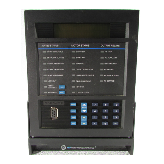
469 STATUS
MOTOR STATUS
OUTPUT RELAYS
SR469 IN SERVICE
STOPPED
SETPOINT ACCESS
STARTING
COMPUTER RS232
RUNNING
COMPUTER RS485
OVERLOAD PICKUP
AUXILIARY RS485
UNBALANCE PICKUP
LOCKOUT
GROUND PICKUP
RESET
HOT RTD
POSSIBLE
RESET
MESSAGE
LOSS OF LOAD
NEXT
PROGRAM PORT
7
SETPOINT
MESSAGE
4
ACTUAL
1
ESCAPE
VALUE
.
ENTER
469
Motor Management Relay®
GE Industrial Systems
469
Copyright © 2002 GE Multilin
R1 TRIP
R2 AUXILIARY
R3 AUXILIARY
R4 ALARM
R5 BLOCK START
R6 SERVICE
8
9
5
6
2
3
0
HELP
806766A5.CDR
®
Manufactured under an
ISO9001 Registered system.
Advertisement
Table of Contents

Related Manuals for GE 469


Summary of Contents for GE 469
- Page 1 GE Industrial Systems ® MOTOR MANAGEMENT RELAY Instruction Manual 469 Firmware Revision: 30E281.000 469PC Software Revision: 2.9x Manual P/N: 1601-0057-DA (GEK-106289B) Copyright © 2002 GE Multilin 469 STATUS MOTOR STATUS OUTPUT RELAYS SR469 IN SERVICE STOPPED R1 TRIP SETPOINT ACCESS...
- Page 2 Courtesy of NationalSwitchgear.com...
-
Page 3: Table Of Contents
TABLE OF CONTENTS 1. INTRODUCTION 1.1 OVERVIEW 1.1.1 Description ......................1-1 1.1.2 Order Information ....................1-3 1.2 SPECIFICATIONS 1.2.1 469 Specifications ....................1-4 2. INSTALLATION 2.1 MECHANICAL 2.1.1 Description ......................2-1 2.1.2 Product Identification..................2-2 2.1.3 Installation ......................2-3 2.1.4 Unit Withdrawal and Insertion ................ - Page 4 Current, KW, Kvar, and KVA Demand ..............4-68 4.12.4 Pulse Output .....................4-69 4.13 S12 ANALOG I/O 4.13.1 Analog Outputs 1 to 4 ..................4-71 4.13.2 Analog Inputs 1 to 4 ..................4-73 4.13.3 Analog In Diff 1-2 ....................4-75 469 Motor Management Relay GE Multilin Courtesy of NationalSwitchgear.com...
- Page 5 5.5.3 Timers ......................5-21 5.6 A5 EVENT RECORDER 5.6.1 Event 01 to Event 40..................5-22 5.7 A6 PRODUCT INFO 5.7.1 469 Model Information ..................5-24 5.7.2 Calibration Information ..................5-24 5.8 DIAGNOSTICS 5.8.1 Diagnostic Messages ..................5-25 5.8.2 Flash Messages ....................5-26 6.
- Page 6 Phase Current Accuracy Test ................7-2 7.2.2 Voltage Input Accuracy Test ................7-2 7.2.3 Ground and Differential Accuracy Test ...............7-3 7.2.4 GE Multilin 50:0.025 Ground Accuracy Test............7-4 7.2.5 RTD Accuracy Test.....................7-4 7.2.6 Digital Inputs and Trip Coil Supervision ..............7-6 7.2.7 Analog Inputs and Outputs .................7-7 7.2.8...
-
Page 7: Introduction
The 469 Motor Management Relay is a microprocessor based relay designed for the protection and management of medium and large horsepower motors and driven equipment. The 469 is equipped with six output relays for trips, alarms, and start blocks. Motor protection, fault diagnostics, power metering, and RTU functions are integrated into one economical drawout package. - Page 8 Fault diagnostics are provided through pretrip data, event record, trace memory, and statistics. Prior to issuing a trip, the 469 takes a snapshot of the measured parameters and stores them with the cause of the trip. This pre-trip data may be Õ×...
-
Page 9: Order Information
All 469 features are standard; there are no options. The phase CT secondaries, control power, and analog output range must be specified at the time of order. The 469 differential CT inputs are field programmable for CTs with 1 A or 5 A second- aries. -
Page 10: Specifications
1 second at 80 × rated current CT Withstand: Parity: None, Odd, Even 2 seconds at 40 × rated current ® Protocol: Modbus RTU / half duplex continuous at 3 × rated current 469 Motor Management Relay GE Multilin Courtesy of NationalSwitchgear.com... - Page 11 Relay contacts must be considered unsafe to touch Range: 4 to 20 mA, 0 to 1 mA when the 469 is energized! If the output relay con- (must be specified with order) tacts are required for low voltage accessible applica-...
- Page 12 Trip and Alarm REDUCED VOLTAGE START Transition Level: 25 to 300% FLA in steps of 1 Transition Time: 1 to 250 s in steps of 1 Transition Control: Current, Timer, Current and Timer 469 Motor Management Relay GE Multilin Courtesy of NationalSwitchgear.com...
- Page 13 Elements: Trip and Alarm NOTE OVERTORQUE It is recommended that the 469 be powered up at Pickup Level: 1.0 to 999999.9 Nm/ft·lb in steps of 0.1; least once per year to prevent deterioration of elec- torque unit is selectable under torque trolytic capacitors in the power supply.
- Page 14 IEC 801-2 Static Discharge Humidity: 95% non-condensing Temperature: –40°C to +60°C ambient Environment: IEC 68-2-38 Temperature/Humidity Cycle Vibration: Sinusoidal Vibration 8.0 g for 72 hrs. Specifications are subject to change without notice! 469 Motor Management Relay GE Multilin Courtesy of NationalSwitchgear.com...
-
Page 15: Installation
2.1.1 DESCRIPTION The 469 is packaged in the standard GE Multilin SR series arrangement, which consists of a drawout unit and a companion fixed case. The case provides mechanical protection to the unit and is used to make permanent connections to all external equipment. -
Page 16: Product Identification
2.1.2 PRODUCT IDENTIFICATION Each 469 unit and case are equipped with a permanent label. This label is installed on the left side (when facing the front of the relay) of both unit and case. The case label details which units can be installed. - Page 17 2.1.3 INSTALLATION The 469 case, alone or adjacent to another SR series unit, can be installed in the panel of a standard 19-inch rack (see the diagram below for panel cutout dimensions). Provision must be made when mounting for the front door to swing open with- out interference to, or from, adjacent equipment.
-
Page 18: Unit Withdrawal And Insertion
While holding the latch raised, grasp the locking handle in the center and pull firmly, rotating the handle up from the bottom of the unit until movement ceases. Figure 2–7: ROTATE HANDLE TO STOP POSITION 469 Motor Management Relay GE Multilin Courtesy of NationalSwitchgear.com... - Page 19 When the unit is fully inserted, the latch will be heard to click, locking the handle in the final position. No special ventilation requirements need to be observed during the installation of the unit. The unit does not require cleaning. CAUTION GE Multilin 469 Motor Management Relay Courtesy of NationalSwitchgear.com...
-
Page 20: Terminal Locations
2.1 MECHANICAL 2 INSTALLATION 2.1.5 TERMINAL LOCATIONS Figure 2–9: TERMINAL LAYOUT 469 Motor Management Relay GE Multilin Courtesy of NationalSwitchgear.com... - Page 21 2 INSTALLATION 2.1 MECHANICAL Table 2–1: 469 TERMINAL LIST TERMINAL DESCRIPTION TERMINAL DESCRIPTION RTD #1 HOT ASSIGNABLE SW. 03 RTD #1 COMPENSATION ASSIGNABLE SW. 04 RTD RETURN SWITCH COMMON RTD #2 COMPENSATION SWITCH +24 V DC RTD #2 HOT COMPUTER RS485 + RTD #3 HOT COMPUTER RS485 –...
-
Page 22: Electrical
2.2 ELECTRICAL 2 INSTALLATION 2.2ELECTRICAL 2.2.1 TYPICAL WIRING DIAGRAM Figure 2–10: TYPICAL WIRING DIAGRAM 469 Motor Management Relay GE Multilin Courtesy of NationalSwitchgear.com... -
Page 23: Control Power
A broad range of 469 applications are available. Although it is not possible to present typical connections for all possible schemes, this section will cover the interconnections of instrument transformer inputs, other inputs, outputs, communica- tions, and grounding. See Figure 2–9: Terminal Layout on page 2–6 and Table 2–1: 469 TERMINAL LIST on page 2–7 for terminal arrangement. -
Page 24: Current Inputs
Figure 2–12: RESIDUAL GROUND CT CONNECTION The 469 measures up to 5 A secondary current if the 1 A / 5 A tap is used. Since the conversion range is relatively small, the 1 A or 5 A option is field programmable. Proper selection of this setpoint ensures proper reading of primary ground cur- rent. - Page 25 CT window. Twisted pair cabling on the zero-sequence CT is recommended. SHIELDED CABLE UNSHIELDED CABLE Figure 2–13: CORE BALANCE GROUND CT INSTALLATION GE Multilin 469 Motor Management Relay 2-11 Courtesy of NationalSwitchgear.com...
- Page 26 1 A or 5 A option is field programmable. Proper selection of this setpoint ensures proper reading of primary phase differ- ential current. The 1 A / 5 A differential CT chosen must be capable of driving the 469 differential CT burden (see Section 1.2: Specifications on page 1–4 for ratings).
-
Page 27: Voltage Inputs
2.2.4 VOLTAGE INPUTS The 469 has three channels for AC voltage inputs, each with an isolating transformer. There are no internal fuses or ground connections on the voltage inputs. The maximum VT ratio is 150.00:1. The two VT connections are open delta (see Figure 2–10: Typical Wiring Diagram on page 2–8) or wye (see below). -
Page 28: Analog Inputs
2.2.7 ANALOG OUTPUTS The 469 provides 4 analog output channels which may be ordered to provide a full-scale range of either 0 to 1 mA (into a maximum 10 kΩ impedance) or 4 to 20 mA (into a maximum 1200 Ω impedance). Each channel can be configured to pro- vide full-scale output sensitivity for any range of any measured parameter. -
Page 29: Rtd Sensor Connections
REDUCED RTD LEAD NUMBER APPLICATION The 469 requires three leads to be brought back from each RTD: Hot, Return and Compensation. This can be quite expen- sive. It is however possible to reduce the number of leads required to 3 for the first RTD and 1 for each successive RTD. - Page 30 10 Ω Copper RTDs. If the RTD Return lead to the 469 or any of the jumpers break, all RTDs from the point of the break will read open. If the Compensation lead or any of the jumpers break, all RTDs from the point of the break will function without any lead compensation.
-
Page 31: Output Relays
NO contact may be wired in series with the trip relay on a contactor application. This will provide failsafe operation of the motor; that is, the motor will be tripped off line in the event that the 469 is not protecting it. If however, the pro- cess is critical, annunciation of such a failure will allow the operator or the operation computer to either continue, or do a sequenced shutdown. -
Page 32: Drawout Indicator
2.2.10 DRAWOUT INDICATOR The Drawout Indicator is simply a jumper from terminals E12 to F12. When the 469 is withdrawn from the case, terminals E12 and F12 are open. This may be useful for differentiating between loss of control power as indicated by the R6 SER- VICE relay and withdrawal of the unit. -
Page 33: Dielectric Strength
2.2.12 DIELECTRIC STRENGTH It may be required to test a complete motor starter for dielectric strength (“flash” or “hipot”) with the 469 installed. The 469 is rated for 2000 V DC isolation between relay contacts, CT inputs, VT inputs, trip coil supervision, and the safety ground terminal G12. -
Page 34: Two-Speed Motor Wiring
2.2 ELECTRICAL 2 INSTALLATION 2.2.13 TWO-SPEED MOTOR WIRING 2-20 469 Motor Management Relay GE Multilin Courtesy of NationalSwitchgear.com... -
Page 35: User Interfaces
469 IN SERVICE: This LED indicates that control power is applied, all monitored inputs/outputs and internal systems are OK, the 469 has been programmed, and the 469 is in protection mode, not simulation mode. This LED flashes when the 469 is in simulation or testing mode. -
Page 36: Rs232 Program Port
469PC software. Local interrogation of setpoints and actual values is also possible. New firmware may also be downloaded to the 469 flash memory through this port. Upgrading of the relay firmware does not require a hard- ware EPROM change. -
Page 37: Setpoint Entry
C1 and C2 (access terminals) are shorted. When setpoint access is allowed, the Setpoint Access LED indicator on the front of the 469 will be lit. Setpoint changes take effect immediately, even when motor is running. However, changing setpoints while the motor is run- ning is not recommended as any mistake may cause a nuisance trip. -
Page 38: 469Pc Software Interface
NOTE 469PC can be installed from either the GE Multilin Products CD or from the GE Multilin website at http://www.GEindus- trial.com/multilin. If you are using legacy equipment without web access or a CD, 3.5” floppy disks can be ordered from the factory. -
Page 39: Installation/Upgrade
If 469PC is already installed, run the program and check if it needs upgrading as follows: While 469PC is running, insert the GE Multilin Products CD and allow it to autostart (alternately, load the D:\index.htm file into your default web browser, OR Go to the GE Multilin website at http://www.GEindustrial.com/multilin (preferred method). - Page 40 Windows 3.1, open the Products CD by launching the index.htm file in the CD root directory. The Products CD is essentially a “snapshot” of the GE Multilin website at the date printed on the CD. As such, the pro- cedures for installation from the CD and the web are identical;...
-
Page 41: Startup And Communications Configuration
RS232/RS485 converter is being used, select the appropriate control type from the available list based on the manufacturer’s specifications. Parity to match the 469 PARITY setpoint (see S1 469 SETUP). If connected through the 469 front panel RS232 port, set to “None”. Baud Rate to match the 469 BAUD RATE setpoint (see S1 469 SETUP). -
Page 42: Using 469Pc
The software reads all the relay setpoint values and stores them to the selected file. b) 469 FIRMWARE UPGRADES Prior to downloading new firmware to the 469, it is necessary to save the 469 setpoints to a file (see the previous section). Loading new firmware into the 469 flash memory is accomplished as follows: Ensure the local PC is connected to the 469 via the front RS232 port and that communications are established. - Page 43 “normal mode”. Upon successful updating of the 469 firmware, the relay will not be in service and will require programming. To commu- nicate with the relay via the RS485 ports, the Slave Address, Baud Rate, and Parity will have to be manually pro- grammed.
- Page 44 For setpoints requiring an alphanumeric text string (e.g. ), enter the value directly into the set- DIGITAL COUNTER NAME point value box. 3-10 469 Motor Management Relay GE Multilin Courtesy of NationalSwitchgear.com...
- Page 45 3 USER INTERFACES 3.2 469PC SOFTWARE INTERFACE e) UPGRADING SETPOINT FILES TO A NEW REVISION It may be necessary to upgrade the revision code for a previously saved setpoint file after the 469 firmware has been upgraded. Establish communications with the relay.
-
Page 46: Trending
3 USER INTERFACES 3.2.5 TRENDING Trending from the 469 can be accomplished via the 469PC software. Many different parameters can be trended and graphed at sampling periods ranging from 1 second up to 1 hour. The parameters which can be Trended by the 469PC software are:... - Page 47 Click on these buttons to view Displays the value of the graph The trended data Cursor Line 1, Cursor Line 2, or at the active Cursor Line from the 469 relay Delta (difference) values for the graph CURSOR LINES CHECK BOXES BUTTONS...
-
Page 48: Waveform Capture
Waveform Capture window. The waveform of Phase A current of the last 469 trip will appear. The date and time of this trip is displayed on the top of the window. The RED vertical line indicates the trigger point of the relay. -
Page 49: Phasors
3.2.8 EVENT RECORDS The 469 event recorder can be viewed with the 469PC software. The event recorder stores motor and system information each time an event occurs (e.g. motor trip). Up to 40 events can be stored, where EVENT01 is the most recent and EVENT40 is the oldest. -
Page 50: Troubleshooting
If Windows™ prevents the replacing of this file, restart the PC and replace the file before any programs are opened. Restart Windows™ for these changes to take full effect. 3-16 469 Motor Management Relay GE Multilin Courtesy of NationalSwitchgear.com... -
Page 51: Setpoints
ASSIGNABLE INPUT 2 ESCAPE n [ENTER] for more MESSAGE n ASSIGNABLE INPUT 3 ESCAPE n [ENTER] for more MESSAGE n ASSIGNABLE INPUT 4 ESCAPE n [ENTER] for more MESSAGE ESCAPE MESSAGE GE Multilin 469 Motor Management Relay Courtesy of NationalSwitchgear.com... - Page 52 S8 SETPOINTS ð n RTD TYPES ENTER See page 4–51. nn RTD TEMPERATURE n [ENTER] for more ESCAPE n RTD #1 ESCAPE See page 4–52. n [ENTER] for more MESSAGE ↓ 469 Motor Management Relay GE Multilin Courtesy of NationalSwitchgear.com...
- Page 53 See page 4–68. n [ENTER] for more MESSAGE n kvar DEMAND ESCAPE See page 4–68. n [ENTER] for more MESSAGE n kVA DEMAND ESCAPE See page 4–68. n [ENTER] for more MESSAGE GE Multilin 469 Motor Management Relay Courtesy of NationalSwitchgear.com...
- Page 54 TWO-SPEED MOTOR n [ENTER] for more ESCAPE n SPEED2 U/C ESCAPE See page 4–84. n [ENTER] for more MESSAGE n SPEED2 ACCELERATION ESCAPE See page 4–84. n [ENTER] for more MESSAGE 469 Motor Management Relay GE Multilin Courtesy of NationalSwitchgear.com...
-
Page 55: Trips, Alarms, And Blocks
• TRIPS: A 469 trip feature may be assigned to any combination of the two Auxiliary relays, R2 and R3, in addition to the R1 Trip Relay. If a Trip becomes active, the appropriate LED (indicator) on the 469 faceplate will illuminate to show which of the output relays has operated. -
Page 56: S1 469 Setup
4.2 S1 469 SETUP 4 SETPOINTS 4.2S1 469 SETUP 4.2.1 PASSCODE Õ Õ PATH: SETPOINTS S1 469 SETUP PASSCODE n PASSCODE ð Range: 1 to 8 numeric digits. Seen only if passcode is ENTER PASSCODE FOR ENTER n [ENTER] for more not “0”... -
Page 57: Preferences
4 SETPOINTS 4.2 S1 469 SETUP 4.2.2 PREFERENCES Õ Õ× PATH: SETPOINTS S1 469 SETUP PREFERENCES n PREFERENCES ð Range: 0.5 to 10.0 s in steps of 1 DEFAULT MESSAGE ENTER n [ENTER] for more ESCAPE CYCLE TIME: 2.0 s... -
Page 58: Serial Ports
MESSAGE The 469 has three (3) serial communications ports supporting a subset of the Modbus protocol. The front panel RS232 has a fixed baud rate of 9600, a fixed data frame of 1 start, 8 data, and 1 stop bits with no parity. The front port is for local use only and responds regardless of the slave address programmed. -
Page 59: Default Messages
MULTILIN 469 Motor ESCAPE Management Relay MESSAGE After a period of inactivity, the 469 displays default messages. Between 1 and 20 default messages can be selected. Multi- Õ× Õ ple default messages automatically scan in sequence at a rate determined by the... -
Page 60: Message Scratchpad
4.2 S1 469 SETUP 4 SETPOINTS 4.2.6 MESSAGE SCRATCHPAD Õ Õ× PATH: SETPOINTS S1 469 SETUP MESSAGE SCRACTHPAD n MESSAGE SCRATCHPAD ð Range: 40 alphanumeric characters TEXT 1 ENTER n [ENTER] for more ESCAPE Range: 40 alphanumeric characters TEXT 2... -
Page 61: Installation
ESCAPE INFORMATION: No MESSAGE These commands clear various informative and historical data when the 469 is first applied on a new installation. • RESET MOTOR INFORMATION: Counters for number of motor starts and emergency restarts can be viewed in actual values. -
Page 62: S2 System Setup
Speed 2. If the Phase CTs are the same as the speed 1 phase CTs, simply enter the same value here as well. Example 1: Consider a 469 with a 5 A Phase CT secondary and Ground Fault Detection set to Residual and a motor with the following specifications: Motor Nameplate FLA: 87 A;... -
Page 63: Voltage Sensing
GROUND CT PRIMARY Example 3: Again, consider a 469 with a 5 A Phase CT secondary and Ground Fault Detection set to Residual and a motor with the fol- lowing specifications: Motor Nameplate FLA: 330 A; High Resistance Grounded; Maximum Fault: 5 A The following settings are required: 350"... -
Page 64: Power System
MESSAGE If enabled, motor starting and stopping is possible via any of the three 469 communication ports. Refer to Chapter 6: COM- MUNICATIONS for command formats. When a stop command is issued, the R1 Trip relay is activated for 1 second to com- plete the trip coil circuit for a breaker application or break the contact coil circuit for a contactor application. -
Page 65: Reduced Voltage
START TIMER: 200 s The 469 can control the transition of a reduced voltage starter from reduced to full voltage. That transition may be based on "Current Only", "Current and Timer", or "Current or Timer" (whichever comes first). When the 469 measures the transition of no motor current to some value of motor current, a ’Start’... - Page 66 Once transition is initiated, the 469 assumes the motor is still running for at least 2 seconds. This prevents the 469 from recognizing an additional start if motor current goes to zero during an open transition.
-
Page 67: S3 Digital Inputs
TEST SWITCH Once the 469 is in service, it may be tested from time to time as part of a regular maintenance schedule. The relay will have accumulated statistical information relating historically to starter and motor operation. This information includes: last trip... -
Page 68: Assignable Inputs 1 To 4
Monitor and terminals D22 and D23 are monitored for a contact closure. Closure of the contact signifies that the motor is in Speed 2 or High Speed. If the input is open, it signifies that the motor is in Speed 1. This allows the 469 to determine which setpoints should be active at any given point in time. - Page 69 Once the Load Shed Trip function is chosen for one of the assignable digital inputs, the setpoint messages shown here will follow the assignment message. A trip relay may be selected. A contact closure on the switch input assigned as Load Shed Trip will cause a trip within 100 ms. GE Multilin 469 Motor Management Relay 4-19 Courtesy of NationalSwitchgear.com...
- Page 70 A value of zero for the Block time indicates that the feature is always active, when the motor is stopped or running. After the block delay has expired, the digital input will be monitored. If a closure occurs, after the specified delay, a trip will occur. 4-20 469 Motor Management Relay GE Multilin Courtesy of NationalSwitchgear.com...
- Page 71 When the motor is stopped or running, the digital input will be monitored. If a clo- sure occurs, after the specified delay, a trip will occur. GE Multilin 469 Motor Management Relay 4-21 Courtesy of NationalSwitchgear.com...
- Page 72 The probe could be powered from the +24 V from the input switch power supply. The NPN tran- sistor output could be taken to one of the assignable digital inputs configured as a counter. 4-22 469 Motor Management Relay GE Multilin Courtesy of NationalSwitchgear.com...
- Page 73 +24 V from the input switch power supply. The NPN transistor output could be taken to one of the assignable switch inputs configured as a tachometer. GE Multilin 469 Motor Management Relay 4-23 Courtesy of NationalSwitchgear.com...
- Page 74 “Capture Trace” allows the user to capture a trace upon command via a switch input. The INPUT 1(4) FUNCTION captured waveforms can then be displayed with 469PC. There are no additional Digital Input setpoints associated with this value. 4-24 469 Motor Management Relay GE Multilin Courtesy of NationalSwitchgear.com...
- Page 75 This is typically used for relay or S13 469 TESTING SIMULATION MODE SIMULATION MODE system testing. There are no additional Digital Input setpoints associated with this value. GE Multilin 469 Motor Management Relay 4-25 Courtesy of NationalSwitchgear.com...
-
Page 76: S4 Output Relays
Obviously, when control power is lost to the 469, the output relays must be de-energized and there- fore, they will be in their non-operated state. Shorting bars in the drawout case ensure that when the 469 is drawn out, no trip or alarm occurs. -
Page 77: Force Output Relay
NOT allowed when the selected relay output is already active due to trip or alarm con- FORCE OUTPUT RELAY dition, when the 469 is in start block condition, or when the 469 is not in service. IMPORTANT NOTE: The forced relay will override any trip or alarm conditions. -
Page 78: S5 Thermal Model
The motor manufacturer should provide a safe stall time or thermal limit curves for any motor they sell. To program the 469 for maximum protection, it is necessary to ask for these items when the motor is out for bid. -
Page 79: Thermal Model
MESSAGE The primary protective function of the 469 is the thermal model. It consists of five key elements: the overload curve and overload pickup level, the unbalance biasing of the motor current while the motor is running, the motor cooling time con- stants, and the biasing of the thermal model based on Hot/Cold motor information and measured stator temperature. -
Page 80: Overload Curve Setup
Range: 0.5 to 99999.9 s in steps of 0.1. Cannot be TIME TO TRIP AT ESCAPE altered if is “Standard” . SELECT CURVE STYLE 4.50 x FLA: 18.2 s MESSAGE 4-30 469 Motor Management Relay GE Multilin Courtesy of NationalSwitchgear.com... - Page 81 A cold motor is a motor that has been stopped for a period of time such that the stator and rotor temperatures GE Multilin 469 Motor Management Relay 4-31 Courtesy of NationalSwitchgear.com...
- Page 82 STANDARD OVERLOAD CURVES If the motor starting times are well within the safe stall times, it is recommended that the 469 Standard Overload Curve be used. The standard overload curves are a series of 15 curves with a common curve shape based on typical motor thermal limit curves (see the figure and table below).
- Page 83 4 SETPOINTS 4.6 S5 THERMAL MODEL Table 4–1: 469 STANDARD OVERLOAD CURVE MULTIPLIERS PICKUP STANDARD CURVE MULTIPLIERS LEVEL × 1 × 2 × 3 × 4 × 5 × 6 × 7 × 8 × 9 × 10 × 11 ×...
- Page 84 The distinct parts of the thermal limit curves now become more critical. For these conditions, it is recommended that the 469 custom curve thermal model be used. The custom overload curve feature allows the user to program their own curve by entering trip times for 30 pre-determined current levels.
- Page 85 The 469 Voltage Dependent Overload Curve feature is tailored to protect these types of motors. Voltage is continually monitored during motor starting and the acceleration thermal limit curve is adjusted accordingly.
- Page 86 1000 469 Custom Curve Acceleration intersect at 80%V Acceleration Intersect at 100%V MULTIPLES OF FULL LOAD AMPS MULTIPLES OF FULL LOAD AMPS 806822A4.CDR 806823A4.CDR Figure 4–9: VOLTAGE DEPENDENT OVERLOAD CURVES 4-36 469 Motor Management Relay GE Multilin Courtesy of NationalSwitchgear.com...
- Page 87 4.6 S5 THERMAL MODEL The 469 takes the information provided and create protection curves for any voltage between the minimum and 100%. For values above the voltage in question, the 469 extrapolates the safe stall protection curve to 110% voltage. This current level is calculated by taking the locked rotor current at 100% voltage and multiplying by 1.10.
- Page 88 The 469 measures the ratio of negative to positive-sequence current. The thermal model may be biased to reflect the addi- tional heating that is caused by negative sequence current when the motor is running. This biasing is accomplished by cre- ating an equivalent motor heating current rather than simply using average current ( I ).
- Page 89 0.167, voltage unbalances of 1, 2, 3, 4, and 5% equal current unbalances of 6, 12, 18, 24, and 30% respectively. Based on this assumption, the GE Multilin curve illustrates the motor derating for different values of k entered for the setpoint.
- Page 90 Figure 4–13: THERMAL MODEL COOLING f) HOT/COLD CURVE RATIO The motor manufacturer may provide thermal limit information for a hot/cold motor. The 469 thermal model adapts for these conditions if the setpoint is programmed. This setpoint value dictates the level of thermal capacity...
- Page 91 4.6 S5 THERMAL MODEL g) RTD BIAS The 469 thermal replica operates as a complete and independent model. The thermal overload curves however, are based solely on measured current, assuming a normal 40°C ambient and normal motor cooling. If the ambient temperature is unusually high, or if motor cooling is blocked, the motor temperature will increase.
-
Page 92: S6 Current Elements
The overreach filter removes the DC component from the asymmetrical current present at the moment a fault occurs. This results in no overreach whatsoever, however, the response time slows slightly (10 to 15 ms) but times still remain within specifications. 4-42 469 Motor Management Relay GE Multilin Courtesy of NationalSwitchgear.com... -
Page 93: Overload Alarm
MECHANICAL JAM PICKUP motor stall level. Normally the delay is set to the minimum time delay or set so that no nuisance trips occur due to momen- tary load fluctuations. GE Multilin 469 Motor Management Relay 4-43 Courtesy of NationalSwitchgear.com... -
Page 94: Undercurrent
(programmed as 0). BLOCK UNDERCURRENT FROM START • is typically set as quick as possible, i.e. 1 s. UNDERCURRENT ALARM DELAY UNDERCURRENT TRIP DELAY 4-44 469 Motor Management Relay GE Multilin Courtesy of NationalSwitchgear.com... -
Page 95: Current Unbalance
CURRENT UNBALANCE ESCAPE TRIP DELAY: 1 s MESSAGE 469 unbalance is defined as the ratio of negative-sequence to positive-sequence current, I , if the motor is operating at a load ( I ) greater than FLA. If the motor I is less than FLA, unbalance is defined as I ×... -
Page 96: Ground Fault
(low resistance or solidly grounded systems), the feature should be NOTE disabled. Alternately, the feature may be assigned to an auxiliary relay and connected such that it trips an upstream device that is capable of breaking the fault current. 4-46 469 Motor Management Relay GE Multilin Courtesy of NationalSwitchgear.com... -
Page 97: Phase Differential
1.6 times the normal RMS starting current. This momentary DC component will cause each of the phase CTs to react differently and the net current into the ground input of the 469 will not be negligible. A 20 ms block of the ground fault elements when the motor starts enables the 469 to ride through this momentary ground cur- rent signal. -
Page 98: S7 Motor Starting
Some motor softstarters allow current to ramp up slowly while others limit current to less than FLA throughout the start. Since the 469 is a generic motor relay, it cannot differentiate between a motor with a slow ramp up time and one that has completed a start and gone into overload. -
Page 99: Jogging Block
Starts / Hour: A motor start is assumed to be occurring when the 469 measures the transition of no motor current to some value of motor current. At this point, one of the Starts/Hour timers is loaded with 60 minutes. Even unsuccessful start attempts will be logged as starts for this feature. -
Page 100: Restart Block
Once the supply to the motor is disconnected, the rotor may continue to turn for a long period of time as it decelerates. The motor has now become a generator and applying supply voltage out of phase may result in catastrophic failure. The Restart Block feature is strictly a timer. The 469 does not sense rotor rotation. NOTE... -
Page 101: S8 Rtd Temperature
15.22 164.76 269.91 214.81 15.61 168.47 280.77 223.22 16.00 172.46 291.96 16.39 175.84 303.46 16.78 179.51 315.31 17.17 183.17 327.54 17.56 186.82 340.14 17.95 190.45 353.14 18.34 194.08 366.53 18.73 GE Multilin 469 Motor Management Relay 4-51 Courtesy of NationalSwitchgear.com... -
Page 102: Rtds 1 To 6
If enabled, a second RTD must also exceed the trip temperature of the RTD being checked before a trip will be issued. If the RTD is chosen to vote with itself, the voting feature is disabled. Each RTD name may be changed if desired. 4-52 469 Motor Management Relay GE Multilin Courtesy of NationalSwitchgear.com... -
Page 103: Rtds 7 To 10
RTD being checked before a trip will be issued. If the RTD is chosen to vote with itself, the voting feature is disabled. Each RTD name may be changed if desired. GE Multilin 469 Motor Management Relay 4-53 Courtesy of NationalSwitchgear.com... -
Page 104: Rtd 11
RTD being checked before a trip will be issued. If the RTD is chosen to vote with itself, the voting feature is disabled. The RTD name may be changed if desired. 4-54 469 Motor Management Relay GE Multilin Courtesy of NationalSwitchgear.com... -
Page 105: Rtd 12
RTD being checked before a trip will be issued. If the RTD is chosen to vote with itself, the voting feature is disabled. The RTD name may be changed if desired. GE Multilin 469 Motor Management Relay 4-55 Courtesy of NationalSwitchgear.com... -
Page 106: Open Rtd Sensor
MESSAGE The 469 has an Open RTD Sensor alarm. This alarm will look at all RTDs that have either an alarm or trip programmed and determine if an RTD connection has been broken. Any RTDs that do not have a trip or alarm associated with them will be ignored for this feature. -
Page 107: S9 Voltage Elements
This may be especially critical for a synchronous motor. This feature may be used in with a time delay to provide protection for under- voltage conditions before and during starting. GE Multilin 469 Motor Management Relay 4-57 Courtesy of NationalSwitchgear.com... -
Page 108: Overvoltage
MESSAGE The 469 can detect the phase rotation of the three phase voltage. If the Phase Reversal feature is turned on when all 3 phase voltages are greater than 50% motor nameplate voltage, and the phase rotation of the three phase voltages is not the same as the setpoint, a trip and block start will occur in 500 to 700 ms. -
Page 109: Frequency
This feature may be useful for load shedding applications on large motors. It could also be used to load shed an entire feeder if the trip was assigned to an upstream breaker. GE Multilin 469 Motor Management Relay 4-59 Courtesy of NationalSwitchgear.com... -
Page 110: S10 Power Elements
4.11.1 POWER MEASUREMENT CONVENTIONS By convention, an induction motor consumes Watts and vars. This condition is displayed on the 469 as +Watts and +vars. A synchronous motor can consume Watts and vars or consume Watts and generate vars. These conditions are displayed on the 469 as +Watts, +vars, and +Watts, –vars respectively (see the figure below). -
Page 111: Power Factor
MESSAGE If the 469 is applied on a synchronous motor, it is desirable not to trip or alarm on power factor until the field has been applied. Therefore, this feature can be blocked until the motor comes up to speed and the field is applied. From that point forward, the power factor trip and alarm elements will be active. -
Page 112: Reactive Power
MESSAGE If the 469 is applied on a synchronous motor, it is desirable not to trip or alarm on kvar until the field has been applied. Therefore, this feature can be blocked until the motor comes up to speed and the field is applied. From that point forward, the kvar trip and alarm elements will be active. -
Page 113: Underpower
Power is a more accurate representation of loading and may be used for more sensitive detec- tion of load loss or pump cavitation. This may be especially useful for detecting process related problems. GE Multilin 469 Motor Management Relay 4-63 Courtesy of NationalSwitchgear.com... -
Page 114: Reverse Power
The minimum magnitude of power measurement is determined by the phase CT minimum of 5% rated CT primary. If the level for reverse power is set below that level, a trip or alarm will only occur once the phase current exceeds NOTE the 5% cutoff. 4-64 469 Motor Management Relay GE Multilin Courtesy of NationalSwitchgear.com... -
Page 115: Torque Setup
Detection of a motor overtorque condition, usually done to protect devices driven by the motor, can be set up here. The assigned relay activates when the torque measured exceeds the specified level for the specified time duration. GE Multilin 469 Motor Management Relay 4-65 Courtesy of NationalSwitchgear.com... -
Page 116: S11 Monitoring
A breakdown of trips by type may be found on A3 MAIN- . If a trend is detected, it would warrant further investigation. TENANCE\TRIP COUNTERS 4-66 469 Motor Management Relay GE Multilin Courtesy of NationalSwitchgear.com... -
Page 117: Starter Failure
STARTER FAILURE ALARM tored when the 469 initiates a trip. If the starter status contacts do not change state or motor current does not drop to zero after the programmed time delay, an alarm occurs. The time delay should be slightly longer than the breaker or contactor operating time. -
Page 118: Current, Kw, Kvar, And Kva Demand
Alarm & Auxiliary3, Auxiliary2, Aux2 & Aux3, Alarm MESSAGE Auxiliary3 Range: 1 to 50000 kVA, step: 1 kVA DEMAND ESCAPE LIMIT: 100 kVA MESSAGE Range: On, Off kVA DEMAND ESCAPE MESSAGE ALARM EVENTS: Off 4-68 469 Motor Management Relay GE Multilin Courtesy of NationalSwitchgear.com... -
Page 119: Pulse Output
4.12 S11 MONITORING The 469 measures motor demand for several parameters (current, kW, kvar, and kVA). These values may be of interest for energy management programs where processes may be altered or scheduled to reduce overall demand on a feeder. - Page 120 4.12 S11 MONITORING 4 SETPOINTS This feature should be programmed such that no more than one pulse per second will be required or the pulsing will lag behind the interval activation. NOTE 4-70 469 Motor Management Relay GE Multilin Courtesy of NationalSwitchgear.com...
-
Page 121: S12 Analog I/O
MESSAGE The 469 has four analog output channels (4 to 20 mA or 0 to 1 mA as ordered). Each channel may be individually config- ured to represent a number of different measured parameters as shown in the table below. The minimum value pro- grammed represents the 4 mA output. - Page 122 100 to 7200 RPM 3500 3700 MWhrs 0.000 to 999999.999 MWhrs 0.001 50.000 100.000 Analog In Diff 1-2 –50000 to +50000 Analog In Diff 3-4 –50000 to +50000 Torque 0 to 999999.9 4-72 469 Motor Management Relay GE Multilin Courtesy of NationalSwitchgear.com...
-
Page 123: Analog Inputs 1 To 4
Also, the trip and alarm features may be blocked from start for a specified time delay. If the block time is 0, there is no block and the trip and alarm features will be active when the motor is stopped GE Multilin 469 Motor Management Relay 4-73 Courtesy of NationalSwitchgear.com... - Page 124 "0" minutes. Set the alarm for a reasonable level slightly higher than ANALOG INPUT 1/2/3/4 BLOCK FROM START the normal vibration level. Program a delay of "3 s" and a pickup value of "Over". 4-74 469 Motor Management Relay GE Multilin Courtesy of NationalSwitchgear.com...
-
Page 125: Analog In Diff 1-2
For example, two motors on a dual motor drive are each protected a 469. The motors should be at the same power level (kW). Connect the analog outputs (programmed for kW) from both relays to the analog inputs of one relay. Program the analog input differential to monitor the two motors kW and trip at a predetermined level. -
Page 126: Analog In Diff 3-4
("3>4") or vice versa ("4>3") or as absolute difference ("3<>4"). Note that the compared analog inputs must be pro- grammed with the same unit type prior to using this feature. 4-76 469 Motor Management Relay GE Multilin Courtesy of NationalSwitchgear.com... -
Page 127: S13 469 Testing
If however, the 469 has been installed and will remain installed on a specific motor, it might be desirable to short the 469 Test input (C3 and C4) to prevent all of this data from being corrupted or updated. -
Page 128: Pre-Fault Setup
Range: 0 to 100% in steps of 1 PRE-FAULT ANALOG ESCAPE INPUT 4: 0% MESSAGE The values entered under Pre-Fault Values will be substituted for the measured values in the 469 when the simulation mode is "Simulate Pre-Fault". 4-78 469 Motor Management Relay GE Multilin... -
Page 129: Fault Setup
Range: 0 to 100% in steps of 1 FAULT ANALOG ESCAPE INPUT 4: 0% MESSAGE The values entered under Fault Values will be substituted for the measured values in the 469 when the simulation mode is "Simulate Fault". GE Multilin 469 Motor Management Relay 4-79... -
Page 130: Test Output Relays
FORCE ANALOG OUTPUTS FUNCTION is automatically disabled and all analog outputs revert back to their normal state. Any time the analog outputs are forced, the 469 In Service LED will flash, indicating that the 469 is not in protection mode. 4-80... -
Page 131: Comm Port Monitor
After the communication buffers have been cleared, any data received from the communications port being moni- tored will be stored in the Rx1 and Rx2 buffers with ‘//’ acting as a character break between messages. If the 469 transmits a message, it will appear in the Tx1 and Tx2 buffers. -
Page 132: S14 Two-Speed Motor
D23 are monitored for a contact closure. Contact closure signifies that the motor is in Speed 2; if the input is open, it signifies that the motor is in Speed 1. This allows the 469 to determine which setpoints should be active at any given point Õ... - Page 133 All the Thermal Model parameters set for Speed 1 will be identical for Speed 2. A second overload curve setup may be pro- grammed here for Speed 2, High Speed. GE Multilin 469 Motor Management Relay 4-83 Courtesy of NationalSwitchgear.com...
-
Page 134: Speed 2 Undercurrent
The other is an acceleration timer for the transition from Speed 1 to Speed 2. Also, while the motor is running, the 469 will ignore Mechanical Jam protection during the acceleration from Speed 1 to Speed 2 until the motor cur- rent has dropped below Speed 2 FLA ×... -
Page 135: Actual Values
[ENTER] for more MESSAGE n RTD MAXIMUMS ESCAPE See page 5–17. n [ENTER] for more MESSAGE n ANALOG IN MIN/MAX ESCAPE See page 5–18. n [ENTER] for more MESSAGE ESCAPE MESSAGE GE Multilin 469 Motor Management Relay Courtesy of NationalSwitchgear.com... - Page 136 All actual value messages are illustrated and described in blocks throughout this chapter. All values shown in these message illustrations assume that no inputs (besides control power) are connected to the 469. In addition to the actual value messages, there are also diagnostic messages and flash messages that appear when cer- tain conditions occur.
-
Page 137: Motor Status
Seen only if Two Speed Motor feature is enabled Low Speed MESSAGE These messages describe the motor status at any given point in time. If the motor has been tripped and the 469 has not yet been reset, the value will be "Tripped". The... - Page 138 PreTrip: 0 Units MESSAGE Immediately prior to issuing a trip, the 469 takes a snapshot of motor parameters and stores them as pre-trip values that allow for troubleshooting after the trip occurs. The message is updated with the current trip and the CAUSE OF LAST TRIP screen defaults to that message.
-
Page 139: Alarm Status
System voltage frequency value is shown here ALARM: 59.4 Hz MESSAGE Range: 0.00 to 0.99 Lead or Lag, 0.00, 1.00 POWER FACTOR ESCAPE Current Power Factor is shown here ALARM PF: 0.00 MESSAGE GE Multilin 469 Motor Management Relay Courtesy of NationalSwitchgear.com... - Page 140 Range: Trip Still Present, Block Still Present, EMERGENCY RESTART: ESCAPE No Trips & No Blocks Trip Still Present MESSAGE Range: If the 469 chassis is only partially engaged with ALARM, 469 NOT ESCAPE the case, this service alarm appears after 1 sec. INSERTED PROPERLY MESSAGE...
-
Page 141: Start Blocks
MESSAGE LOCKOUT: 1200 s Range: N/A. Seen only if Phase CT Primary and Motor WARNING ESCAPE FLA not programmed 469 NOT PROGRAMMED MESSAGE Any active blocking functions may be viewed here. GE Multilin 469 Motor Management Relay Courtesy of NationalSwitchgear.com... -
Page 142: Digital Inputs
Range: 01 to 12 / 01 to 31 / 1995 to 2094 DATE: 01/01/1994 ENTER n [ENTER] for more TIME: 12:00:00 ESCAPE The time and date from the 469 real time clock may be viewed here. 469 Motor Management Relay GE Multilin Courtesy of NationalSwitchgear.com... -
Page 143: A2 Metering Data
/ FLA. This derating is necessary to prevent nuisance alarms and trips when a motor is lightly loaded. The value shows the equivalent motor heating current caused by the U/B BIASED MOTOR LOAD unbalance k factor. GE Multilin 469 Motor Management Relay Courtesy of NationalSwitchgear.com... -
Page 144: Temperature
If no RTDs are programmed in , the following flash message will appear when an attempt is made to S8 RTD TEMPERATURE enter this group of messages. THIS FEATURE NOT PROGRAMMED 5-10 469 Motor Management Relay GE Multilin Courtesy of NationalSwitchgear.com... -
Page 145: Voltage Metering
If no digital input is configured as tachometer in , the following flash message S3 DIGITAL INPUTS ASSIGNABLE INPUT1(4) will appear when an attempt is made to enter this group of messages. THIS FEATURE NOT PROGRAMMED GE Multilin 469 Motor Management Relay 5-11 Courtesy of NationalSwitchgear.com... -
Page 146: Power Metering
Real Power (hp) is converted directly from Real Power (kW). This display-only value is not used for protec- tion functions. This message will not display more than 65535 hp regardless of the actual kW that are being NOTE metered. 5-12 469 Motor Management Relay GE Multilin Courtesy of NationalSwitchgear.com... -
Page 147: Demand Metering
If no analog inputs are programmed in , the S12 ANALOG I/O ANALOG INPUT 1(4) THIS FEATURE NOT PROGRAMMED flash message will appear when an attempt is made to enter this group of messages. GE Multilin 469 Motor Management Relay 5-13 Courtesy of NationalSwitchgear.com... -
Page 148: Phasors
Va (Vab if delta) is always assumed to be 0° and is the reference for all angle measurements. Common problems include: Phase currents 180° from proper location (CT polarity reversed) Phase currents or voltages 120 or 240° out (CT/VT on wrong phase) 5-14 469 Motor Management Relay GE Multilin Courtesy of NationalSwitchgear.com... - Page 149 45° = 0.7 pf lag 0° = 1.00 pf –45° = 0.7 pf lead –72.5° = 0.2 pf lead 0° 0° 0° ---- ---- ---- ---- ---- kVAR – – + (=kW) GE Multilin 469 Motor Management Relay 5-15 Courtesy of NationalSwitchgear.com...
-
Page 150: A3 Learned Data
The 469 learns the acceleration time, the starting current, as well as, the thermal capacity required during motor starts. This data is accumulated based on the last five starts. The 469 also keeps statistics for last acceleration time, last starting cur- Õ×... -
Page 151: Rtd Maximums
RTD set to None; reflects RTD Name as MAX. TEMP.: 40°C MESSAGE programmed Õ× The 469 will learn the maximum temperature for each RTD. This information can be cleared using the S1 469 SETUP Õ× setpoint. CLEAR DATA... -
Page 152: Analog In Min/Max
RTD set to None; reflects RTD Name as MAX: 0 Units MESSAGE programmed The 469 will learn the minimum and maximum values of the analog inputs since they were last cleared. This information Õ× Õ× can be cleared with the setpoint. -
Page 153: A4 Maintenance
TRIPS: 0 Range: 0 to 50000 OVERVOLTAGE ESCAPE TRIPS: 0 MESSAGE Range: 0 to 50000 PHASE REVERSAL ESCAPE TRIPS: 0 MESSAGE Range: 0 to 50000 VOLTAGE FREQUENCY ESCAPE TRIPS: 0 MESSAGE GE Multilin 469 Motor Management Relay 5-19 Courtesy of NationalSwitchgear.com... -
Page 154: General Counters
MESSAGE Two of the 469 general counters count the number of motor starts or start attempts and the number of Emergency Restarts performed to start a given motor over time. This may be useful information when troubleshooting a motor failure. When either of these counters reaches 50000, that counter will reset to 0. -
Page 155: Timers
0 min MESSAGE One of the 469 timers accumulates the total running time for the Motor. This may be useful for scheduling routine mainte- Õ× nance. When this timer reaches 100000, it will reset to 0. This timer can be cleared using the... -
Page 156: A5 Event Recorder
MESSAGE Range: 0 to 999999.9. TORQUE ESCAPE Seen only if Torque Metering is Enabled EVENT01: 0.0 Nm MESSAGE Range: –50000 to 50000 ANALOG I/P 1 ESCAPE EVENT01: 0 Units MESSAGE 5-22 469 Motor Management Relay GE Multilin Courtesy of NationalSwitchgear.com... - Page 157 Events include all trips, any alarm optionally (except Service Alarm, and 469 Not Inserted Alarm, which always records as events), loss of control power, application of control power, emergency restarts, and motor starts when a blocking function is active. The latter event could occur if the block start con- tacts were shorted out to bypass the 469 and start the motor.
-
Page 158: A6 Product Info
MESSAGE All of the 469 model information may be viewed here when the unit is powered up. In the event of a product software upgrade or service question, the information shown here should be jotted down prior to any inquiry. -
Page 159: Diagnostics
5.8.1 DIAGNOSTIC MESSAGES Some actual value messages are helpful in diagnosing the cause of Trips, Alarms, or Start Blocks. The 469 automatically defaults to the most important message. The hierarchy is Trip and PreTrip messages, Alarm, and lastly, Start Block Lock- out. -
Page 160: Flash Messages
• ROUNDED SETPOINT HAS BEEN STORED: A setpoint value entered with the numeric keypad may be between valid setpoint values. The 469 detects this condition and stores a value that has been rounded to the nearest valid set- HELP point value. To find the valid range and step for a given setpoint, simply press while the setpoint is being dis- played. - Page 161 • PRESS [ENTER] TO ADD DEFAULT MESSAGE: If the ENTER key is pressed anywhere in the 469 actual value mes- sages, this message prompts the user to press ENTER again to add a new default message. To add a new default...
- Page 162 • THIS FEATURE NOT PROGRAMMED: If an attempt is made to enter an actual value message subgroup, when the setpoints are not configured for that feature, this message will appear. 5-28 469 Motor Management Relay GE Multilin Courtesy of NationalSwitchgear.com...
-
Page 163: Communications
6.1.3 DATA FRAME FORMAT AND DATA RATE One data frame of an asynchronous transmission to or from an 469 is default to 1 start bit, 8 data bits, and 1 stop bit. This produces a 10 bit data frame. This is important for transmission through modems at high bit rates (11-bit data frames are not supported by Hayes modems at bit rates of greater than 300 bps). -
Page 164: Algorithm
• FUNCTION CODE: This is the second byte of every transmission. Modbus defines function codes of 1 to 127. The 469 implements some of these functions. In a master request transmission the Function Code tells the slave what action to perform. -
Page 165: Modbus Functions
CRC calculated by the slave If a Starting Relay Coil (Starting Digital Input) of Zero is entered, the 469 will default it to One. If the Number of Relays (Number of Digital Inputs) requested exceeds the number of relays available, the user is prompted with a NOTE message. - Page 166 11 FUNCTION CODE read relay coil status BYTE COUNT 2 byte bit mask BIT MASK bit mask of requested digital input 63 90 CRC calculated by the slave 469 Motor Management Relay GE Multilin Courtesy of NationalSwitchgear.com...
-
Page 167: Function Codes 03/04: Read Setpoints / Actual Values
Value ("input registers"). Holding and input registers are 16 bit (two byte) values transmitted high order byte first. Thus all 469 Setpoints and Actual Values are sent as two bytes. The maximum number of registers that can be read in one trans- mission is 125. -
Page 168: Function Code 05: Execute Operation
Modbus Implementation: Preset Single Register 469 Implementation: Store Single Setpoint This command allows the master to store a single setpoint into the memory of an 469. The slave response to this function code is to echo the entire master transmission. -
Page 169: Function Code 07: Read Device Status
6.2.7 FUNCTION CODE 08: LOOPBACK TEST Modbus Implementation: Loopback Test 469 Implementation: Loopback Test This function is used to test the integrity of the communication link. The 469 will echo the request. MESSAGE FORMAT AND EXAMPLE: Loopback test from slave 11. MASTER TRANSMISSION: BYTES... -
Page 170: Function Code 16: Store Multiple Setpoints
This function code allows multiple setpoints to be stored into the 469 memory. Modbus "registers" are 16-bit (two byte) val- ues transmitted high order byte first. Thus all 469 setpoints are sent as two byte values. The maximum number of setpoints that can be stored in one transmission is dependent on the slave device. -
Page 171: Function Code 16: Performing Commands
6.2.10 ERROR RESPONSES When an 469 detects an error other than a CRC error, a response will be sent to the master. The MSbit of the Function Code byte will be set to 1 (i.e. the function code sent from the slave will be equal to the function code sent from the master plus 128). -
Page 172: Memory Map Information
6.3.1 MEMORY MAP INFORMATION The data stored in the 469 is grouped as Setpoints and Actual Values. Setpoints can be read and written by a master com- puter. Actual Values are read only. All Setpoints and Actual Values are stored as two-byte values. That is, each register address is the address of a two-byte value. -
Page 173: Waveform Capture
6 COMMUNICATIONS 6.3 MEMORY MAP 6.3.4 WAVEFORM CAPTURE The 469 stores a number of cycles of A/D samples each time a trip occurs in a trace buffer. The trace buffer is partitioned Õ× according to the setpoint. The Trace Memory Trigger is set up with the... - Page 174 6.3 MEMORY MAP 6 COMMUNICATIONS 6.3.5 469 MEMORY MAP Table 6–1: 469 MEMORY MAP (Sheet 1 of 34) GROUP ADDR DESCRIPTION MIN. MAX. STEP UNITS FORMAT DEFAULT (HEX) VALUE CODE Product ID (Addresses 0000 to 007F) PRODUCT ID 0000 Product Device Code...
- Page 175 6 COMMUNICATIONS 6.3 MEMORY MAP Table 6–1: 469 MEMORY MAP (Sheet 2 of 34) GROUP ADDR DESCRIPTION MIN. MAX. STEP UNITS FORMAT DEFAULT (HEX) VALUE CODE LAST TRIP 0220 Cause of Last Trip FC134 DATA ALARM 0221 Time of Last Trip (2 words)
- Page 176 6.3 MEMORY MAP 6 COMMUNICATIONS Table 6–1: 469 MEMORY MAP (Sheet 3 of 34) GROUP ADDR DESCRIPTION MIN. MAX. STEP UNITS FORMAT DEFAULT (HEX) VALUE CODE STATUS 026B General Switch B Alarm Status FC123 continued 026C General Switch C Alarm Status...
- Page 177 6 COMMUNICATIONS 6.3 MEMORY MAP Table 6–1: 469 MEMORY MAP (Sheet 4 of 34) GROUP ADDR DESCRIPTION MIN. MAX. STEP UNITS FORMAT DEFAULT (HEX) VALUE CODE STATUS 02A0 Over Torque Alarm Status FC123 continued 02A1 Lo-set Overcurrent Alarm Status FC123...
- Page 178 6.3 MEMORY MAP 6 COMMUNICATIONS Table 6–1: 469 MEMORY MAP (Sheet 5 of 34) GROUP ADDR DESCRIPTION MIN. MAX. STEP UNITS FORMAT DEFAULT (HEX) VALUE CODE TEMPERA- 032A RTD #10 Temperature –50 °C TURE 032B RTD #11 Temperature –50 °C...
- Page 179 6 COMMUNICATIONS 6.3 MEMORY MAP Table 6–1: 469 MEMORY MAP (Sheet 6 of 34) GROUP ADDR DESCRIPTION MIN. MAX. STEP UNITS FORMAT DEFAULT (HEX) VALUE CODE DEMAND 0396 Apparent Power Demand 50000 METERING 0397 Peak Current Demand 100000 continued 0399 Peak Real Power Demand –50000...
- Page 180 6.3 MEMORY MAP 6 COMMUNICATIONS Table 6–1: 469 MEMORY MAP (Sheet 7 of 34) GROUP ADDR DESCRIPTION MIN. MAX. STEP UNITS FORMAT DEFAULT (HEX) VALUE CODE 03F8 RTD # 9 Max. Temperature (in Fahrenheit) –58 °F MAXIMUMS 03F9 RTD # 10 Max. Temperature (in Fahrenheit) –58...
- Page 181 6 COMMUNICATIONS 6.3 MEMORY MAP Table 6–1: 469 MEMORY MAP (Sheet 8 of 34) GROUP ADDR DESCRIPTION MIN. MAX. STEP UNITS FORMAT DEFAULT (HEX) VALUE CODE TRIP 044E Lo-set Overcurrent Trip 50000 COUNTERS 044F Reserved continued 046F Reserved GENERAL 0470...
- Page 182 6.3 MEMORY MAP 6 COMMUNICATIONS Table 6–1: 469 MEMORY MAP (Sheet 9 of 34) GROUP ADDR DESCRIPTION MIN. MAX. STEP UNITS FORMAT DEFAULT (HEX) VALUE CODE PREFER- ENCES ctd 100F Reserved RS485 SERIAL 1010 Slave Address PORTS 1011 Computer RS485 Baud Rate...
- Page 183 6 COMMUNICATIONS 6.3 MEMORY MAP Table 6–1: 469 MEMORY MAP (Sheet 10 of 34) GROUP ADDR DESCRIPTION MIN. MAX. STEP UNITS FORMAT DEFAULT (HEX) VALUE CODE CLEAR DATA 1130 Clear Last Trip Data Prompt FC103 1131 Reset MWh and Mvarh Meters...
- Page 184 6.3 MEMORY MAP 6 COMMUNICATIONS Table 6–1: 469 MEMORY MAP (Sheet 11 of 34) GROUP ADDR DESCRIPTION MIN. MAX. STEP UNITS FORMAT DEFAULT (HEX) VALUE CODE REDUCED VOLTAGE ctd 122F Reserved STARTER 1230 Starter Status Switch FC109 STATUS 1231 Reserved...
- Page 185 6 COMMUNICATIONS 6.3 MEMORY MAP Table 6–1: 469 MEMORY MAP (Sheet 12 of 34) GROUP ADDR DESCRIPTION MIN. MAX. STEP UNITS FORMAT DEFAULT (HEX) VALUE CODE VIBRATION 12CF Reserved SWITCH 12D0 Vibration Switch Alarm Function FC115 ALARM 12D1 Vibration Switch Alarm Relays...
- Page 186 6.3 MEMORY MAP 6 COMMUNICATIONS Table 6–1: 469 MEMORY MAP (Sheet 13 of 34) GROUP ADDR DESCRIPTION MIN. MAX. STEP UNITS FORMAT DEFAULT (HEX) VALUE CODE GENERAL SWITCH A ctd 1365 Reserved GENERAL 1366 1st and 2nd char. of General Switch B Name 65535 ‘Ge’...
- Page 187 6 COMMUNICATIONS 6.3 MEMORY MAP Table 6–1: 469 MEMORY MAP (Sheet 14 of 34) GROUP ADDR DESCRIPTION MIN. MAX. STEP UNITS FORMAT DEFAULT (HEX) VALUE CODE RELAY RESET 1503 Reset Mode R4 ALARM FC117 MODE 1504 Reserved continued 1505 Reset Mode R6 SERVICE...
- Page 188 6.3 MEMORY MAP 6 COMMUNICATIONS Table 6–1: 469 MEMORY MAP (Sheet 15 of 34) GROUP ADDR DESCRIPTION MIN. MAX. STEP UNITS FORMAT DEFAULT (HEX) VALUE CODE O/L CURVE 15D2 Time to Trip at 4.25 x FLA 999999 SETUP 15D4 Time to Trip at 4.50 x FLA...
- Page 189 6 COMMUNICATIONS 6.3 MEMORY MAP Table 6–1: 469 MEMORY MAP (Sheet 16 of 34) GROUP ADDR DESCRIPTION MIN. MAX. STEP UNITS FORMAT DEFAULT (HEX) VALUE CODE UNDERCURR 1672 Undercurrent Alarm Relays FC113 1673 Undercurrent Alarm Pickup ¥ FLA continued 1674...
- Page 190 6.3 MEMORY MAP 6 COMMUNICATIONS Table 6–1: 469 MEMORY MAP (Sheet 17 of 34) GROUP ADDR DESCRIPTION MIN. MAX. STEP UNITS FORMAT DEFAULT (HEX) VALUE CODE ACCELER- 16D3 Reserved ATION TIMER continued 16DF Reserved START INHIBIT 16E0 Start Inhibit Block...
- Page 191 6 COMMUNICATIONS 6.3 MEMORY MAP Table 6–1: 469 MEMORY MAP (Sheet 18 of 34) GROUP ADDR DESCRIPTION MIN. MAX. STEP UNITS FORMAT DEFAULT (HEX) VALUE CODE RTD #2 continued 17BC 7th and 8th char. of RTD #2 Name 65535 ‘ ‘...
- Page 192 6.3 MEMORY MAP 6 COMMUNICATIONS Table 6–1: 469 MEMORY MAP (Sheet 19 of 34) GROUP ADDR DESCRIPTION MIN. MAX. STEP UNITS FORMAT DEFAULT (HEX) VALUE CODE RTD #5 181D Reserved continued 182D Reserved 182E RTD #5 Alarm Temperature (in Fahrenheit) °F...
- Page 193 6 COMMUNICATIONS 6.3 MEMORY MAP Table 6–1: 469 MEMORY MAP (Sheet 20 of 34) GROUP ADDR DESCRIPTION MIN. MAX. STEP UNITS FORMAT DEFAULT (HEX) VALUE CODE RTD #8 188D Reserved continued 188E RTD #8 Alarm Temperature (in Fahrenheit) °F 188F RTD #8 Trip Temperature (in Fahrenheit) °F...
- Page 194 6.3 MEMORY MAP 6 COMMUNICATIONS Table 6–1: 469 MEMORY MAP (Sheet 21 of 34) GROUP ADDR DESCRIPTION MIN. MAX. STEP UNITS FORMAT DEFAULT (HEX) VALUE CODE RTD #11 ctd 18EF RTD #11 Trip Temperature (in Fahrenheit) °F RTD #12 18F0...
- Page 195 6 COMMUNICATIONS 6.3 MEMORY MAP Table 6–1: 469 MEMORY MAP (Sheet 22 of 34) GROUP ADDR DESCRIPTION MIN. MAX. STEP UNITS FORMAT DEFAULT (HEX) VALUE CODE RTD HIGH 1947 Reserved ALARMS 1948 RTD #7 Hi Alarm FC115 continued 1949 RTD #7 Hi Alarm Relays...
- Page 196 6.3 MEMORY MAP 6 COMMUNICATIONS Table 6–1: 469 MEMORY MAP (Sheet 23 of 34) GROUP ADDR DESCRIPTION MIN. MAX. STEP UNITS FORMAT DEFAULT (HEX) VALUE CODE PHASE 19A0 Voltage Phase Reversal Trip FC115 REVERSAL 19A1 Voltage Phase Reversal Trip Relays...
- Page 197 6 COMMUNICATIONS 6.3 MEMORY MAP Table 6–1: 469 MEMORY MAP (Sheet 24 of 34) GROUP ADDR DESCRIPTION MIN. MAX. STEP UNITS FORMAT DEFAULT (HEX) VALUE CODE UNDER- 1A14 Underpower Alarm Delay POWER 1A15 Underpower Alarm Events FC103 continued 1A16 Underpower Trip...
- Page 198 6.3 MEMORY MAP 6 COMMUNICATIONS Table 6–1: 469 MEMORY MAP (Sheet 25 of 34) GROUP ADDR DESCRIPTION MIN. MAX. STEP UNITS FORMAT DEFAULT (HEX) VALUE CODE CURRENT 1AD0 Current Demand Period DEMAND 1AD1 Current Demand Alarm FC115 1AD2 Current Demand Alarm Relays...
- Page 199 6 COMMUNICATIONS 6.3 MEMORY MAP Table 6–1: 469 MEMORY MAP (Sheet 26 of 34) GROUP ADDR DESCRIPTION MIN. MAX. STEP UNITS FORMAT DEFAULT (HEX) VALUE CODE ANALOG 1B50 Average Phase Current Minimum 100000 OUTPUTS 1B52 Average Phase Current Maximum 100000...
- Page 200 6.3 MEMORY MAP 6 COMMUNICATIONS Table 6–1: 469 MEMORY MAP (Sheet 27 of 34) GROUP ADDR DESCRIPTION MIN. MAX. STEP UNITS FORMAT DEFAULT (HEX) VALUE CODE ANALOG 1B8A Real Power Maximum –50000 50000 1000 OUTPUTS 1B8C Apparent Power Minimum 50000...
- Page 201 6 COMMUNICATIONS 6.3 MEMORY MAP Table 6–1: 469 MEMORY MAP (Sheet 28 of 34) GROUP ADDR DESCRIPTION MIN. MAX. STEP UNITS FORMAT DEFAULT (HEX) VALUE CODE ANALOG 1BE4 RTD #6 Minimum (in Fahrenheit) –58 °F –57 OUTPUTS 1BE5 RTD #6 Maximum (in Fahrenheit) –58...
- Page 202 6.3 MEMORY MAP 6 COMMUNICATIONS Table 6–1: 469 MEMORY MAP (Sheet 29 of 34) GROUP ADDR DESCRIPTION MIN. MAX. STEP UNITS FORMAT DEFAULT (HEX) VALUE CODE ANALOG INPUT 2 1C4F Reserved continued 1C50 1st and 2nd char. of Analog Input 2 Units 65535 ‘Un’...
- Page 203 6 COMMUNICATIONS 6.3 MEMORY MAP Table 6–1: 469 MEMORY MAP (Sheet 30 of 34) GROUP ADDR DESCRIPTION MIN. MAX. STEP UNITS FORMAT DEFAULT (HEX) VALUE CODE ANALOG 1CCB Analog Input 4 Setup FC129 INPUT 4 1CCC Reserved 1CCF Reserved 1CD0 1st and 2nd char.
- Page 204 6.3 MEMORY MAP 6 COMMUNICATIONS Table 6–1: 469 MEMORY MAP (Sheet 31 of 34) GROUP ADDR DESCRIPTION MIN. MAX. STEP UNITS FORMAT DEFAULT (HEX) VALUE CODE PRE-FAULT 1D3E Pre-Fault Other RTD Temperature (in Fahr.) –58 °F VALUES ctd 1D3F Pre-Fault Ambient RTD Temperature (in Fahr.) –58...
- Page 205 6 COMMUNICATIONS 6.3 MEMORY MAP Table 6–1: 469 MEMORY MAP (Sheet 32 of 34) GROUP ADDR DESCRIPTION MIN. MAX. STEP UNITS FORMAT DEFAULT (HEX) VALUE CODE SPEED2 1E1E Speed2 Time to Trip at 3.75 x FLA 999999 O/L SETUP 1E20 Speed2 Time to Trip at 4.00 x FLA...
- Page 206 6.3 MEMORY MAP 6 COMMUNICATIONS Table 6–1: 469 MEMORY MAP (Sheet 33 of 34) GROUP ADDR DESCRIPTION MIN. MAX. STEP UNITS FORMAT DEFAULT (HEX) VALUE CODE ANALOG IN 1F08 Analog In Differential 1-2 Logic FC146 1-2 DIFF 1F09 Analog In Differential 1-2 Active When...
- Page 207 6 COMMUNICATIONS 6.3 MEMORY MAP Table 6–1: 469 MEMORY MAP (Sheet 34 of 34) GROUP ADDR DESCRIPTION MIN. MAX. STEP UNITS FORMAT DEFAULT (HEX) VALUE CODE EVENT 3013 Event Ground Current 500000 RECORDER 3015 Event Phase A Differential Current 5000...
-
Page 208: Memory Map Format Codes
Low Order Word of Long Value 16 bits UNSIGNED VALUE, 4 DECIMAL PLACES Example: -1234.56 stored as -123456 (i.e. 1st word: FFFE hex, 2nd word: 1DC0 hex) Example: 0.1234 stored as 1234 6-46 469 Motor Management Relay GE Multilin Courtesy of NationalSwitchgear.com... - Page 209 Normally Closed Starter Aux a FC117 Unsigned RESET MODE 16 bit integer Starter Aux b All Resets FC110 Unsigned ASSIGNABLE INPUT FUNCTION 16 bit integer Remote Reset Only Keypad Reset Only GE Multilin 469 Motor Management Relay 6-47 Courtesy of NationalSwitchgear.com...
- Page 210 Analog Input 2 16 bit integer Analog Input 3 Analog Input 4 Tachometer FC125 Unsigned STARTER TYPE MWhrs 16 bit integer Analog In Diff 1-2 Breaker Analog In Diff 3-4 6-48 469 Motor Management Relay GE Multilin Courtesy of NationalSwitchgear.com...
- Page 211 RTD 6 Alarm Ground Fault Trip RTD 7 Alarm Ground Fault Backup RTD 8 Alarm Differential Trip RTD 9 Alarm Acceleration Trip RTD 10 Alarm RTD 1 Trip RTD 11 Alarm GE Multilin 469 Motor Management Relay 6-49 Courtesy of NationalSwitchgear.com...
- Page 212 4 Reserved RTD 10 High Alarm bit 5 Reserved RTD 11 High Alarm bit 6 Reserved RTD 12 High Alarm bit 7 Reserved Overtorque Alarm bit 8 Motor Stopped 6-50 469 Motor Management Relay GE Multilin Courtesy of NationalSwitchgear.com...
- Page 213 TORQUE DISPLAY UNITS S2 Close 16 bit integer S2 Open/Close Newton-meter FC143 Unsigned SINGLE VT SELECTION Foot-pound 16 bit integer AN (Wye) AB (Delta) BN (Wye) BC (Delta) CN (Wye) N/A (Delta) GE Multilin 469 Motor Management Relay 6-51 Courtesy of NationalSwitchgear.com...
- Page 214 6.3 MEMORY MAP 6 COMMUNICATIONS 6-52 469 Motor Management Relay GE Multilin Courtesy of NationalSwitchgear.com...
-
Page 215: Testing
469 hardware while also testing firmware/hardware interaction in the process. Since the 469 is packaged in a dra- wout case, a demo case (metal carry case in which an 469 may be mounted) may be useful for creating a portable test set. -
Page 216: Hardware Functional Testing
7.2HARDWARE FUNCTIONAL TESTING 7.2.1 PHASE CURRENT ACCURACY TEST The 469 specification for phase current accuracy is ±0.5% of 2 × CT when the injected current is less than 2 × CT. Perform the steps below to verify accuracy. Alter the following setpoint: Õ... -
Page 217: Ground And Differential Accuracy Test
7.2.3 GROUND AND DIFFERENTIAL ACCURACY TEST The 469 specification for differential current and 1 A/5 A ground current input accuracy is ±0.5% of 1 × CT for the 5 A input and 0.5% of 5 × CT for the 1 A input. Perform the steps below to verify accuracy. -
Page 218: Ge Multilin 50:0.025 Ground Accuracy Test
7.2 HARDWARE FUNCTIONAL TESTING 7 TESTING 7.2.4 GE MULTILIN 50:0.025 GROUND ACCURACY TEST The 469 specification for GE Multilin 50:0.025 ground current input accuracy is ±0.5% of CT rated primary (25 A). Perform the steps below to verify accuracy. Alter the following setpoint: Õ... - Page 219 Ω COPPER °CELSIUS °FAHRENHEIT 7.10 Ω –50°C –58°F 9.04 Ω 0°C 32°F 10.97 Ω 50°C 122°F 12.90 Ω 100°C 212°F 14.83 Ω 150°C 302°F 16.78 Ω 200°C 392°F 18.73 Ω 250°C 482°F GE Multilin 469 Motor Management Relay Courtesy of NationalSwitchgear.com...
-
Page 220: Digital Inputs And Trip Coil Supervision
Shorted REMOTE RESET Open Shorted ASSIGNABLE INPUT 1 Open Shorted ASSIGNABLE INPUT 2 Open Shorted ASSIGNABLE INPUT 3 Open Shorted ASSIGNABLE INPUT 4 Open Shorted TRIP COIL SUPERVISION No Coil Coil 469 Motor Management Relay GE Multilin Courtesy of NationalSwitchgear.com... -
Page 221: Analog Inputs And Outputs
7.2 HARDWARE FUNCTIONAL TESTING 7.2.7 ANALOG INPUTS AND OUTPUTS The 469 specification for analog input and analog output accuracy is ±1% of full scale. Perform the steps below to verify accuracy. Verify the Analog Input +24 V DC with a voltmeter. -
Page 222: Output Relays
R1 Trip R2 Auxiliary R3 Auxiliary R4 Alarm R5 Block Start R6 Service All Relays No Relays R6 Service relay is failsafe or energized normally, operating R6 causes it to de-energize. NOTE 469 Motor Management Relay GE Multilin Courtesy of NationalSwitchgear.com... -
Page 223: Additional Functional Testing
7.3.1 OVERLOAD CURVE TEST The 469 specification for overload curve timing accuracy is ±100 ms or ±2% of time to trip. Pickup accuracy is as per the current inputs (±0.5% of 2 × CT when the injected current is less than 2 × CT and ±1% of 20 × CT when the injected current is ≥... -
Page 224: Power Measurement Test
Vc = 120 V ∠168° Vc = 120 V ∠168° 7.3.3 UNBALANCE TEST The 469 measures the ratio of negative sequence current ( I ) to positive sequence current ( I ). This value as a percent is used as the unbalance level when motor load exceeds FLA. When the average phase current is below FLA, the unbalance value is derated to prevent nuisance tripping as positive sequence current is much smaller and negative sequence current remains relatively constant. - Page 225 0.1532 -------------- - 100% 14.2% – (EQ 7.5) 1000 The 469 specification for unbalance accuracy is ±2%. Perform the steps below to verify accuracy. Alter the following setpoints: Õ Õ “1000 A” S2 SYSTEM SETUP CURRENT SENSING PHASE CT PRIMARY: Õ...
-
Page 226: Voltage Phase Reversal Test
Vc = 120 V ∠120° 7.3.5 SHORT CIRCUIT TEST The 469 specification for short circuit timing is +50 ms. The pickup accuracy is as per the phase current inputs. Perform the steps below to verify the performance of the short circuit element. -
Page 227: Application Notes
CTs (taking care that the CTs are still tied to ground at some point). Polarity is important. 60° 1.73 60° 60° 808702A1.CDR GE Multilin 469 Motor Management Relay Courtesy of NationalSwitchgear.com... - Page 228 A would read zero while phases B and C would both read the magnitude of phase C. If on the other hand, phase B was lost, at the supply, phase A would be 180° out-of-phase with phase C and the vector addition would equal zero at phase B. 469 Motor Management Relay GE Multilin Courtesy of NationalSwitchgear.com...
-
Page 229: Selection Of Cool Time Constants
(rotor and stator) without impeding the normal and expected operating conditions that the motor will be subject to. The 469 thermal model provides integrated rotor and stator heating protection. If cooling time constants are supplied with the motor data they should be used. Since the rotor and stator heating and cooling is integrated into a single model, use the longer of the cooling time constants (rotor or stator). -
Page 230: Current Transformers
A.3.1 GROUND FAULT CTS FOR 50:0.025 A CT CTs that are specially designed to match the ground fault input of GE Multilin motor protection relays should be used to ensure correct performance. These CTs have a 50:0.025A (2000:1 ratio) and can sense low leakage currents over the relay setting range with minimum error. -
Page 231: Ground Fault Cts For 5 A Secondary Ct
For low resistance or solidly grounded systems, a 5 A secondary CT should be used. Two sizes are available with 5½” or 13” × 16” windows. Various Primary amp CTs can be chosen (50 to 250). GCT5 GCT16 DIMENSIONS DIMENSIONS 808709A1.CDR GE Multilin 469 Motor Management Relay Courtesy of NationalSwitchgear.com... -
Page 232: Phase Cts
Current transformers in most common ratios from 50:5 to 1000:5 are available for use as phase current inputs with motor protection relays. These come with mounting hardware and are also available with 1 A secondaries. Voltage class: 600 V BIL 10 kV. 808712A1.CDR 469 Motor Management Relay GE Multilin Courtesy of NationalSwitchgear.com... -
Page 233: Eu Declaration Of Conformity
1998 I the undersigned, hereby declare that the equipment specified above conforms to the above Directives and Standards Full Name: John Saunders Position: Manufacturing Manager Signature: Place: GE Multilin Date: 08/20/1998 GE Multilin 469 Motor Management Relay Courtesy of NationalSwitchgear.com... -
Page 234: Warranty Information
24 months from date of ship- ment from factory. In the event of a failure covered by warranty, GE Multilin will undertake to repair or replace the relay providing the warrantor determined that it is defective and it is returned with all transportation charges prepaid to an authorized service centre or the factory. - Page 235 ................ 4-45 setpoints specifications ..............1-5 specifications ..............1-5 ..............5-19 ..............4-80, 7-7 trip counter testing CUSTOM OVERLOAD CURVES ANSI DEVICE NUMBERS ........... 1-1 description ..............4-34 APPARENT POWER GE Multilin 469 Motor Management Relay Courtesy of NationalSwitchgear.com...
- Page 236 DIMENSIONS ..............2-1 GROUND CTs ..............2-10 DISPLAY ................3-1 GROUND CURRENT ............5-9 DISPLAY UPDATE INTERVAL ..........4-7 GROUND CURRENT INPUT........1-4, 2-10 DRAWOUT INDICATOR ........... 2-18 GROUND CURRENT TESTING .......... 7-3 469 Motor Management Relay GE Multilin Courtesy of NationalSwitchgear.com...
- Page 237 MOTOR NAMEPLATE VOLTAGE ........4-13 LED INDICATORS ............. 3-1 MOTOR RUNNING HOURS ..........5-21 LINE VOLTAGE, MINIMUM ..........4-31 MOTOR SPEED LOAD SHED ..............5-3 actual value ............4-59 frequency setpoints GE Multilin 469 Motor Management Relay Courtesy of NationalSwitchgear.com...
- Page 238 ..............4-37 PREFERENCES ..............4-7 ................ 4-29 selection PRESET DIGITAL COUNTER ..........4-11 ................ 4-30 setpoints PRESSURE ..............2-14 standard ..............4-30, 4-32 ............4-33 PRESSURE SWITCH ............1-6 standard multipliers 469 Motor Management Relay GE Multilin Courtesy of NationalSwitchgear.com...
- Page 239 S11 MONITORING ............4-66 REMOTE ALARM .............4-18, 4-19 S12 ANALOG I/O ............. 4-71 REMOTE ALARM STATUS ..........5-5 S13 469 TESTING ............4-77 REMOTE RESET ............. 4-17 S14 TWO-SPEED MOTOR ..........4-82 REMOTE SWITCH ............. 1-6 S2 SYSTEM SETUP ............4-12 REMOTE TRIP ..............
- Page 240 THERMAL CAPACITY USED, LEARNED ......5-16 graph ....................4-32 THERMAL LIMIT CURVES ..........4-28 multipliers ............... 4-33 ................ 4-30 THERMAL LIMITS selection START BLOCK RELAY description ..............4-28 see R5 START BLOCK RELAY ..............4-35 high inertial load 469 Motor Management Relay GE Multilin Courtesy of NationalSwitchgear.com...
- Page 241 WITHDRAWAL ..............2-4 UNDERCURRENT WYE VTs ................. 2-13 ................ 4-44 setpoints setpoints for 2-speed motor ..........4-84 ..............1-5 specifications ..............5-19 trip counter UNDERFREQUENCY ZERO-SEQUENCE ..........2-11, 4-12 setpoints ................ 4-59 GE Multilin 469 Motor Management Relay Courtesy of NationalSwitchgear.com...
- Page 242 INDEX viii 469 Motor Management Relay GE Multilin Courtesy of NationalSwitchgear.com...
- Page 243 NOTES GE Multilin 469 Motor Management Relay Courtesy of NationalSwitchgear.com...
- Page 244 GE MULTILIN WEBSITE The latest product information for the 469 Motor Management Relay is available on the Internet via the GE Multilin home page at http://www.GEindustrial.com/multilin. Specific resources can be accessed from this menu Select from the Products list to proceed...