Woodward 723PLUS Technical Manual
Two-engine redundant lon torque sharing marine propulsion application
Hide thumbs
Also See for 723PLUS:
- Installation and operation manual (176 pages) ,
- Original instructions manual (168 pages) ,
- Applications manual (70 pages)
Table of Contents
Troubleshooting

Subscribe to Our Youtube Channel
Related Manuals for Woodward 723PLUS


Summary of Contents for Woodward 723PLUS
- Page 1 Technical Manual 26482 (Revision D) Original Instructions 723PLUS Digital Marine Control Woodward Part Number 8280-1109 Two-Engine Redundant LON Torque Sharing Marine Propulsion Application Installation and Operation Manual...
- Page 2 Woodward reserves the right to update any portion of this publication at any time. Information provided by Woodward is believed to be correct and reliable. However, no responsibility is assumed by Woodward unless otherwise expressly undertaken.
-
Page 3: Table Of Contents
............1 HAPTER ENERAL NFORMATION Introduction ......................1 Application ......................1 Control Options ....................... 2 723PLUS Digital Speed Control Accessories............3 2. I ................ 12 HAPTER NSTALLATION Introduction ......................12 Unpacking ......................12 Power Requirements .................... 12 ... - Page 4 Product Service Options ..................93 Returning Equipment for Repair ................94 Replacement Parts ....................94 Engineering Services .................... 95 Contacting Woodward’s Support Organization ............ 95 Technical Assistance .................... 96 A. S ........ 97 PPENDIX ERIAL...
- Page 5 Figure A-2. 723PLUS RS-422 Connections with Optional Termination at Receiver ................... 97 Figure A-3. 723PLUS RS-485 Connections with Optional Termination ....98 Figure A-4. RS-422 Terminator Locations ............98 Figure A-5. Preferred Multipoint Wiring Using Shielded Twisted-pair Cable with a Separate Signal Ground Wire ............
-
Page 6: Warnings And Notices
Start-up On- and off-highway Mobile Applications: Unless Woodward's control functions as the supervisory control, customer should install a system totally independent of the prime mover control system that... -
Page 7: Electrostatic Discharge Awareness
Do not touch the components or conductors on a printed circuit board with your hands or with conductive devices. To prevent damage to electronic components caused by improper handling, read and observe the precautions in Woodward manual 82715 , Guide for Handling and Protection of Electronic Controls, Printed Circuit Boards, and Modules. -
Page 8: Regulatory Compliance
Member States relating to electromagnetic compatibility and all applicable amendments. This controlling device, manufactured by Woodward, is applied solely as a component to be incorporated into a larger, prime mover, system. Woodward declares that this controlling device complies with the EMC Directive requirements when put into service per the installation and operating instructions outlined the product manual. - Page 9 Manual 26482 723PLUS Digital Marine Control Safety Related Installation Limitations Wiring must be in accordance with North American Class I, Division 2 wiring methods as applicable, and in accordance with the authority having jurisdiction. Field wiring must be suitable for at least 75 °C for operating ambient temperatures expected to exceed 50 °C.
- Page 10 723PLUS Digital Marine Control Manual 26482 viii Woodward...
-
Page 11: Chapter 1. General Information
Manual 26482 723PLUS Digital Marine Control Chapter 1. General Information Introduction This manual describes the Woodward 723PLUS Digital Marine Speed Control for ® two-engine mechanical torque sharing with using LonWorks * communications, Application The 723PLUS Digital Marine Speed Control is designed to control clutching functions and to regulate the speed and load of diesel engines in dual-engine marine applications that require mechanical torque sharing. -
Page 12: Control Options
The master unit is the first unit to close its clutch. The slave unit is the last unit to close its clutch. The primary function of the 723PLUS control is speed control. Once the engines are clutched together, the primary function becomes torque sharing, utilizing the master control's speed reference for both engines. -
Page 13: 723Plus Digital Speed Control Accessories
PC based Watch Window software (part number 8923-932) or a Hand Held Programmer (part number 9907-205) are used for adjusting software parameters of the 723PLUS control, including the software options. The RS-232/RS-422 download cable (part number 5416-870) or Hand Held Programmer plug into communication port J1 of the control. -
Page 14: Figure 1-1. 723Plus Digital Speed Control
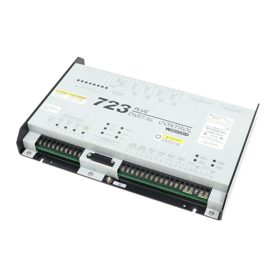
723PLUS Digital Marine Control Manual 26482 Figure 1-1. 723PLUS Digital Speed Control Woodward... -
Page 15: Figure 1-2. 723Plus Marine Torque Sharing System
Manual 26482 723PLUS Digital Marine Control Figure 1-2. 723PLUS Marine Torque Sharing System Woodward... - Page 16 723PLUS Digital Marine Control Manual 26482 Woodward...
-
Page 17: Figure 1-3. Functional Block Diagram
Manual 26482 723PLUS Digital Marine Control Figure 1-3. Functional Block Diagram Woodward... - Page 18 723PLUS Digital Marine Control Manual 26482 Woodward...
-
Page 19: Figure 1-4. Control Wiring Diagram
Manual 26482 723PLUS Digital Marine Control Figure 1-4. Control Wiring Diagram Woodward... -
Page 20: Figure 1-5. System Wiring Overview
723PLUS Digital Marine Control Manual 26482 Figure 1-5. System Wiring Overview Woodward... -
Page 21: Figure 1-6. Hand Held Programmer
Manual 26482 723PLUS Digital Marine Control Figure 1-6. Hand Held Programmer Woodward... -
Page 22: Chapter 2. Installation
If any damage is found, immediately notify the shipper. Power Requirements The low voltage version of the 723PLUS Digital Marine Control requires a voltage source of 18 to 40 Vdc. To prevent damage to the control, do not exceed the input voltage range. -
Page 23: Specific Marine Installation Requirements
Notch requirements, instead of a secondary metal shield for cabling, consult the ship builder. Acceptability of the installation for obtaining 6 dB of RF attenuation in the 156–165 MHz range must be provided by the ship builder. Woodward will not know the ship installation application or requirements to provide guidance. -
Page 24: Figure 2-1. 723Plus Control Internal Jumpers
723PLUS Digital Marine Control Manual 26482 Figure 2-1. 723PLUS Control Internal Jumpers Woodward... -
Page 25: Electrical Connections
&—tandem outputs are designed to supply a maximum of 160 mA into two actuators connected in series. Electrical Connections External wiring connections for a typical 723PLUS control installation are shown in Figure 1-5. The control wiring connections (Figure 1-4) are explained in the rest of this chapter. - Page 26 Power supply output must be low impedance (for example, directly from batteries). DO NOT power the control from high-voltage sources with resistors and zener diodes in series with the control power input. The 723PLUS control contains a switching power supply which requires a current surge (7 A) to start properly.
- Page 27 Manual 26482 723PLUS Digital Marine Control The relay contact on terminals 5/6 for Relay Output #2 is used when internal major alarm conditions are to be used by other devices in the application. No connection is required if the major alarm function is not used in the application.
- Page 28 Torque sharing is performed entirely with LON communication and negates the need for any separate torque sharing wiring connections. LON #1 terminals 23 and 24 connect to LON #1 on a mating 723PLUS Digital Marine control to provide the data and signals needed for correct clutch control and mechanical torque sharing in a two-engine marine propulsion system.
- Page 29 Chapter 4 for instructions on setting the node address. For optimum EMC performance, the network cable shield should be landed on one end only at either 723PLUS chassis, and the exposed wire length limited to 25 mm (1 inch). Acceptable cable is available from Woodward, Belden, or other suppliers...
- Page 30 723PLUS Digital Marine Control Manual 26482 Run/Stop (Input A; Terminal 29) The external contact used to activate the Run/Stop command connects to terminal 29 (Discrete Input A). This discrete input changes the control operation by immediately decreasing the fuel demand to zero. The Run/Stop command is the preferred means of signifying a normal engine shutdown.
- Page 31 This contact input is an indication from the actuator that it is running on the mechanical ballhead governor. This optional input is used for fault detection (723PLUS not in control) and can only be used with appropriate reverse-acting actuators. Alarm Reset (Input H; Terminal 36) The input switch or relay contact used to activate the Alarm Reset command connects to terminal 36 (Discrete Input H).
- Page 32 The fuel rack position input is a signal from a transducer, usually an LVDT or RVDT, that allows the 723PLUS control to accurately measure the amount of fuel given to the engine. The 1–5 Vdc input signal is scaled for 0–100% fuel rack position.
- Page 33 19200, then port J3 cannot be 38400, and if J2 is set for a baud rate of 38400, then port J3 cannot be 19200. The default baud rate is 19200. In this application, Port J2 of the Starboard 723PLUS and the Port 723PLUS are connected together and must use the multi-drop feature of Servlink when connecting to the network.
-
Page 34: Installation Checkout Procedure
723PLUS Digital Marine Control Manual 26482 FAILED SPD SENSOR #1 and #2 LEDs The FAILED SPD SENSOR #1 and #2 LEDs are red. The FAILED SPD SENSOR LEDs are programmed to illuminate if a speed sensor fault has been detected. FAILED SPD SENSOR #1 illuminates LED #1 when a speed sensor 1 fault has been detected, and FAILED SPD SENSOR #2 illuminates LED #2 when a speed sensor 2 fault has been detected. -
Page 35: Chapter 3. Description Of Operation
Actuator Output Speed Control The primary job of this 723PLUS control is to control the engine speed. The control compares the engine speed to the speed reference and then adjusts the actuator output to maintain a zero error between engine speed and the speed reference. -
Page 36: Figure 3-1. Speed Sensor Roll-Off Filter
The speed sensors also have a failsafe voltage level. The 723PLUS control must have at least 1 Vrms MPU voltage to operate. An amplitude less than 1 Vrms is considered to be a failed speed signal, and the 723PLUS control will go to minimum fuel. - Page 37 4 to 20 mA or 1 to 5 Vdc Remote Speed Setting input. The 723PLUS for the first engine clutched in is the master, which responds to the speed reference inputs and uses all internal speed reference ramp rates. The...
- Page 38 723PLUS Digital Marine Control Manual 26482 When the maneuvering mode input is closed, the engine speed reference will ramp from its current value to the maneuvering speed setpoint at the 05 RAISE SPEED RATE. This is true even if the engine speed is actually higher than the maneuvering speed setpoint when the maneuvering speed input is closed.
-
Page 39: Figure 3-2. Speed Reference
Manual 26482 723PLUS Digital Marine Control Figure 3-2. Speed Reference Dynamic Adjustments Dynamic adjustments are the settings that affect the stability and transient response of the engine. The objective of dynamic adjustments is to obtain an optimum, stable engine speed response from minimum speed/load to rated speed/ load operation. - Page 40 Fuel Limiting Function The second primary function of this 723PLUS control is to provide fuel rack limiting to protect the engine. All the fuel limiters and the PID output are applied to the actuator LSS (low signal select) bus. The lowest LSS input is “in Control”...
- Page 41 Manual 26482 723PLUS Digital Marine Control Load Sharing (Torque or Actuator Fuel Demand) 06 TORQUE INPUT % and 03 SCALED ACT COMMAND % is the percentage of rated engine load. Proper setting provides a 0% signal at minimum engine load (no-load) and a 100% signal at maximum engine load (rated load) based on either the torque sensor input or the actuator fuel demand output.
-
Page 42: Torque Sharing
If this is the second unit being clutched, the engine speeds are matched (synchronized), then the clutch is closed. The 723PLUS control then begins to soft load the second engine until its torque equals, within 5%, the internal torque sharing signal. At this point the internal torque sharing switch closes and the two 723PLUS controls begin operating in the torque sharing mode. -
Page 43: Chapter 4. Service And Configure Menus
Watch Window and Servlink Software Watch Window was developed by Woodward to be a Servlink client software product to provide a generic PC interface for any 723PLUS control, and is a very powerful setup, testing, and troubleshooting tool. Watch Window provides a means... -
Page 44: Menus
Manual 26482 Menus The 723PLUS has two sets of menus; the Service menus and Configure menus. The Service menus allow easy access and tuning while the engine is running. The Configure menus may only be entered if the I/O is shut down, and hence the engine stopped. - Page 45 + (plus) Decreases set point values by one step at a time. (solid square) Not used. Displays the 723PLUS control part number and software revision level. To return to menu header or to main screen. SAVE Saves entered values (set points).
-
Page 46: Figure 4-1. Hand Held Programmer Functions
When the hand held programmer is not being used for extended periods, it is recommended that it be disconnected from the 723PLUS control. The hand held programmer may provide an easier path for radio and other EMI signals to enter the 723PLUS control and cause undesirable conditions. -
Page 47: Servlink / Watch Window Pc Interface
Servlink / Watch Window PC Interface The connection of a computer is only required for calibration and setup of the 723PLUS control on a prime mover. The computer and Watch Window software is not required, and not necessary, for normal operation of the prime mover, unless Modbus is being used for monitoring. - Page 48 Servlink Server. The 723PLUS’s default baud rate is 19200, which needs to be entered in the Servlink Network Options window. Servlink will be initialized correctly for all other port parameters except BAUD rate.
- Page 49 Manual 26482 723PLUS Digital Marine Control Step 2: Click on File \ New to open a Network Options menu. Select the correct Port for your computer (Com 1 is default). Select Point-to-Point for the Mode, and select 19200 for the Baud Rate.
- Page 50 723PLUS Digital Marine Control Manual 26482 Step 4: If the red scanner bars cannot locate a control, then check to make sure that there is power on the control, and that a null modem (cross-over) cable is connected to the control.
- Page 51 Step 6: Minimize the Servlink program (don’t close it down). Open Watch Window software. Go to Start \ Programs \ Woodward \ Watch Window Standard \ Watch Window Standard, and click on the Watch Window Standard to start the software.
- Page 52 Save Application Settings icon. All the tunable values presently set in the control will be saved to a file and can be loaded into this 723PLUS, control to reprogram it to the saved values or into another 723PLUS, at a later time.
- Page 53 Manual 26482 723PLUS Digital Marine Control Follow these steps to save and reload the variables from the control: Step 1: Servlink and Watch Windows must be open to upload or save the variables to your computer. Click on the “Save Application Settings” icon Step 2: The software will ask you where to save the application settings file.
- Page 54 The software will ask you where to save the application settings file. The file extension is .cfg. This process can be executed even while the engine is running. It will not interrupt the 723PLUS. A progress bar will show you when the upload is finished. It should only take about 10-20 seconds.
-
Page 55: Configure Menus
When accessing the configuration menus the 723PLUS control will activate an I/O lock on the hardware. All outputs will be turned off (zero current/volts, extinguished LEDs) or de-energized (open contacts). - Page 56 01 LON ADDRESS CH#1 is the node address for LON Channel #1 and must be set at 1 or 2. The node address must be the same for both LON Channels #1 and #2 within the same 723PLUS control. The mating 723PLUS control must be assigned the remaining node address choice.
- Page 57 Enabling any one or a combination of the following alarms is acceptable as they are linked together as logical “ORs”. This is relay output #2, 723PLUS control terminals #5 and #6. This is a normally energized contact and will provide a shutdown signal when de-energized.
- Page 58 Enabling any one or a combination of the following alarms is acceptable as they are linked together as logical “ORs”. This is relay output #1, 723PLUS control terminals #3 and #4. The output goes to the TANO panel and will alarm a Minor Governor Alarm when energized.
- Page 59 Manual 26482 723PLUS Digital Marine Control 08 CLON CH2 ERROR (*T/F)—Set this value “FALSE” if no minor alarm output is desired when a Control LON Channel 2 error is detected. Set this value “TRUE” if a minor alarm output is desired when a Control LON Channel 2 error is detected.
-
Page 60: Service Menus
ACTUATOR MODE SWITCH DELAY discrete input into a minor or major alarm state. F**CFIG COM PORT 2** The 723PLUS has two serial ports. Port 2 and Port 3 are configured as Servlink ports. 01 PORT 2 ADDRESS determines the port’s multidrop Servlink network address. - Page 61 01 ACT SHUTDOWN (T/F)—A “TRUE” displayed indicates that the 723PLUS is asking the actuator driver output to go to the minimum fuel point. A “FALSE” displayed indicates that the 723PLUS is not asking the actuator driver output to go to the minimum fuel point.
- Page 62 723PLUS Digital Marine Control Manual 26482 07 CH1 LON ERROR (*T/F)—A “TRUE” displayed indicates that a communications error has occurred on Control LON Channel 1. 08 CH2 LON ERROR (*T/F)—A “TRUE” displayed indicates that a communications error has occurred on Control LON Channel 2.
- Page 63 Level alarm has not been detected. 13 HIGH SPEED SW (T/F)—A “TRUE” displayed indicates that the engine speed has exceeded the 723PLUS Engine Overspeed Trip point. A “FALSE” displayed indicates that the engine speed has not exceeded the 723PLUS Engine Overspeed Trip point.
- Page 64 Level alarm has not been detected. 12 HIGH SPEED SW (T/F)—A “TRUE” displayed indicates that the engine speed has exceeded the 723PLUS Engine Overspeed Trip point. A “FALSE” displayed indicates that the engine speed has not exceeded the 723PLUS Engine Overspeed Trip point.
- Page 65 Manual 26482 723PLUS Digital Marine Control 15 ACT CUR DEV EXCEEDED (T/F)—A “TRUE” displayed indicates that the actuator current deviation between the engines has exceeded the maximum deviation for the specified time limit. 16 RESET ALL ALARMS (T/F)—Toggle this value from “FALSE” to “TRUE” to reset any of the alarms once they have been cleared.
-
Page 66: Figure 4-3. Speed Filter
723PLUS Digital Marine Control Manual 26482 Figure 4-3. Speed Filter 11 MANEUVER GAIN (*0.1–500.0)—The maneuver gain is set to provide stable control of the engine at maneuver speed conditions. F**DYNAMICS CLUTCHED** These settings are used only when this engine's clutch is closed. - Page 67 Manual 26482 723PLUS Digital Marine Control 10 INITIATE BUMP—Tests the dynamics settings by temporarily applying a decreased fuel demand transient to stimulate a control response. Both the magnitude (ACT BUMP LEVEL) and duration (ACT BUMP DURATION) of the transient may be set under service menu *RESPONSE TESTING*. To initiate an actuator bump, toggle INITIATE BUMP to TRUE then back to FALSE while the engine is operating in a normal steady state loaded or unloaded condition.
-
Page 68: Figure 4-4. Gain Slope
723PLUS Digital Marine Control Manual 26482 Figure 4-4. Gain Slope Figure 4-5. Gain Window Woodward... -
Page 69: Figure 4-6. Typical Transient Response Curves
Manual 26482 723PLUS Digital Marine Control Figure 4-6. Typical Transient Response Curves Woodward... - Page 70 07 RESET INPUT CONTACT (T/F)—Shows the status of the Reset contact (terminal 36). 08 SERVLINK SELECTED (T/F)—Shows the status of the Servlink selector switch contact or jumper (terminals 9 and 10). K**RESPONSE TESTING** Response Testing is used for initial dynamic setup of the 723PLUS governor. Woodward...
- Page 71 Manual 26482 723PLUS Digital Marine Control 01 ACT BUMP ENABLE—Set TRUE to enable the actuator bump function for 60 minutes. Set to FALSE to disable this function and to reset the actuator bump 60- minute timer. 02 ACT BUMP DURATION (0.1–2.0 sec)—This is the time (in seconds) that the actuator bump will last once initiated.
- Page 72 723PLUS Digital Marine Control Manual 26482 07 TORQUE INPUT % displays the torque input of 4–20 mA converted to a percentage. When finished calibrating the 03 SCALED ACT COMMAND % and the 07 TORQUE INPUT % settings, this value and the TORQUE INPUT % will read approximately the same values from no load to full load.
- Page 73 Manual 26482 723PLUS Digital Marine Control 12 TORQUE INPUT (4-20 mA)—This value reads the input value (4–20 mA) of the torque sensor on terminals 42 and 43. 13 TORQUE OUT FT/LB OFFSET (*–200, 200)—This value adjusts the torque readout which converts the incoming torque value of 4.0 mA to an actual torque value in foot-pounds.
- Page 74 723PLUS Digital Marine Control Manual 26482 07 LOAD SHARE GAIN (*0.1–10.0)—This is the gain, expressed as a ratio of rated speed, that is used to scale the torque sharing error bias signal. This bias signal is applied to the speed reference to accomplish equal torque sharing.
-
Page 75: Chapter 5. I/O Verification And Calibration
1–5 Vdc input. Then 1 Vdc can be used in place of 4 mA, and 5 Vdc can be used in place of 20 mA. If the 723PLUS control response or the Watch Window or hand held readout do not agree with the information listed, stop and correct the problem before continuing with the next step. - Page 76 723PLUS Digital Marine Control Manual 26482 Run/Stop Switch (Discrete Input A) Place the Run/Stop switch in the closed position. The prompt 01 RUN / STOP CONTACT, under the header J**DISCRETE IN**, should read “TRUE”. Place the Run/Stop switch in the open position. The 01 RUN / STOP CONTACT prompt should read “FALSE”.
- Page 77 Manual 26482 723PLUS Digital Marine Control Alarm Reset Switch (Discrete Input H) Place the Alarm Reset switch in the Reset position (closed). The prompt 07 RESET INPUT, under the header J**DISCRETE IN**, should read “TRUE”. Place the Alarm Reset switch in the Non-Reset position (open). The 07 RESET INPUT prompt should read “FALSE”.
- Page 78 723PLUS control was in run mode. LED #3 This LED will flash on and if when the 723PLUS control LON ADDRESS CH#1 and LON ADDRESS CH#2 are not set or are improperly set. Do not parallel engines until this LED has been extinguished.
- Page 79 Speed Sensor 2 is an optional input. Verify the MPU shield is tied only to the 723PLUS control ground and nowhere else in the system. If an MPU is used for the speed sensor, measure the resistance across terminals 13 & 14. The resistance depends on the MPU used, but should be less than 250 .
-
Page 80: I/O Calibration
LON #1 and LON #2 networks. The LON #1 and LON #2 line shields must be connected only at one of the 723PLUS controls. The Control LON torque sharing signals will be tested after the engine is running. - Page 81 Manual 26482 723PLUS Digital Marine Control With the Handheld programmer or the Watch Window PC interface, go through the service headers and preset any applicable menu items. Many of the service headers do not have any adjustable menu items available and can be skipped.
-
Page 82: Figure 5-1. Analog Output Calibration Example
723PLUS Digital Marine Control Manual 26482 Figure 5-1. Analog Output Calibration Example Speed Sensor #1 (Speed Sensor Input #1) No calibration required. Speed Sensor #2 (Speed Sensor Input #2) No calibration required. Analog Output #3 No calibration needed. Analog Output #4 Analog output #4 is configured for Rack Position and is set for the preferred output selection to provide a 4–20 mA output signal based on the 1–5 Vdc Rack... - Page 83 Verify with a voltmeter that the remote speed setting device outputs 1 Vdc at the idle or minimum position to the 723PLUS and 5 V to the 723PLUS at the rated or maximum position. With the Handheld programmer or...
-
Page 84: Engine Start-Up
Figure 5-2. Start Fuel Limit Engine Start-up The 723PLUS control pre-calibration is now complete and the engine is ready to be started. The first attempt to start the engine should be done with the fuel shut off to prevent the engine from starting. This will allow the 723PLUS control, actuator, and actuator wiring to be checked prior to actually running the engine. - Page 85 Manual 26482 723PLUS Digital Marine Control Select the idle speed position from the speed setting device. Attempt to start the engine. If the engine does not start or hesitates, increase the start fuel limit. Once the engine has started and is running, the dynamics can be adjusted for optimal performance.
- Page 86 723PLUS Digital Marine Control Manual 26482 01 Idle Gain is too low. If the preceding procedure does not improve the slow periodic cycling of the engine speed, the control may be limiting cycling through the low gain control region set by the Window Width set point.
-
Page 87: Figure 5-3. Gain Slope
Manual 26482 723PLUS Digital Marine Control If operation in this range is satisfactory, no further dynamic adjustments are necessary. If during changes in load or an actuator bump, excessive speed errors occur, increase the Gain Slope adjustment until engine performance is satisfactory. - Page 88 Cylinder Temperatures, and Manifold Air Pressures using external monitoring devices. Synchronizing, Clutching, and Loading Adjustments Prior to testing the clutching and declutching of the 723PLUS control, the I/O calibration, and engine start-up, and torque sharing calibration procedures must be completed.
- Page 89 When clutching two engines together, it is useful to have one Handheld programmer or the Watch Window PC interface for each 723PLUS control. When clutching two units together for the first time, monitor the calibrated fuel rack position, 03 ACTUATOR COMMAND % (A**DISPLAY 1**).
-
Page 90: Conclusion
TANO System to read the fuel rack position on the engine. There is a Heinzmann rotary converter that converts Rack Position to a 1–5 Vdc signal. This signal is sent to the 723PLUS, but is basically passed through to the TANO System. To calibrate this output, manually pull the governor fuel rack to minimum fuel and make sure the output in Service Menu: M**ANALOG IN/OUT CALIB**, under the 08 RACK OUT (4–20 mA) reads 4.0 mA. -
Page 91: Figure 5-4. Speed And Load-Sharing Control Loops
Manual 26482 723PLUS Digital Marine Control Figure 5-4. Speed and Load-Sharing Control Loops Woodward... - Page 92 Torque Transducer. This signal is used for sharing the actual torque across both engines while the engines are clutched together. If the torque signal fails, then the 723PLUS uses the actuator fuel demand as a way of determining load on the engine. Therefore it is critical that this input be calibrated accurately.
-
Page 93: Chapter 6. Faults And Troubleshooting
See the description of operation in Chapter 3 for the different selections. Both Speed Sensors Failed Both speed sensors faulted at the same time will cause the 723PLUS to go to the minimum fuel position. The speed sensor faults are latching faults (latching means the fault/alarm condition remains in effect even if the problem disappears, until the control is reset—see Alarm/Fault Resets below). -
Page 94: Alarm Delay Time
When the engine is in stop mode, the speed sensor fault is overridden. When the 723PLUS control is powered up or re- booted by exiting Configuration, the speed sensor faults may be active. As soon as the engine attempts to start, the speed sensor faults should clear. -
Page 95: Overspeed Trip
Channel #2 have a communication fault. The four causes are: 1.) The configured node addresses of both 723PLUS controls for LON Channel #1 and LON Channel #2 are the same. 2.) LON #1 and LON #2 of one control has a hardware fault (replace control). -
Page 96: Pid At Low Level Fault
The torque signals from both engines are measured in both 723PLUS controls. If the torque signals are different by a certain percentage and for a certain period of time, both units will switch to using the back up Actuator Fuel Demand load sharing. - Page 97 Power supply may be dropping out, especially if start fuel position). the cranking batteries are being used to power the 723PLUS control. The power supply polarity may be reversed (dc units only). Replace the hardware as necessary.
- Page 98 1b. Actuator drive rotation incorrect. 1c. Verify the actuator and 723PLUS control are the same action (forward or reverse). Verify that as the 723PLUS control actuator command goes to maximum fuel, the fuel rack is moved in the increase fuel direction. Actuator terminal shaft position should be proportional to the actuator command.
- Page 99 See the remote speed setting calibration for troubleshooting. The 723PLUS control will not track the remote above or below the rated and idle speed settings. 3. Slow speed reference 3.
- Page 100 5. Mechanical governor 5a. Often referred to as ballhead interference. The mechanical interference/problem. ballhead governor and 723PLUS control speed settings are too close to each other. The speed control governors (electrical and mechanical) are attempting to control the engine speed at the same time.
- Page 101 Route suspect wiring outside of conduit and verify engine instability goes away. 8d. If 723PLUS control wiring is isolated down to power supply, MPU, and actuator, check condition of solder joints at MPU and actuator connectors. Check all terminal connections for tightness.
- Page 102 Symptom Cause Test/Remedy Engines do not share 1. Improper torque sensor 1. The 723PLUS control can only share load as well as the torque equally. transducer or default torque sensor transducers, actuator linkages, and engine percent actuator torque or pump(s) are calibrated. With the hand held calibration.
-
Page 103: Chapter 7. Product Support And Service Options
A current list of Woodward Business Partners is available at www.woodward.com/directory. Product Service Options Depending on the type of product, the following options for servicing Woodward products may be available through your local Full-Service Distributor or the OEM or Packager of the equipment system. -
Page 104: Returning Equipment For Repair
To prevent damage to electronic components caused by improper handling, read and observe the precautions in Woodward manual 82715, Guide for Handling and Protection of Electronic Controls, Printed Circuit Boards, and Modules. -
Page 105: Engineering Services
Field Service engineering on-site support is available, depending on the product and location, from one of our Full-Service Distributors. The field engineers are experienced both on Woodward products as well as on much of the non- Woodward equipment with which our products interface. -
Page 106: Technical Assistance
Manual 26482 Technical Assistance If you need to contact technical assistance, you will need to provide the following information. Please write it down here before contacting the Engine OEM, the Packager, a Woodward Business Partner, or the Woodward factory: General... -
Page 107: Appendix A. Serial Communication Port Wiring
Figure A-1. 723PLUS RS-232 Connections The RS-422 connections are shown in Figure A-2. The maximum distance from the Master Modbus Device to the 723PLUS control is 1219 m (4000 ft). Figure A-2. 723PLUS RS-422 Connections with Optional Termination at Receiver... -
Page 108: Figure A-3. 723Plus Rs-485 Connections With Optional Termination
Manual 26482 The RS-485 connections are shown in Figure A-3. The maximum distance from the Master Modbus Device to the 723PLUS control is 1219 m (4000 ft). Figure A-3. 723PLUS RS-485 Connections with Optional Termination RS-422 and RS-485 can use a multi-drop set-up where more than one device is connected to a master device. -
Page 109: Grounding And Shielding
Manual 26482 723PLUS Digital Marine Control Grounding and Shielding The RS-422 specifications state that a ground wire is needed if there is no other ground path between units. The preferred method to do this is to include a separate wire in the cable that connects the circuit grounds together. Connect the shield to earth ground at one point only. -
Page 110: Appendix B. Programming Checklist
723PLUS Digital Marine Control Manual 26482 Appendix B. Programming Checklist We recommend you write down the final value of each menu item here so you will have a record if you later need to reprogram or replace the control. From the Handheld Main Menu Header press ‘ID’, or from Watch Window or the STD PC interface, select “Control Properties”... - Page 111 Manual 26482 723PLUS Digital Marine Control D**CONFIG MINOR ALARMS** Default 01 MPU 1 FAILED #FALSE 02 MPU 2 FAILED #FALSE 03 BOTH MPU FAILED #TRUE 04 REMOTE SPEED FAILED #TRUE 05 TORQUE INPUT FAILED #FALSE 06 RACK POSN INPUT FAILED...
- Page 112 723PLUS Digital Marine Control Manual 26482 C**MAJOR ALARMS** Default Field Settings 01 MAJOR ALARM Display Only 02 MPU 1 FAILED Display Only 03 MPU 2 FAILED Display Only 04 MPU1 AND MPU2 FAILED Display Only 05 REMOTE SPEED FAILED Display Only...
- Page 113 Manual 26482 723PLUS Digital Marine Control G**SPEED REFERENCE** Default (Low, High) 01 RAISE SPEED LIMIT *1225 (100, 2200) 02 LOWER SPEED LIMIT *350 (100, 2200) 03 IDLE SPEED (RPM) *350 (100, 2200) 04 DECEL RAMP (SEC) *10.0 (0.0001, 500.0) 05 RAISE SPEED RATE (%/sec) *25.0 (1.0, 10000.0)
- Page 114 723PLUS Digital Marine Control Manual 26482 P**LOAD CONTROL** Default (Low, High) 01 CLUTCH SYNC TIME *2.0 (1.0, 120.0) 02 UNLOAD RATE *20.0 (0.01, 100.0) 03 LOAD RATE *20.0 (0.01, 100.0) 04 UNLOAD TRIP POINT *20.0 (0.0, 100.0) 05 CLUTCH IN TIME *5.0 (1.0, 120.0)
- Page 115 Manual 26482 723PLUS Digital Marine Control *DISPLAY 2* ACT SHUTDOWN Display Only ON DYNAMICS 2 Display Only SPEED CONTROL MODE Display Only ON MAX FUEL LIMIT Display Only ON START FUEL LIMIT Display Only ENGINE OVER SPED? Display Only CH1 LON ERROR...
-
Page 116: Appendix C. Menu Summary
723PLUS Digital Marine Control Manual 26482 Appendix C. Menu Summary Configure Menus E**ALARM/SD CONFIGURE** A**CONFIG SPD CONTROL** C**CONFIG MAJOR ALARMS 01 GEAR #1 TEETH 01 MPU 1 FAILED 01 ALARM DELAY TIME 02 GEAR #2 TEETH 02 MPU 2 FAILED... -
Page 117: Service Menus
Manual 26482 723PLUS Digital Marine Control Service Menus A**DISPLAY 1** E**DYNAMICS DE-CLUTCHED** L**ACT / TORQUE CALIB* 01 ENGINE SPEED (RPM) 01 IDLE GAIN 1 01 ACT OUT % @ NO LOAD 02 SPEED REFERENCE (RPM) 02 RATED GAIN 1 02 ACT OUT % @ MAX LOAD... -
Page 118: 723Plus Control Specifications
723PLUS Control Specifications Input Power Low Voltage Model 18–40 Vdc (24 or 32 Vdc nominal) Power Consumption 40 W nominal Inrush Current 7 A for 0.1 ms Inputs Speed Signal Inputs (2) Speed Input Voltage 1.0–50.0 Vrms Speed Input Frequency Magnetic Pickup: 400 Hz to 15 kHz;... -
Page 119: Declarations
Declarations... - Page 120 Email and Website—www.woodward.com Woodward has company-owned plants, subsidiaries, and branches, as well as authorized distributors and other authorized service and sales facilities throughout the world. Complete address / phone / fax / email information for all locations is available on our website.
Need help?
Do you have a question about the 723PLUS and is the answer not in the manual?
Questions and answers