
Related Manuals for Woodward 3161 Governor


Summary of Contents for Woodward 3161 Governor
- Page 1 Product Manual 03101 (Revision C) Original Instructions 3161 Governor Installation and Operation Manual This document, and more, is available for download from Martin's Marine Engineering Page - www.dieselduck.net...
- Page 2 Revisions—Text changes are indicated by a black line alongside the text. Woodward reserves the right to update any portion of this publication at any time. Information provided by Woodward is believed to be correct and reliable. However, no responsibility is assumed by Woodward unless otherwise expressly undertaken.
-
Page 3: Table Of Contents
Installation Requirements ..................3 3. P ............. 6 HAPTER RINCIPLES OF PERATION Component Description ..................6 Operation of the 3161 Governor ................8 4. T ............... 11 HAPTER ROUBLESHOOTING 5. G ............... 13 HAPTER OVERNOR EPAIR ... - Page 4 Figure 1-1. 3161 Governor Outline Drawing ............2 Figure 3-1. Schematic of the 3161 Governor ............10 Figure 5-1. Common Tools Used on the 3161 Governor ........14 Figure 5-2. Special Tools Used on the 3161 Governor ........14 ...
-
Page 5: Chapter 1. General Information
Chapter 1. General Information Description The 3161 governor is a mechanical-hydraulic device that senses speed and is mechanically linked to and controls the energy source of dual fuel engines, diesel engines, or steam turbines. The maximum work output is 6 ft-lb (8 J) over the full 42 degrees travel of its output (terminal) shaft. -
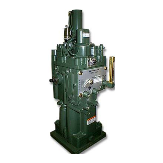
Page 6: Figure 1-1. 3161 Governor Outline Drawing
3161 Governor Manual 03101 Figure 1-1. 3161 Governor Outline Drawing Woodward This document, and more, is available for download from Martin's Marine Engineering Page - www.dieselduck.net... -
Page 7: Chapter 2. Installation Procedures
Attach the prime mover linkage to the output shaft of the governor. The maximum work output of the 3161 governor is 6.0 ft-lb (8.1 J) over the full 42 degrees travel of its output shaft. The recommended travel of the output shaft is 28 degrees between the no load and full load positions. - Page 8 3161 Governor Manual 03101 Speed Setting Shaft Linkage Attach the speed setting linkage to the governor speed setting shaft. Typically, there will be a 50 rpm speed change for each degree of speed setting shaft rotation, however this may vary depending on the speed setting spring used in the governor.
- Page 9 Manual 03101 3161 Governor Table 2-1. Oil Viscosity Chart Needle Valve Adjustment After the prime mover has started and the governor is controlling, open the needle valve (turn it CCW) until governor operation just becomes unstable. Then slowly close the needle valve (turn it CW) until the governor just becomes stable.
-
Page 10: Chapter 3. Principles Of Operation
3161 Governor Manual 03101 Chapter 3. Principles of Operation Component Description Gerotor Oil Pump—The gerotor oil pump is located in the base of the governor. The inner rotor of the pump is driven by a pin in the drive shaft, and carries the outer rotor around in mesh, pumping oil to the accumulator piston. - Page 11 Speed Droop The 3161 governor is an isochronous governor with the ability to operate in the droop mode by the adjustment of the internal droop pivot pin. The governor may be used in the droop mode to allow for load division between two or more prime movers connected to a single shaft or for operating in parallel.
-
Page 12: Operation Of The 3161 Governor
The schematic arrangement of the 3161 governor is shown in Figure 3-1, with the governor pilot valve calling for increased fuel. The 3161 governor has a self- contained oil supply (approximately 2.3 US qt/2.2 L). The oil passes from the suction side to the pressure side of the gerotor pump as the drive shaft is rotated by the prime mover. - Page 13 Manual 03101 3161 Governor Shutdown The limit/shutdown pilot valve is located in the supply line to the ballhead pilot valve plunger. When shutdown is initiated, the shutdown strap pushes the limit/shutdown plunger below the supply passage and drains oil from the supply to the ballhead pilot valve plunger.
-
Page 14: Figure 3-1. Schematic Of The 3161 Governor
3161 Governor Manual 03101 Figure 3-1. Schematic of the 3161 Governor Woodward This document, and more, is available for download from Martin's Marine Engineering Page - www.dieselduck.net... -
Page 15: Chapter 4. Troubleshooting
Manual 03101 3161 Governor Chapter 4. Troubleshooting Governor faults are usually revealed as speed variations of the prime mover, however, it does not necessarily follow that all speed variations indicate governor faults. Troubleshoot the governor to localize a problem before attempting disassembly and repair. - Page 16 3161 Governor Manual 03101 Problem Question Procedure YES— Is the linkage adjusted properly? Is load excessive? Is the voltage regulator (if used) set properly? Is the fuel stop on the prime mover set correctly? Prime mover will Is the governor at full NO—...
-
Page 17: Chapter 5. Governor Repair
Governor Repair Introduction Chapter 5 provides instruction for the disassembly, inspection, cleaning and repair of the 3161 governor. Wear approved eye protection during disassembly, cleaning, and assembly of parts, to prevent possible eye injury. This governor Is a precision device and should be treated as such. -
Page 18: Figure 5-1. Common Tools Used On The 3161 Governor
3161 Governor Manual 03101 Figure 5-1. Common Tools Used on the 3161 Governor Figure 5-2. Special Tools Used on the 3161 Governor Woodward This document, and more, is available for download from Martin's Marine Engineering Page - www.dieselduck.net... - Page 19 See Figures 5-1 and 5-2 for tools to facilitate the disassembly and assembly of the governor. Not all of these tools may be needed, depending on the degree of disassembly. Tools can be ordered from Woodward (Fort Collins, Colorado, USA). Include in the order: ...
-
Page 20: Figure 5-3. Speeder Plug Removal
3161 Governor Manual 03101 Remove three screws (1) and lift out speeder plug bracket (37), shutdown/limit rod (40), limit floating lever (41), and limit rod (42). Carefully push down on speeder plug (123) and turn it until the floating lever (125) is clear of the terminal lever. -
Page 21: Figure 5-6. Removing Ballhead Cover
Manual 03101 3161 Governor Remove the ballhead assembly from the governor. Drive coupling (108) may come out with the ballhead assembly. If not, it will drop out when the governor is turned over (Figure 5-5). Figure 5-5. Ballhead Use an 1/8 inch Allen wrench to hold the pilot valve plunger while removing nut (119). -
Page 22: Figure 5-7. Ballhead Disassembly
3161 Governor Manual 03101 10. Gently tap on the end of flyweight pins (106) to remove from ballhead (109). Use ID snap ring pliers 189791 to remove snap ring (114). Carefully remove pilot valve plunger (112), and compensation bushing (113) from ballhead (109) (Figure 5-7). -
Page 23: Figure 5-9. Accumulator Loading Tool
Manual 03101 3161 Governor Figure 5-9. Accumulator Loading Tool 12. Turn the governor upside down. Remove four screws (75) from pump housing (82). 13. Remove pump housing (82) from base (95). Use two screwdrivers to gently lift the pump housing until it is free from the base. -
Page 24: Parts Inspection And Replacement
3161 Governor Manual 03101 Figure 5-10. Servo and Link Disassembly 19. Remove two screws (1), cover plate (35) and stop screws (34). 20. Remove needle valve (127) and air bleed plug (129). Do not remove oilite bearings unless replacement is necessary. -
Page 25: Figure 5-5. Ballhead
Manual 03101 3161 Governor Pistons, output shafts, speed setting shaft and the drive shaft may be lightly polished with a fine grit cloth or paper to restore a smooth finish to the bearing surface. Inspect all springs for rust and corrosion. -
Page 26: Governor Assembly
3161 Governor Manual 03101 Ballarms (110) Replace the ballarms if the toes have a worn flat that exceeds .030 inch in width. Ballarm Bearings (111) Replace rough or seized bearings. Replace bearing if measurable wear marks were found on pins (106). -
Page 27: Figure 5-11. Limit Shutdown Assembly
Manual 03101 3161 Governor Figure 5-11. Limit Shutdown Assembly Press drive shaft seal (84) to bottom of pump housing (82) (Figure 5-12). Figure 5-12. Drive Shaft Seal Assembly Install bowed retaining ring (89) on drive shaft (86). Press bearing (88) on the shaft. -
Page 28: Figure 5-13. Drive Shaft Retaining Rings
3161 Governor Manual 03101 Figure 5-13. Drive Shaft Retaining Rings 12. Install the drive shaft and pump assembly in base (95). Match the arrow on pump housing (82) with the arrow on base (95) for the correct drive rotation for your governor. - Page 29 Manual 03101 3161 Governor Be sure the thrust bearing and lower bearing race are over the top land of the pilot valve before the nut is tightened. The upper bearing race will seat on the top land. Torque nut (119) to 35–40 lb-in (4.0–4.5 Nm).
-
Page 30: Figure 5-14. Speeder Plug Bracket Assembly
3161 Governor Manual 03101 Figure 5-14. Speeder Plug Bracket Assembly 11. Install speed setting lever (36), speed setting shaft (28) and clamp screw (1). Use insert tool 8995-067 to install new speed setting shaft bearing. Shaft (28) must rotate freely. -
Page 31: Chapter 6. Governor Calibration
3161 Governor Chapter 6. Governor Calibration Introduction The 3161 governor must be calibrated to engine specifications. When requesting the correct specifications for your governor, contact Woodward (information on www.woodward.com). When requesting information for your governor, include the following information: ... - Page 32 3161 Governor Manual 03101 Rapidly change the position of the output shaft 5 to 15 degrees. The controlling rpm should change several rpm, then return slowly towards the original controlling rpm at 20 degrees output shaft position. Turn the needle valve counter-clockwise one turn. The speed should return to the original controlling rpm ±3 within 10 seconds.
-
Page 33: Chapter 7. Auxiliary Devices
Auxiliary Devices Introduction This chapter describes Auxiliary Devices that are available for the 3161 governor. These devices are installed and calibrated at the factory before shipment to the user. The shutdown devices may be added to a governor already in service without any further modification to the governor. -
Page 34: Figure 7-2. Pressure Shutdown
3161 Governor Manual 03101 Pressure Shutdown Figure 7-2 The pressure shutdown assembly is installed on top of the right front corner of the cover. Forty psi pressure (either air or hydraulic) is applied to the device to cause governor shutdown. The device will reset when the pressure drops below 20 psi (138 kPa). -
Page 35: Figure 7-3. Electric Shutdown
Manual 03101 3161 Governor Figure 7-3. Electric Shutdown Pneumatic Speed Setting Figure 7-4 The pneumatic speed setting device uses an external control pressure for setting governor speed. Control pressure is supplied to a speed setting bellows. High pressure oil is supplied to the speed setting device to position the speed setting piston and rod to set governor speed. -
Page 36: Figure 7-5. Speed Adjusting Motor And Manual Speed Adjustment
3161 Governor Manual 03101 Speed Adjusting Motor and Manual Speed Adjustment Figure 7-5 The 24 Vdc speed adjusting motor is installed on the governor cover, and rotates a speed adjusting screw to adjust the position of the governor speed adjusting lever. -
Page 37: Figure 7-6. Air Pressure Fuel Limiter
Manual 03101 3161 Governor Air Pressure Fuel Limiter Figure 7-6 The Air Pressure Fuel Limiter limits fuel in proportion to air pressure from the air manifold or air box, and is used to protect the turbocharger and limit smoke during acceleration. -
Page 38: Chapter 8. Replacement Parts
3161 Governor Manual 03101 Chapter 8. Replacement Parts Parts Information When ordering replacement parts, include the following information: Governor serial number and part number shown on the nameplate Manual number (this is manual 03101) Part reference number and part name from parts list... -
Page 39: Figure 8-1. Parts For 3161 Governor
Manual 03101 3161 Governor Figure 8-1. Parts for 3161 Governor Woodward This document, and more, is available for download from Martin's Marine Engineering Page - www.dieselduck.net... -
Page 40: Parts List For Figure 8-2
3161 Governor Manual 03101 Parts list for Figure 8-2 Ref. No. Part Name ......Quantity 03101-75 Screw ..........15 03101-76 Spring seat.......... 1 03101-77 Accumulator spring ......1 03101-78 Accumulator piston ......1 03101-79 Gerotor pump ........1 03101-80 O-ring 1.989 x 0.070 ......1 03101-81 Roll pin 0.125 x 0.438 ...... -
Page 41: Figure 8-2. Parts For 3161 Governor
Manual 03101 3161 Governor Figure 8-2. Parts for 3161 Governor Woodward This document, and more, is available for download from Martin's Marine Engineering Page - www.dieselduck.net... -
Page 42: Chapter 9. Product Support And Service Options
A current list of Woodward Business Partners is available at www.woodward.com/directory. Product Service Options Depending on the type of product, the following options for servicing Woodward products may be available through your local Full-Service Distributor or the OEM or Packager of the equipment system. -
Page 43: Returning Equipment For Repair
To prevent damage to electronic components caused by improper handling, read and observe the precautions in Woodward manual 82715, Guide for Handling and Protection of Electronic Controls, Printed Circuit Boards, and Modules. -
Page 44: Engineering Services
Field Service engineering on-site support is available, depending on the product and location, from one of our Full-Service Distributors. The field engineers are experienced both on Woodward products as well as on much of the non- Woodward equipment with which our products interface. -
Page 45: Technical Assistance
3161 Governor Technical Assistance If you need to contact technical assistance, you will need to provide the following information. Please write it down here before contacting the Engine OEM, the Packager, a Woodward Business Partner, or the Woodward factory: General... - Page 46 Email and Website—www.woodward.com Woodward has company-owned plants, subsidiaries, and branches, as well as authorized distributors and other authorized service and sales facilities throughout the world. Complete address / phone / fax / email information for all locations is available on our website.
Need help?
Do you have a question about the 3161 Governor and is the answer not in the manual?
Questions and answers