Woodward 505 Installation And Operation Manual
Digital control for steam turbines
Hide thumbs
Also See for 505:
- Manual for operation and installation (212 pages) ,
- Installation and operation manual (176 pages) ,
- Product manual (138 pages)
Table of Contents

Related Manuals for Woodward 505


Summary of Contents for Woodward 505
- Page 1 Product Manual 26839V1 (Revision B, 2/2017) Original Instructions 505 Digital Control for Steam Turbines 8200-1300, 8200-1301, 8200-1302 Manual 26839 consists of 2 volumes (26839V1 & 26839V2) Installation and Operation Manual Volume 1...
- Page 2 Revisions— A bold, black line alongside the text identifies changes in this publication since the last revision. Woodward reserves the right to update any portion of this publication at any time. Information provided by Woodward is believed to be correct and reliable. However, no responsibility is assumed by Woodward unless otherwise expressly undertaken.
-
Page 3: Table Of Contents
Manual 26839V1 505 Digital Control for Steam Turbines Contents ....................... 6 ARNINGS AND OTICES ..................8 LECTROSTATIC ISCHARGE WARENESS ......................9 EGULATORY OMPLIANCE 1. G .................... 14 HAPTER ENERAL NFORMATION Introduction ..............................14 Controller Overview ............................. 14 Functional Block Diagrams ......................... 17 ... - Page 4 Manual 26839V1 505 Digital Control for Steam Turbines Inlet Steam Pressure Compensation ......................85 Isolated PID Control ............................ 85 Emergency Shutdown ..........................86 Controlled Shutdown ........................... 87 Overspeed Test Function ..........................88 Local/Remote Function ..........................88 ...
- Page 5 Figure 1-2. Explanation of Symbols ......................17 Figure 1-3. Single or Split-Range Turbine Configurations ................18 Figure 1-4. 505 Keypad and Display ......................23 Figure 2-1. Functional Block Diagram (505D Control) ................25 Figure 2-2. 505D Outline Drawing ......................28 ...
- Page 6 Figure 5-21. HOME Menu showing “Startup Curve” IN-Focus ..............141 Figure 5-22. Overspeed Test Permissives ....................142 Figure 5-23. Internal (505) Overspeed Test ....................143 Figure 5-24. External Overspeed Test ...................... 143 Figure 5-25. ALARM Screen ........................145 ...
- Page 7 Manual 26839V1 505 Digital Control for Steam Turbines Table 6-7. Boolean Write Addresses ......................168 Table 6-8. Boolean Read Addresses ......................170 Table 6-9. Analog Reads .......................... 174 Table 6-10. Analog Write Addresses ......................180 Table 6-11. Control Status ........................180 ...
-
Page 8: Warnings And Notices
Manual 26839V1 505 Digital Control for Steam Turbines Warnings and Notices Important Definitions This is the safety alert symbol used to alert you to potential personal injury hazards. Obey all safety messages that follow this symbol to avoid possible injury or death. - Page 9 Manual 26839V1 505 Digital Control for Steam Turbines IOLOCK. When a CPU or I/O module fails, watchdog logic drives it into an IOLOCK condition where all output circuits and signals are driven to a known de-energized state as described below. The System MUST be designed such that IOLOCK and power OFF states will result in a SAFE condition of the controlled device.
-
Page 10: Electrostatic Discharge Awareness
Do not touch the components or conductors on a printed circuit board with your hands or with conductive devices. To prevent damage to electronic components caused by improper handling, read and observe the precautions in Woodward manual , Guide for Handling and Protection of Electronic Controls, 82715 Printed Circuit Boards, and Modules. -
Page 11: Regulatory Compliance
Manual 26839V1 505 Digital Control for Steam Turbines Regulatory Compliance European Compliance for CE Marking: These listings are limited only to those units bearing the CE Marking. Refer to DoC for applicability by part number. EMC Directive Declared to Directive 2014/30/EU of the European Parliament and of the Council of 26 February 2014 on the harmonization of the laws of the Member States relating to electromagnetic compatibility. - Page 12 Manual 26839V1 505 Digital Control for Steam Turbines This product is certified as a component for use in other equipment. The final combination is subject to acceptance by the authority having jurisdiction or local inspection. Marine Compliance: Lloyd’s Register of LR Type Approval Test Specification No.
- Page 13 Contact a Woodward Authorized Service Center if a replacement service is needed. The Low Voltage ATEX 505 Digital Control is suitable for use in Class I, Div 2, Gas Groups A,B,C and D & European Zone 2, Group IIC environments.
- Page 14 Manual 26839V1 505 Digital Control for Steam Turbines Substitution of components may impair suitability for Class I, Division 2 or Zone 2. Explosion Hazard The external ground lugs shown on the installation drawing must be properly connected to ensure equipotential bonding. This will reduce the risk of electrostatic discharge in an explosive atmosphere.
- Page 15 Manual 26839V1 505 Digital Control for Steam Turbines Safety Symbols Direct Current Alternating Current Both Alternating and Direct Current Caution, risk of electrical shock Caution, refer to accompanying documents Protective conductor terminal Frame or chassis terminal Woodward...
-
Page 16: Chapter 1. General Information
The 505 controller is designed to control single or dual (split range) actuator steam turbines (extraction steam turbines require the 505XT version). The 505 is field programmable which allows a single design to be used in many different control applications and reduces both cost and delivery time. It uses menu driven software to instruct site engineers on programming the control to a specific generator or mechanical drive application. -
Page 17: Figure 1-1. Typical Single Or Dual Inlet Steam Turbine
505 Digital Control for Steam Turbines The 505 control has five PID controllers that can affect the demand of the inlet steam flow into the turbine; the Speed/load PID controller, the Auxiliary PID controller, Auxiliary 2 PID controller, and the Cascade PID controller. - Page 18 Frequency dead-band. Using the 505 The 505 control has three normal operating modes, Configuration Mode, Service Mode and the Run Mode. See chapter 4 for more information about the User Levels required to enter each of these modes. Configuration Mode –...
-
Page 19: Functional Block Diagrams
505 Digital Control for Steam Turbines Functional Block Diagrams An overview of the 505 valve demands is shown in Figure 1-4. The Cascade and Auxiliary PIDs are optional controllers, and are shown in the following diagrams for PID relationship purposes only. Later in this manual, more detailed functional block diagrams will be shown in relative to each control loop PID. -
Page 20: 505 Inputs And Outputs
Manual 26839V1 505 Digital Control for Steam Turbines Figure 1-3. Single or Split-Range Turbine Configurations (Valve Demand Overview) 505 Inputs and Outputs Control Inputs Two redundant speed inputs are configurable to accept MPUs (magnetic pickup units), proximity probes or eddy current probes. - Page 21 Manual 26839V1 505 Digital Control for Steam Turbines HP Valve FDBK Position HP2 Valve FDBK Position Isolated PID PV Remote SP for Isolated PV Signal Monitoring #1 Signal Monitoring #2 Signal Monitoring #3 Start Temperature 1 Start Temperature 2 Twenty contact inputs are available. The first four are defaulted for the following functions: shutdown, reset, raise speed set point, and lower speed set point.
- Page 22 Manual 26839V1 505 Digital Control for Steam Turbines External Trip 6 External Trip 7 External Trip 8 External Trip 9 External Trip 10 External Alarm 1 External Alarm 2 External Alarm 3 External Alarm 4 External Alarm 5 External Alarm 6...
- Page 23 Manual 26839V1 505 Digital Control for Steam Turbines HP Valve Demand HP2 Valve Demand Inlet Pressure Input I/H Actuator 1 Feedback Readout I/H Actuator 2 Feedback Readout Isolated PID Dmd Output Isolated PID PV Input Signal Isolated PID Setpoint Remote Isolated PID Setpoint...
- Page 24 Manual 26839V1 505 Digital Control for Steam Turbines Auxiliary Control Enabled Auxiliary Control Active Auxiliary PID in Control Remote Auxiliary Setpoint Enabled Remote Auxiliary Setpoint Active Auxiliary 2 Control Enabled Auxiliary 2 Control Active Auxiliary 2 PID in Control Remote Auxiliary 2 Setpoint Enabled...
-
Page 25: Keypad And Display
The front panel display is designed to provide the user with multiple levels of access for configuring, calibrating, tuning, operating and monitoring the turbine operation. No additional control panels are required to operate the turbine, every turbine control function can be performed from the 505’s front panel. -
Page 26: Watchdog Timer/Cpu Fault Control
The IO Lock and CPU Health LED’s on the front left side of the display – are always in an identical state as the LED’s on the back side of the control. They are completely controlled by the 505 control hardware and are not controlled by the GAP application. -
Page 27: Chapter 2. Hardware Specifications
Hardware Specifications Flex505 Description and Features The Flex505 controller is a significant upgrade to the existing 505 product line with enhanced CPU, Graphical display, communications, and I/O functions. Note: This controller supports expanded I/O options when using Woodward CAN distributed I/O nodes (RTCnet and LINKnet HT). -
Page 28: Environmental Specifications
Marine specification applies to the ATEX/Marine qualified unit Maintenance Info and Recommendations The 505 Control is designed for continuous operation in a typical industrial environment and includes no components that require periodic service. However, to take advantage of related product software and hardware improvements, we recommend that your product be sent to a Woodward Authorized Service Facility after every five to ten years of continuous service for inspection and component upgrades. -
Page 29: Electromagnetic Compatibility (Emc)
505 Digital Control for Steam Turbines Display LCD with backlight The 505 uses a low power LED backlight display with a life expectancy of 60K hours to half brightness, at maximum operating temperature. If the display appears dim, use the “SCREEN SETTINGS” menu to verify the brightness setting and adjust as needed with the ADJ ARROW-BRIGHTNESS keypad combination. -
Page 30: Figure 2-2. 505D Outline Drawing
Manual 26839V1 505 Digital Control for Steam Turbines Figure 2-2. 505D Outline Drawing Woodward... -
Page 31: Input Power Specification
Manual 26839V1 505 Digital Control for Steam Turbines Input Power Specification Specifications (LV) LV Input Voltage range: 18-36 Vdc Input Power (max): < 77 W, 4.3 A max Output Voltage Holdup time: > 14 ms with 24 Vdc input voltage Isolation to other circuits: >... -
Page 32: Visual Indicators (Led's) & Cpu Configuration
Manual 26839V1 505 Digital Control for Steam Turbines Visual Indicators (LED’s) & CPU Configuration Visual indicators are located on the Front Panel keypad, the controller board, back cover, and related communications ports for diagnostic use. CPU OK indicator (green/red): This bi-color LED indicates the CPU status is operational (green) or faulty (red). -
Page 33: Communications (Can)
(4) Isolated CAN ports are available for general communications as well as simplex or redundant distributed control. Compatible devices include Woodward RTCnet nodes, LINKnet HT nodes, DVP valve products, and other 3rd party devices. Removable latching connector plugs are provided for field wiring. - Page 34 Max wire size: 1.3 mm² / 16 AWG for single wires, 0.5 mm² / 20 AWG for two wires Table 2-6. CAN Cable Specifications Belden YR58684 (Woodward PN 2008-1512) communications / CAN cable is approved and recommended. This is a smaller and more flexible 0.3 mm² / 22 AWG, low capacitance cable suitable for tight routing in industrial environments.
-
Page 35: Communications (Rs-232/Rs-485)
Flex500 / 505 hardware products. However, the shield must also be directly terminated to chassis (Earth) at one point in the network. In the case of Woodward equipment, the direct ground is meant to be located at the master device end, as it exits the master device’s enclosure. -
Page 36: Communications (Service Ports)
For debug use, a Woodward PN 5417-1344, USB to serial debug cable is required to attach this port to a PC. This port is to be used by trained Field Service personnel only! Dura-Clik connector (male) Pin 1 –... -
Page 37: Hardware - Terminal Blocks & Wiring
Manual 26839V1 505 Digital Control for Steam Turbines Hardware - Terminal Blocks & Wiring Figure 2-5. 505 Back Cover Label Woodward... -
Page 38: Terminal Block Connectors
Manual 26839V1 505 Digital Control for Steam Turbines Terminal Block Connectors Figure 2-6. Terminal Block Connectors Woodward... -
Page 39: Hardware - Speed Sensor Inputs
Separate terminals provided for MPU and Prox sensors Isolated Prox Power (+24 Vdc) is provided with short-circuit protection Woodward GAP block, diagnostics, and configuration support GAP configurable update rates of 5 ms to 160 ms Table 2-8. Specifications (MPU / PROX) -
Page 40: Hardware - Analog Inputs (4-20 Ma)
Hardware - Analog Inputs (4-20 mA) AI Description and Features The Flex500 / 505 controller includes (8) 4–20 mA input channels for I/O monitoring and control. Each channel is differential (self-powered) but can be software configured for Loop Power mode. An Isolated Loop Power (+24 Vdc) is provided for analog input transducers and includes short-circuit/over-voltage protection. -
Page 41: Hardware - Analog Outputs (4-20 Ma)
Group isolated from other circuits Capable of driving higher impedance loads up to 600 ohms Woodward GAP block, diagnostics, and configuration support GAP configurable update rates of 5 ms to 160 ms Table 2-10. Specifications (AO) -
Page 42: Hardware - Actuator Outputs
Source and return current monitoring Group isolated from other circuits Capable of driving higher impedance loads Woodward GAP block, diagnostics, and configuration support GAP configurable update rates of 5 ms to 160 ms Table 2-11. Specifications (ACT) Number of channels (2) proportional drivers with source &... -
Page 43: Hardware - Discrete Inputs
+24 V Contact Power with short-circuit and diode protection Isolated power and discrete input group Woodward GAP block, diagnostics, and configuration support GAP configurable update rates of 5 ms to 160 ms Time-stamping capability (1 ms) Table 2-12. -
Page 44: Hardware - Relay Outputs
Each Relay Output provides NO, COM, and NC contacts Each Relay Output channel provides a coil voltage readback fault Woodward GAP block, diagnostics, and configuration support Contact isolation maintained at terminal blocks ATEX approved version available using hermetically sealed relays ... -
Page 45: Troubleshooting Fault Codes
Verify cabling meets CAT-5 or better performance specs Verify cables are shielded properly per Woodward spec (using inner foil and outer braid) Verify each port is connected to the desired port & cable is labeled with correct port number ... - Page 46 CAN wiring checks Verify the CAN wiring uses a high quality, 3-wire, shielded communication cable. For example, Woodward 2008-1512 (Belden YR58684) or equivalent low capacitance, shielded communications wire. Verify CAN network length is < max length spec for the baud rate being used ...
- Page 47 Manual 26839V1 505 Digital Control for Steam Turbines Verify that all XDCR's channels use less than 250 mA of LPWR. Functionally verify the wiring for each AI channel using a simulator source. AO, Analog Output wiring checks ...
- Page 48 Manual 26839V1 505 Digital Control for Steam Turbines RTD, Input wiring checks Verify each RTD(+,–) is not shorted to another input channel. Verify each RTD(+) terminal is not shorted to PS(+), PS(–), EARTH. Verify each RTD(–) terminal is not shorted to PS(+), PS(–), EARTH.
-
Page 49: Chapter 3. 505 Control Description
505 Control Description Introduction The 505 has five PID controllers that can affect the demand to the main inlet steam valve; the speed/load PID controller, an Acceleration PID, two Auxiliary PID controllers, and the Cascade PID controller. Depending on the configuration of the 505, these PIDs interact differently with each other. Please refer to the Block diagrams listed earlier in this manual to fully understand PID relationships. -
Page 50: Zero Speed Signal Override
Zero Speed Signal Override The 505 issues a shutdown if no speed signal is detected (magnetic pickup voltage less than 1 Vrms or speed is less than the ‘Failed Speed Level’). To allow the control to start with speed not being sensed, this shutdown logic must be overridden. -
Page 51: Acceleration Limiter
1. Issue a RESET command (to reset all alarms and shutdowns) 2. Issue a START command (verify T&T valve is closed before issuing) At this point the 505 will ramp open the governor valve to its maximum position at the ‘Valve Limiter Rate’. ... -
Page 52: Figure 3-2. Manual Start Mode Example
‘AUTO START SEQUENCE’, if programmed, begins controlling. The valve limiter will open at the ‘Valve Limiter Rate’ and may be moved using the 505 keypad, external contacts or Modbus communications. The ‘Limiter Max Limit’, ‘Valve Limiter Rate’ and ‘Rate To Min’... -
Page 53: Figure 3-4. Automatic Start Mode Example
2. Open the Trip & Throttle valve (verify that the turbine does not accelerate) 3. Issue a START command At this point the 505 will ramp open the governor valve to its “HP Max at Start” setting at the ‘Valve Limiter Rate’ setting. ... - Page 54 505 Digital Control for Steam Turbines A speed set point value cannot be directly entered (with the ENTER key) within the programmed critical speed band settings. In the event this is attempted, an error message will appear on the 505 front panel display.
-
Page 55: Figure 3-5. Idle/Rated Start
If a 505 contact input is programmed to select between Idle or Rated speeds, Idle speed is selected when the contact is open and rated speed is selected when it is closed. The Idle/Rated contact can be either open or closed when a trip condition is cleared. -
Page 56: Figure 3-6. Automatic Start Sequence
The Automatic Start Sequence can be used with any one of the three start modes. The 505 can be configured to utilize an Automatic Start Sequence to start the turbine. This sequencing logic allows the 505 to perform a complete controlled system start-up from zero speed to rated speed. - Page 57 Manual 26839V1 505 Digital Control for Steam Turbines command is given and the turbine has been shutdown for longer than the programmed ‘COLD START’ time setting. If a turbine ‘START’ command is given when the length of time the system has been shutdown is between the ‘HOT START’...
- Page 58 Manual 26839V1 505 Digital Control for Steam Turbines The 505 will automatically set the hours-since-trip timer to its maximum setting of 200 hours to ensure a cold start is selected after a power up or upon exiting the Configuration mode. The hours-since-...
- Page 59 Halting the Auto Start Sequence The Auto Start Sequence can be halted at any time from the 505 keypad, contact input or through Modbus. The sequence can be halted by a halt command, a raise or lower speed set point command, or when a speed set point is directly ‘Entered’...
-
Page 60: Speed Control Overview
The speed control receives a turbine speed signal from one or two magnetic pickups or proximity probes. The ‘MPU Gear Ratio’ and the ‘Teeth Seen By MPU’ settings are configured to allow the 505 to calculate actual turbine speed. The control will always use the highest speed signal received as the validated turbine speed process variable. -
Page 61: Speed Pid Operational Modes
The following Speed PID mode descriptions are based on the 505 program’s default settings. For information on how to change the 505’s defaulted breaker logic, refer to Volume 2 of this manual. All pertinent speed control parameters are available through Modbus communications. See Chapter 6 for a list of all Modbus parameters. - Page 62 For indication purposes, a relay can be programmed to energize when the unit is in Frequency control. Unit Load Control The 505’s Speed PID can control two independent parameters when the generator breaker is closed; frequency when the generator is isolated, and unit load when the generator is paralleled with an infinite bus.
-
Page 63: Figure 3-8. Speed Pid Control Modes
PID’s second controlling parameter. A second parameter representing unit load is fed back into the 505’s Speed PID to allow it to control two parameters; speed when operating in an isolated mode, and unit load when paralleled to an infinite bus. See Figure 3-9. -
Page 64: Figure 3-9. Frequency And Unit Load Relationship
Figure 3-9. Frequency and Unit Load Relationship Because the 505’s Speed PID and set point are used to control turbine speed and a second parameter, this second parameter (unit load) is normalized to allow all three terms (speed, set point, unit load) to be summed together within the PID summing junction. - Page 65 The Speed PID’s set point may be adjusted from the 505 keypad, external contacts, or through Modbus. It can be directly entered to a specific value from the 505 keypad or through Modbus commands. It can be remotely set by the Remote Speed Set Point analog input or it can be manipulated by the Cascade controller to control the Cascade input parameter.
-
Page 66: Figure 3-10. Speed Relationships
10 rpm/s, the smallest increment it will move is 0.4 rpm (1.2 rpm for Modbus). The speed set point may be set to a specific level, by directly entering a set point value through the 505 keypad or Modbus communications. - Page 67 505 Digital Control for Steam Turbines When configured for generator applications a Minimum Load set point can be used by the 505 to reduce the chance of reverse powering a unit upon closing the generator breaker. With the utility tie breaker closed, when a generator breaker closed indication is received, the Speed set point is stepped to the Minimum Load setting.
- Page 68 Setpoint Speed Control Dynamics The 505 has a variety of options for the setting of dynamics (PID gain settings). When a system needs variable response times, due to changing system conditions, these dynamic variables allow the Speed PID to be tuned for optimal response. There values are separated into 2 main operational conditions, Off- Line and On-Line.
- Page 69 SETTINGS), but cannot control outside of the min governor and max governor speed set point values. Since RSS is a secondary speed setting function, the Speed PID must be in-control of the 505’s LSS bus to allow the RSS to position the actuator. When configured as a generator application, the RSS will not take control unless both breakers are closed and the speed PID is in control.
- Page 70 Automatic generator synchronization can be performed through a Woodward EGCP-3, easYgen, or DSLC-2. The DSLC-2 product is the easiest to integrate with the 505 as it can be integrated via a digital communication connection by using the Woodward Links wizard. In some cases, the analog input signal interfaces described below are not required, but can be used as a redundant signal if desired.
- Page 71 The 505’s internal summing junction adds this signal with the speed/load PID’s reference. In addition to load sharing, this signal input to the 505 can be used to synchronize the unit to either the plant bus or to the utility.
-
Page 72: Figure 3-11. Load Sharing Logic
Line dynamics If using the display screen button to enable Sync/Load Share, then a 505 relay output, can be also be programmed to select the power management product’s synchronizing mode. To configure the 505 for this functionality, program the ‘Sync/Ld Share Enabled’ function to a ‘RELAY X ENERGIZES ON’ setting. -
Page 73: Manual Demand
Manual 26839V1 505 Digital Control for Steam Turbines When the 505 is programmed to use a load management product for Synchronization and Load Sharing, the Speed Control screen can also be used to access and enable these functions and monitor all synchronization mode messages. -
Page 74: Feed-Forward Input
(fighting) each other. The 505 is capable of being configured to use an analog input (feed-forward signal) from an anti-surge controller. This input allows the 505 controller to decouple the response of its Speed and Cascade PID controls from that of the anti-surge controller, allowing for increased system stability in all conditions. -
Page 75: Figure 3-12. Typical Anti-Surge Valve And Speed Feed-Forward Logic Trend
Manual 26839V1 505 Digital Control for Steam Turbines Emergency Loop In case of a compressor surge event, a large speed upset may occur, and recovery may be very difficult. If this event occurs, Emergency Feed-Forward action can be programmed to instantly bias the control’s speed reference using a larger offset than the regular feed-forward loop. -
Page 76: Cascade Control
Figure 3-13. Cascade Functional Diagram Since Cascade is a secondary speed setting function, the Speed PID must be in control of the 505’s LSS bus in order for Cascade to take control. When the 505 is configured for a generator application, both the utility tie and generator breakers must be closed, before the Cascade PID can begin controlling a process. - Page 77 Cascade Set Point The Cascade set point can be adjusted from the 505 keypad, external contacts, Modbus commands, or through a 4–20 mA analog input. A specific setting can also be directly entered from the 505 keypad or through Modbus commands.
- Page 78 When this is performed, the set point will ramp at the ‘Casc Setpt Rate’ (as defaulted in Service mode). To “enter” a specific set point from the 505 keypad, press the CAS key to view the Cascade control screen, press the ENTER key, enter the set point level desired, then press the ENTER key again.
- Page 79 Remote Cascade Set Point If desired, the Cascade set point can be positioned through an analog signal. Optionally, one of the 505’s six analog inputs can be programmed to position the Cascade PID set point. This allows the Cascade set point to be positioned remotely by a process control or distributed plant control system.
-
Page 80: Auxiliary Control
Exhaust Steam Pressure Each of these inputs is a 4 to 20 mA current signal (the KW/Load could be from a ‘Woodward Links’ digital communication link). The PID control amplifier compares this input signal with the Auxiliary set point to produce a control output to the digital LSS (low-signal select) bus. The LSS bus sends the lowest signal to the actuator driver circuitry. -
Page 81: Figure 3-14. Aux Control Overview
Manual 26839V1 505 Digital Control for Steam Turbines Figure 3-14. Aux Control Overview Auxiliary as a Limiter (not using Enable/Disable) When configured as a limiter, the Auxiliary control is low signal selected (LSS) with all of the other PIDs, allowing it to limit turbine speed/load based on any auxiliary parameter which is directly related. To configure the Auxiliary controller to function as a limiter, do NOT check the configuration parameter of ‘Use Aux as Controller’. - Page 82 When configured as enable/disable controller, the Auxiliary control will automatically be disabled upon a shutdown condition. Auxiliary control will be disabled and inhibited when the 505 is in frequency control. If the Process Variable (PV) milliamp input signal is out of range (below 2 mA or above 22 mA) an alarm will occur and Auxiliary control will be inhibited until the input signal is corrected and the alarm is cleared.
- Page 83 Auxiliary Set Point The Auxiliary set point can be adjusted from the 505 keypad, external contacts, Modbus/OPC commands, or through a 4–20 mA analog input. A specific setting can also be directly entered from the 505 keypad or through Modbus commands.
-
Page 84: Remote Auxiliary Set Point
Remote Aux Set Point The Auxiliary set point can be positioned through an analog signal. Optionally, one of the 505’s analog inputs can be programmed to position the Auxiliary PID set point. This allows the Auxiliary set point to be positioned remotely by a process control or distributed plant control system. -
Page 85: Auxiliary 2 Control
Exhaust Steam Pressure Each of these inputs is a 4 to 20 mA current signal (the KW/Load could be from a ‘Woodward Links’ digital communication link). The PID control amplifier compares this input signal with the Auxiliary set point to produce a control output to the digital LSS (low-signal select) bus. The LSS bus sends the lowest signal to the actuator driver circuitry. -
Page 86: Valve Limiter
When this is performed, the set point will ramp at the ‘Valve Limiter Rate’ (as defaulted in Service mode). To “enter” a specific set point from the 505 keypad, press the LMTR key to view the Valve Limiter screen, press the ENTER key, enter the set point level desired, then press the ENTER key again. -
Page 87: Inlet Steam Pressure Compensation
Once this is done, then the inlet pressure compensation curve points can be set for other inlet pressures. Pressure compensation will affect the accuracy of the droop calculation when the 505 is configured for droop with valve position control. Isolated PID Control The Isolated PID Controller can be configured to control any system process. -
Page 88: Emergency Shutdown
By wiring trip conditions directly into the 505, instead of a trip string, the 505 can pass a trip signal directly to its output relay (to trip the T&T valve), and also indicate the first trip condition sensed. The 505’s total throughput time is 20 milliseconds (worse case). -
Page 89: Controlled Shutdown
MPU failure as the Unit rolls down. With the control in the run mode and the turbine turning, when the 505’s “STOP” key is pressed, the control will display a message prompting the operator to verify the command (“Initialize Normal Stop?”). -
Page 90: Overspeed Test Function
If the Local/Remote function is programmed, Local and Remote modes can be selected through a programmed contact input, or Modbus command. When Local mode is selected, the 505 is defaulted to be operable from its front panel only. This mode disables all contact inputs and Modbus commands, with exceptions noted below:... -
Page 91: Relays
(address = true when the Remote mode is selected and false = when the Local mode is selected). The 505 is defaulted to only allow control operation though its front panel when the Local mode is selected. If desired, this defaulted functionality can be changed through the 505’s Service mode. The 505 can be modified to also allow operation through contacts inputs, or Modbus port #1 or Modbus port #2 when the Local mode is selected. - Page 92 (normally energized and de-energizes on a shutdown) to indicate the position of the dedicated Shutdown relay. This relay output can be programmed to indicate a 505 initiated trip by setting the ‘Ext trips in Trip Relay’ option to NO. Using this option, 505 trip annunciation will only occur if the 505 tripped the turbine and not annunciate when the other external devices shuts down the unit (external trips).
- Page 93 Modbus command “Turn On Modbus Relay X” is issued, then de-energizes when the respective Modbus command “Turn Off Modbus Relay X” is issued. This feature allows a 505 relay to be driven directly from Modbus to control a system related function (synchronizing). In addition, the assigned relay can be momentarily energized using the Modbus command “Momentarily Energize Modbus Relay X”...
-
Page 94: Chapter 4. Configuration Procedures
Configuration Procedures Program Architecture The 505 is easy to configure, due in large part to the menu-driven software. When the control is powered up and after the CPU self-test has been completed, the control displays the home screen and the CPU LED on the left side of the front panel should be green. -
Page 95: Configuring The 505
Configuration menu parameters. Configuring the 505 Before the 505 can be used to operate any turbine, it must be configured with a valid configuration. A handy 505 Configure Mode Worksheet is provided in Appendix A of this manual. This chapter contains additional information related to completing this worksheet and configuring the specific application. - Page 96 8. Use the navigation cross to navigate up/down/left/right and use ENTER to select a menu or item. The 505 configure mode may be accessed if the unit is in a Shutdown state, no speed is detected, and the correct user level is logged in (Configure or higher). For safety reasons the configuration may be monitored only and no changes will be accepted if the turbine is running.
-
Page 97: Figure 4-2. Configuration Menu - Configuration Mode (Edit)
The configure menus are described in detail below and contain information detailing each question and/or 505 configuration option. Each question/option shows the default (dflt) value and the adjustable range of that parameter (shown in parentheses). In addition, any additional constraints on the configuration are shown in italics following the description. - Page 98 Select this to configure an automatic start mode. When configured for an automatic start mode, the 505 controls the turbine speed from zero up to the minimum control speed. The Automatic Start Sequence would be: Operator opens the T&T valve, then push RUN. The valve limiter opens automatically until the governor takes control.
- Page 99 Manual 26839V1 505 Digital Control for Steam Turbines Hot Reset Timer (min) dflt= 0 (0.0, 200) Enter the reset LEVEL Setting. This is the time needed, when RST Timer level is reached, to transfer the start-up parameters from fully COLD to fully HOT.
- Page 100 Manual 26839V1 505 Digital Control for Steam Turbines RATED SETPOINT (rpm) dflt= 3600 (0.0, 20000) Enter the Rated Speed set point desired. This is the speed control set point that the unit accelerates to when using the Idle/Rated function. (Must be greater than or equal to the ‘Minimum Governor Speed’ Setting) IDLE/RATED COLD RATE (rpm/s) dflt= 5.0 (0.01, 2000)
- Page 101 Manual 26839V1 505 Digital Control for Steam Turbines IDLE 2 DELAY TIME—HOT (MINUTES) dflt= 1.0 (0.0, 500) Enter the hot start hold time desired at Idle 2. This is the programmable time, in minutes, that the turbine will wait/hold at the Idle 2 speed when a hot start is determined. If the turbine has been shutdown for longer than the Hot time but shorter than the Cold time, the control will interpolate between the Hot and Cold delays to determine the hi idle hold time.
- Page 102 Manual 26839V1 505 Digital Control for Steam Turbines MAX TEMPERATURE DIFFERENCE FOR IDLE 1 dflt= 1500.0 (0.0, 1.0e+38) Set the temperature difference that must be achieved for the automatic start sequence to continue through the Idle 1 speed setpoint based on the difference between temperature analog inputs 1 and 2.
- Page 103 OVERSPEED TRIP LEVEL (rpm) dflt= 1000 (0.0, 20000) Set the 505’s overspeed trip level (in rpm). This is the governor overspeed trip set point only and is not to be used as ultimate overspeed protection. (Must be less than the ‘Overspeed Test Limit’ Setting) MAX GOVERNOR SPEED SET POINT (rpm) dflt= 1.0 (0.0, 20000)
- Page 104 If all speed inputs fail, the 505 will issue a trip on loss of speed inputs. (Must be greater than or equal to 0.0204 x Maximum Speed Level) Note: The MPU override level is this value + 50 RPM.
- Page 105 Manual 26839V1 505 Digital Control for Steam Turbines OFF-LINE PROPORTIONAL GAIN dflt= 5.0 (0.0, 100) Enter the off-line PID proportional gain percentage. This value is used to set speed/load control response when the Generator or Utility Tie breaker contacts are open (if the unit is a generator) or if the turbine speed is below minimum governor speed (if the unit is not a generator) or when the Select Dynamics function is used and the contact is open.
- Page 106 The feed-forward loop allows an analog input representing the anti-surge valve demand to offset (bias) the 505’s speed reference in order to assist the anti-surge controller. This bias then slowly decreases back to 0 rpm offset in the configured feed-forward action delay.
- Page 107 Manual 26839V1 505 Digital Control for Steam Turbines DIRECT FEED-FORWARD? dflt = No (Yes/No) Set to YES if using the feed-forward loop as direct command followed by the ENTER. If YES is selected, the feed-forward speed bias will be directly proportional to the 4–20 mA signal.
- Page 108 Select YES to allow the external trip input(s) to de- energize the Trip Relay output. When set to NO, an external trip contact input to the 505 will shut down the 505 control but will not de-energize the 505’s trip relay output.
- Page 109 Manual 26839V1 505 Digital Control for Steam Turbines INVERTED? dflt= NO (Yes/No) Select YES if the auxiliary control will be reverse acting. If NO, then the control will be forward acting. Typically this will be set to NO, the only time the input would be inverted is if the valve needs to open when the input exceeds the set point.
- Page 110 Manual 26839V1 505 Digital Control for Steam Turbines Auxiliary 2 Control Menu USE AUXILIARY CONTROL? dflt= NO (Yes/No) Select YES to configure the auxiliary control function. Select NO if the auxiliary function is not used. LOST INPUT SHUTDOWN? dflt= NO (Yes/No) Select YES if a shutdown command is to be given when the auxiliary input fails.
- Page 111 Manual 26839V1 505 Digital Control for Steam Turbines UNITS OF MEASURE (Configured with Analog Inputs) DECIMALS DISPLAYED (Configured with Analog Inputs) Cascade Control Menu USE CASCADE CONTROL? dflt= NO (Yes/No) Select YES to configure the cascade control function. Select NO if the cascade function is not used.
- Page 112 Isolated PID Control, it is recommended to select the “Enable Readback Fault” option for the Analog Output channel configured as the Isolated PID Demand. This will trigger an alarm in the 505 if a fault of the output circuit is detected. By default, Analog Output channels are not configured to produce an alarm when the output circuit has a fault.
- Page 113 USE MODBUS? dflt= NO (Yes/No) Set to YES to use the Modbus communications feature of the 505. There are 3 identical Modbus ports available; 1 via the Serial port and 2 available via Ethernet. Select NO if Modbus communications will not be used.
- Page 114 LOOP POWERED dflt= NO (Yes/No) Check this box if the 505 should provide loop power for the transmitter. In previous 505 models, there were jumpers that determined it this function was used or not. When upgrading the user will need to...
- Page 115 505 Digital Control for Steam Turbines MDOBUS MULTIPLIER dflt= 1.0 (0.01, 0.1, 1.0, 10, 100) This is the multiplier that will be used for this parameter address on the 505 slave modbus communication link DECIMALS DISPLAYED dflt= 1.0 (0, 1, 2, 3) This is the number of decimals to be displayed on the 505 screens for this parameter Analog Inputs # 2 through # 8 are configured following the same rules as described for Analog Input # 1.
- Page 116 NO (Yes/No) Select YES to issue an alarm when an actuator fault is detected. If YES, the 505 will issue an alarm if the analog channel has a fault. If NO, no fault alarm will be issued. A fault will be determined if the current drops below the failure level or if the difference between the current detected on the source and return wires of the circuit is greater than approximately 5%.
- Page 117 Manual 26839V1 505 Digital Control for Steam Turbines Table 4-5. Options for Actuator Readout --- Not Used --- I/H Actuator 1 Feedback Readout Actual Shaft Speed I/H Actuator 2 Feedback Readout Speed Reference Setpoint Isolated PID Dmd Output Remote Speed Setpoint...
- Page 118 Manual 26839V1 505 Digital Control for Steam Turbines CONTACT INPUT 01 FUNCTION Emergency Stop This channel is a dedicated trip input. DEVICE TAG This is a user entered field. It allows entry of a short description or tag name for this channel.
- Page 119 Manual 26839V1 505 Digital Control for Steam Turbines Many of the functions in this list are described in other sections of the manual containing the functional description. Functions that are not described elsewhere in the manual or need clarification are described as follows: Instant Minimum Governor –...
- Page 120 Manual 26839V1 505 Digital Control for Steam Turbines Table 4-7. Options for Relays if Used to Indicate State --- Not Used --- Auxiliary Control Enabled Summary Shutdown Auxiliary Control Active Summary Shutdown (Trip Relay) Auxiliary PID in Control Summary Alarm...
-
Page 121: Exiting The Configure Mode
IO Lock. If there are no errors in the configuration, the 505 will be in the Shutdown state. At this point it may be ready to reset and run but, if this is the first time the 505 has been configured with the unit’s actuator/linkage/valve, then it is recommended to run the valve stroking procedure in... - Page 122 Manual 26839V1 505 Digital Control for Steam Turbines Event Description Error Meaning Contact Input 02 Error The specified contact input was configured for a function that is not configured as used. Either the contact input was mis- configured or the function required is mis-configured. For example,...
- Page 123 Manual 26839V1 505 Digital Control for Steam Turbines Event Description Error Meaning Relay 04 Error See "Relay 01 Error". Relay 05 Error See "Relay 01 Error". Relay 06 Error See "Relay 01 Error". Relay 07 Error See "Relay 01 Error".
- Page 124 Manual 26839V1 505 Digital Control for Steam Turbines Event Description Error Meaning KW AUX Configured, The Auxiliary control function was configured to use the kW AUX AI Configured analog input but an Auxiliary analog input was configured also. With this configuration, only the kW analog input is used for the Auxiliary controller.
- Page 125 Manual 26839V1 505 Digital Control for Steam Turbines Event Description Error Meaning Exhst Pres CASC The Cascade control function was configured to use the Exhaust Config, CASC AI Config Pressure analog input but a Cascade analog input was configured also. With this configuration, only the Exhaust Pressure analog input is used for the Cascade controller.
- Page 126 The maximum speed input is 35000 hertz. This is a limitation of Probe 1 Freq Range the 505’s hardware/speed sensing circuitry. The frequency input of the speed sensor must be less than this value. The gear the speed sensor is mounted on may need to be changed to one with less teeth, this will decrease the frequency seen by the speed probes.
- Page 127 The maximum speed input is 35000 hertz. This is a limitation of Probe 2 Freq Range the 505’s hardware/speed sensing circuitry. The frequency input of the speed sensor must be less than this value. The gear the speed sensor is mounted on may need to be changed to one with less teeth, this will decrease the frequency seen by the speed probes.
-
Page 128: Valve/Actuator Calibration & Test
Before initial operation or after a turbine overhaul where any actuator or valve travel may have been affected, the below Valve Calibration procedure should be followed to insure that the 505 is correctly calibrated to the turbine control valve(s). When calibration is complete, 0 to 100% actuator position as displayed by the 505 must equal 0 to 100% actual valve travel. -
Page 129: Calibration/Stroking Procedure
Manual 26839V1 505 Digital Control for Steam Turbines Calibration Mode, required to force/stroke the actuator(s), is only available when the 505 control is in a shutdown state. After enabling Calibration Mode, there are options available to adjust the minimum and maximum stops and to manually stroke the output(s). -
Page 130: Chapter 5. 505 Operation
Power-Up Screen Viewed from the front the 505 – the following is the correct boot-up sequence of a 505 unit loaded with the standard 505 GAP and Qt GUI applications. Times are approximant. At Power-up Screen = BLANK /BLACK After about 1:00 Screen = “505 Splash Screen”... -
Page 131: Figure 5-2. 505 Splash Screen
Manual 26839V1 505 Digital Control for Steam Turbines After about 1:10 TRIPPED=ON (RED) IOLOCK = OFF CPU = ON (GREEN) After about 1:30 ALARM LED (YELLOW) Flashes/Blinks After about 2:40 Screen = HOME Figure 5-2. 505 Splash Screen Any time that a Display application program is not running, the ‘Splash Screen’ will appear. If at power-up the Alarm LED stops flashing and this screen still appears –... -
Page 132: Control Mode Architecture
Outputs from the 505 are disabled. This means that all Relays are de-energized and all Analog/Driver outputs are at zero current. Initially all 505’s must be placed in this mode to enter a valid configuration of the I/O and functions desired for the specific turbine application. -
Page 133: User Login Levels
Manual 26839V1 505 Digital Control for Steam Turbines User Login Levels Pressing the MODE key at any time will open the Login and Mode Screen Figure 5-5. Mode Screen Monitor – (logout to enter this) Even Keypad Green keys inhibited Operator –... -
Page 134: Navigation
Woodward chose not to implement a touchscreen directly on this product. Using the RemoteView tool a user can take advantage of either a mouse device or a touchscreen on an external computer, but for navigation and selection directly on the 505 display, buttons and an IN-Focus highlighter indication are used. -
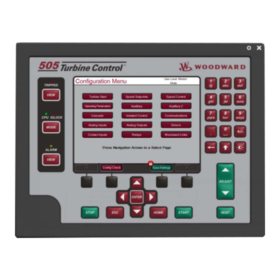
Page 135: Figure 5-8. Configuration Menu - Operation Mode (View Only)
Configuration menus - The Configuration ‘HOME’ page contains navigation buttons to all features and options of the 505. When the unit is in Configure Mode (IOLOCK) the background of all pages will be a blue gradient as shown below, in addition to the status in the upper right. -
Page 136: Overview Screen
Overview Screen Figure 5-10. Overview Screen The Overview screen will adapt to the configuration of the 505 and show all configured options. During normal run operation, this screen should provide the user with all of the primary turbine parameter values and operational status. -
Page 137: Speed Control Screen
Figure 5-11. Speed Control Screen The Speed Control screen will adapt to the configuration of the 505 and show all configured options. During normal run operation, this screen provides the user with all details that are related to the turbine when operating in speed control. -
Page 138: Controllers Screen
505 Digital Control for Steam Turbines The Valve Demand screen will adapt to the configuration of the 505 and show all configured options that can affect the final output demand to the valve. During normal run operation, this screen provides the user with a clear picture of what control or ramp is controlling the valve demand output. -
Page 139: Cascade Control Screen
Figure 5-14. Cascade Control Screen The Cascade Control screen will adapt to the configuration of the 505. During normal run operation, this screen provides the user with all details that are related to the cascade control loop. The cascade control output determines the setpoint for the speed control. -
Page 140: Analog Input Summary Screen
505 Digital Control for Steam Turbines The Auxiliary Control screen will adapt to the configuration of the 505. During normal run operation, this screen provides the user with all details that are related to the auxiliary control loop. The auxiliary control output goes to the LSS bus and can directly affect the HP valve demand output. -
Page 141: Contact Input Summary Screen
Figure 5-18. Analog Output Summary Screen The Analog Output Summary screen will display the status of all channels available on the 505 hardware. The fault status, function, device tag, engineering value and units are shown for each channel as well as navigation buttons for each channel that take the user to a page showing all parameters available for that output. -
Page 142: Relay Output Summary Screen
Figure 5-19. Relay Output Summary Screen The Relay Output Summary screen will display the status of all channels available on the 505 hardware. The coil status, function, and device tag are shown for each channel as well as navigation buttons for each channel that take the user to a page showing all parameters available for that output. -
Page 143: Starting Procedures (Start Curve Screen)
1. Press the RESET key to clear all alarms and trips. If the 505’s RESET CLEARS TRIP setting is programmed "YES", the 505's shutdown relay will reset or energize upon pressing the RESET key after a shutdown. -
Page 144: Overspeed Test Function (Speed Control Screen)
505 Digital Control for Steam Turbines Overspeed Test Function (Speed Control Screen) The 505’s Overspeed Test function allows an operator to increase turbine speed above its rated operating range to periodically test turbine electrical and/or mechanical overspeed protection logic and circuitry. -
Page 145: Figure 5-23. Internal (505) Overspeed Test
Woodward ProTech). In this mode the 505 internal overspeed trip will be changed to be just an alarm and the 505 will allow the speed to continue increasing up to the Overspeed Test Limit (rpm). If the 505 speed OR the Setpoint reaches the Overspeed Test Limit it will TRIP ... -
Page 146: Stop Key
Test Limit, the 505 will Trip on Overspeed If the Speed or the Setpoint reach the Overspeed Test Limit the 505 will issue a Trip In the configuration of Speed Setpoints be sure that the Overspeed Test Limit rpm value is above the expected Overspeed setting of the external safety overspeed protection device. -
Page 147: Figure 5-25. Alarm Screen
Each individual alarm condition is available through the Modbus links to monitor the control status. A common alarm indication is also provided. Relay indications can be programmed to indicate a 505 Common Alarm, in addition to the dedicated Alarm Relay output. - Page 148 Manual 26839V1 505 Digital Control for Steam Turbines Event ID DESCRIPTION MEANING Remote Droop Setting analog input failure detected (> 22 mA Remote Droop Fault or < 2 mA) Remote KW Setpoint Remote KW Setpt analog input failure (> 22 mA or < 2 mA) Failed Exhaust Pressure analog input failure detected (>...
- Page 149 AO_06 Readback Fault < 2 mA) 1- Display Backlight Fault 2- CPU OS fault Chassis Summary Alarm 3- 505 Internal temp is high (> 70 deg C) 4- Unit Calibration Fault (Factory Calibration) Turbine Tripped Turbine is tripped alarm indication Overspeed...
- Page 150 Manual 26839V1 505 Digital Control for Steam Turbines Event ID DESCRIPTION MEANING Selected PV 2 Level 1 ALM Signal Monitoring #2 passed alarm level 1 limit Selected PV 2 Level 2 ALM Signal Monitoring #2 passed alarm level 2 limit...
-
Page 151: Shutdown Summary
Manual 26839V1 505 Digital Control for Steam Turbines Event ID DESCRIPTION MEANING Selected PV 5 Level 2 ALM Signal Monitoring #5 passed alarm level 2 limit Selected PV 6 Level 1 ALM Signal Monitoring #6 passed alarm level 1 limit... - Page 152 Aux analog input failure detected (> 22 mA or < 2 Aux Input Failed Power Up Trip 505 lost power or the Configuration mode was exited Normal Shutdown Complete Controlled shutdown was performed and completed Trip Command from Modbus...
-
Page 153: Speed, Cascade, And Auxiliary Dynamics Adjustments
Each individual trip condition is available through the Modbus links to monitor the control status. A common trip indication is also provided. Relay indications can be programmed to indicate a 505 Shutdown Condition (energizes for a shutdown condition) or a Trip Relay (de-energizes for a shutdown/trip), in addition to the dedicated Emergency Trip Relay output. - Page 154 505’s gain must be very low to be added to the system gain required for system stability. In cases where a small change in the 505's output results in a large speed or load change (high mechanical gain) it may not be possible to take the 505's gains low enough to reach stable operation. In those cases the mechanical interface (actuator, linkage, servo, valve rack) design and/or calibration should be reviewed and changed to achieve a gain of one where 0–100% 505 output corresponds to 0–...
- Page 155 PID’s response to that of its control loop. There are multiple dynamic tuning methods available that can be used with the 505’s PIDs to assist in determining the gain terms that provide optimum control loop response times (Ziegler Nichols, etc.).
-
Page 156: Figure 5-28. Typical Response To Load Change
Manual 26839V1 505 Digital Control for Steam Turbines Figure 5-28. Typical Response to Load Change For additional information on PID settings, refer to Volume 2. Automated PID Dynamic Optimizer The Automated PID Dynamic Optimizer is a routine which allows the control to automatically analyze the system and calculate the P, I, and D terms. -
Page 157: Figure 5-29. Overview Of The Automated Pid Optimizer Routine
Manual 26839V1 505 Digital Control for Steam Turbines Figure 5-29. Overview of the Automated PID Optimizer Routine The Dynamics Optimizer screen is shown above. The current status is overviewed on the left hand side of the screen and results are given on the right. The menu bar on the bottom of the screen contains buttons which allow the configuration and operation of the Optimizer routine. -
Page 158: Figure 5-30. Optimization Routine Overview Trend
Manual 26839V1 505 Digital Control for Steam Turbines Figure 5-30. Optimization Routine Overview Trend Analysis Mode During the Analysis Mode, the optimizer begins by making small actuator movements which progressively increase until the measured process signal movement can be differentiated from signal noise. The initial movement direction (up or down) depends on system conditions. -
Page 159: Figure 5-31. Configuration Parameters 'Configure' Pop-Up
Manual 26839V1 505 Digital Control for Steam Turbines Once the routine is complete, the new gains can either be accepted by pressing the ‘Accept’ button within the Test Menu at the bottom of the screen. Alternatively, the gains can be rejected by pressing the ‘Reset Test’... - Page 160 Manual 26839V1 505 Digital Control for Steam Turbines Act Limit (online) (%) dflt= 10.0 (0.0, 100.0) This value limits how much the actuator demand will move during the Analysis Mode when the turbine is using Online dynamics. The percentage will limit the output +/- from the actuator position when the optimizer is enabled.
- Page 161 Manual 26839V1 505 Digital Control for Steam Turbines Most of the time, an alarm or fault indicates a problem with the steam turbine system that is outside of PID tuning. The descriptions below help identify what in the system may be causing the less than ideal control conditions.
- Page 162 Manual 26839V1 505 Digital Control for Steam Turbines Alarm 8 - Actuator movement is limited This alarm indicates that the actuator movement was limited during the Analysis Mode. This can result in a response that is not optimum, depending on the system conditions.
- Page 163 Manual 26839V1 505 Digital Control for Steam Turbines Faults Fault 1 – CLR_STATE was toggled TRUE This fault will only occur if the CLR_STATE input is toggled TRUE Some causes of this fault could be: The CLR_STATE input was toggled TRUE...
- Page 164 Manual 26839V1 505 Digital Control for Steam Turbines Fault 5 – Process movement greater than Process Limit This fault indicates that the process input exceed the Process Limit. Some causes of this fault could be: The Response Timeout is too long, the PID can't increase the output movement fast enough to counteract system drift.
- Page 165 Manual 26839V1 505 Digital Control for Steam Turbines Some solutions for this fault would include: Decrease Response Timeout if the system is much faster than the time-out Check the Droop input for noise and for the correct level.
-
Page 166: Chapter 6. Communications
Our experience has been that not all serial interfaces on laptops or Desktop PCs work the same. Many USB-to-Serial converters work, but some do not. To use a 505 Modbus port to monitor and/or operate, check the “Use Modbus” checkbox under the Configurations menu / Communications page. Monitor Only The three Modbus communication ports, are defaulted as read-only. -
Page 167: Figure 6-1. Ascii/Rtu Representation Of Three
Service Mode, if required. The 505 control is programmed to function as a slave unit only. As a slave unit, the 505 will only respond to a transaction request by a master device. The 505 can directly communicate with a DCS or other Modbus supporting device on a single communications link, or through a multi-dropped network. -
Page 168: Table 6-2. Modbus Frame Definition
Manual 26839V1 505 Digital Control for Steam Turbines Each message to or from a master has a defined structure called the message “frame”. A frame consists of the slave device address, a code defining the requested data, and error checking information. See Table 6-2. -
Page 169: Port Adjustments
Boolean Reads (Input Coils) Input coils are logical signals that are readable from, but not writable to, the 505 control. An example of a Boolean read value would be a turbine trip status indication. The input coil will have the value 1 if the statement in the description column is true and a 0 if false. -
Page 170: Table 6-7. Boolean Write Addresses
Analog Reads (Input Registers) Input registers are analog values that are readable from, but not writable to, the 505 control. An example of an analog read value would be turbine speed. The values of the input registers are stored internal to the control as floating point numbers representing engineering units (kPa or rpm). - Page 171 Manual 26839V1 505 Digital Control for Steam Turbines Addr Description Addr Description 0:0019 Arm Frequency Control 0:0073 * Disable Speed Forwarding 0:0020 Disarm Frequency Control 0:0074 0:0021 Sync Enable 0:0075 Momentarily Energize Relay 2 0:0022 Sync Disable 0:0076 Momentarily Energize Relay 3...
-
Page 172: Table 6-8. Boolean Read Addresses
Manual 26839V1 505 Digital Control for Steam Turbines Table 6-8. Boolean Read Addresses Addr Description Addr Description 1:0001 Alarm - MPU #1 Failed 1:0183 Inlet Pressure Configured 1:0002 Alarm - MPU #2 Failed 1:0184 Remote Control Configured 1:0003 Alarm - Cascade Input Failed... - Page 173 Manual 26839V1 505 Digital Control for Steam Turbines Addr Description Addr Description 1:0039 Modbus Alarm Acknowledge 1:0221 SPARE Alarm Exists (Common Alarm 1:0040 1:0222 * Trip - External Trip 10 Indication) 1:0041 Trip - External Trip 1:0223 * SD HP max...
- Page 174 Manual 26839V1 505 Digital Control for Steam Turbines Addr Description Addr Description 1:0078 Speed Sensor 2 Failed Override ON 1:0260 Alarm - AO_06 Readback Fault 1:0079 Overspeed Test Permissive 1:0261 Alarm - Chassis Temp 1:0080 Overspeed Test In progress 1:0262...
- Page 175 Manual 26839V1 505 Digital Control for Steam Turbines Addr Description Addr Description 1:0116 Remote Aux Is Active 1:0298 Alarm - spare_105 1:0117 Rmt Aux Is In Control 1:0299 Alarm - spare_106 1:0118 Rmt Aux Is Inhibited 1:0300 Alarm - spare_107...
-
Page 176: Table 6-9. Analog Reads
Manual 26839V1 505 Digital Control for Steam Turbines Addr Description Addr Description 1:0156 Relay 6 Energized 1:0338 Auxiliary 2 is Inhibited 1:0157 Relay 7 Energized 1:0339 Remote Aux 2 Is Enabled 1:0158 Relay 8 Energized 1:0340 Remote Aux 2 Is Active... - Page 177 Manual 26839V1 505 Digital Control for Steam Turbines Addr Description Units Multiplier 3:0011 Min Governor Speed Setpoint (RPM) 3:0012 Highest Speed reached 3:0013 Idle / Rated - Idle Speed (RPM) 3:0014 Idle / Rated - Rated Speed (RPM) 3:0015 Auto Seq - Idle 1 Speed Setpt (RPM)
- Page 178 Manual 26839V1 505 Digital Control for Steam Turbines Addr Description Units Multiplier 3:0051 * Spare E 3:0052 * Spare E 3:0053 * Spare E 3:0054 * Spare E 3:0055 * Spare E 3:0056 * Spare E 3:0057 * Spare E...
- Page 179 Manual 26839V1 505 Digital Control for Steam Turbines Addr Description Units Multiplier 3:0091 Analog Input 4 Configuration 3:0092 Analog Input 5 Configuration 3:0093 Analog Input 6 Configuration 3:0094 Analog Output 1 Configuration 3:0095 Analog Output 2 Configuration 3:0096 Analog Output 3 Configuration...
- Page 180 Manual 26839V1 505 Digital Control for Steam Turbines Addr Description Units Multiplier 3:0131 SPARE 3:0132 SPARE 3:0133 SPARE 3:0134 * Feed Forward Bias 3:0135 SPARE 3:0136 * Droop Setting 3:0137 * Autostart seq rate to Idle 1 rpm/s 3:0138 * Autostart seq CF Cold rte to Idle 2...
- Page 181 3:0200 Signal Monitoring #6 Input AI_SCALE 3:0201 Signal Monitoring #7 Scale Factor 1 3:0202 Signal Monitoring #7 Input AI_SCALE 3:0203 Signal Monitoring #8 Scale Factor 1 3:0204 Signal Monitoring #8 Input AI_SCALE *—Denotes differences between 505 and 505 Enhanced. Woodward...
-
Page 182: Table 6-10. Analog Write Addresses
Table 5-2. 505 Controlling Parameters The controlling parameter status of the 505 uses an Analog Read register (3:0001) to identify the parameters that are in control. This variable follows what is displayed on the controlling parameter screen, under the ‘CONT’ key. The variable gives the current status of the control and is defined in the following table. -
Page 183: Table 6-12. Analog Input Configuration
Manual 26839V1 505 Digital Control for Steam Turbines Table 6-12. Analog Input Configuration Value Description Value Description --- Not Used --- Remote Droop Remote Speed Setpoint Remote KW Setpoint Synchronizing Input Exhaust Pressure Input Sync / Load Share Spare 19... -
Page 184: Table 6-14. Relay Configured As Level Switch
Manual 26839V1 505 Digital Control for Steam Turbines Table 6-14. Relay Configured As Level Switch Value Description Value Description --- Not Used --- LSS Value Actual Speed HP Valve Demand Output Speed Setpoint HP2 Valve Demand Output KW Input Inlet Pressure... -
Page 185: Specific Address Information
Manual 26839V1 505 Digital Control for Steam Turbines Analog Read addresses 3:0106—0117 give the configuration value of the contact inputs in order. The configuration for the contact inputs are defined in the table below. Table 6-16. Contact Input Configurations Value... - Page 186 (6015/100 = 60.15). A Directly Entered Cascade Set Point (4:0002) of 61.5 would be sent across the link as 6150 and the 505 automatically divides the value by the Casc Scale Factor and uses the value of 61.5 as the set point desired.
-
Page 187: Chapter 7. Product Support And Service Options
An Authorized Independent Service Facility (AISF) provides authorized service that includes repairs, repair parts, and warranty service on Woodward's behalf. Service (not new unit sales) is an AISF's primary mission. A Recognized Turbine Retrofitter (RTR) is an independent company that does both steam and gas turbine control retrofits and upgrades globally, and can provide the full line of Woodward systems and components for the retrofits and overhauls, long term service contracts, emergency repairs, etc. -
Page 188: Returning Equipment For Repair
All repair work carries the standard Woodward service warranty (Woodward Product and Service Warranty 5-01-1205) on replaced parts and labor. -
Page 189: Replacement Parts
The unit serial number, which is also on the nameplate Engineering Services Woodward offers various Engineering Services for our products. For these services, you can contact us by telephone, by email, or through the Woodward website. Technical Support ... -
Page 190: Technical Assistance
505 Digital Control for Steam Turbines Technical Assistance If you need to contact technical assistance, you will need to provide the following information. Please write it down here before contacting the Engine OEM, the Packager, a Woodward Business Partner, or the Woodward factory: General... -
Page 191: A Mode Worksheets
Manual 26839V1 505 Digital Control for Steam Turbines Appendix A. 505 Configuration Mode Worksheets Governor Serial Number ______________________ Application ________________________________ Date ___________ For details on individual settings, refer to Chapter 4. TURBINE START Start Mode Manual Start Semiautomatic Start Automatic Start... - Page 192 Manual 26839V1 505 Digital Control for Steam Turbines Warm Idle 1 Delay Hot Idle 1 Delay Use Idle 2 Cold Rate to Idle 2 RPM/s Warm Rate to Idle 2 RPM/s Hot Rate to Idle 2 RPM/s Idle 2 Setpt (rpm)
- Page 193 Manual 26839V1 505 Digital Control for Steam Turbines Off-line Slow Rate (rpm/s) RPM/s On-line Slow Rate (rpm/s) RPM/s Remote Setpoint Speed Remote Speed or kW Setpoint Maximum Units/s Rate Use Critical Speeds? Critical Speed Rate RPM/s Critical Speed 1 Min...
- Page 194 Manual 26839V1 505 Digital Control for Steam Turbines Use MW as Load Units? Use Load Droop? Max Load Primary Generator Load Signal Secondary Generator Load Signal Primary Sync/Load Share Signal Secondary Sync/Load Share Signal Primary Sync Signal Secondary Sync Signal...
- Page 195 Manual 26839V1 505 Digital Control for Steam Turbines Use as Controller? Setpoint Initial Value Units Droop % PID Proportional Gain % PID Integral Gain rps PID Derivative Ratio % Tie Breaker Open Aux Disable Gen Breaker Open Aux Disable Use Remote Setpoint...
- Page 196 Manual 26839V1 505 Digital Control for Steam Turbines Max Speed Setpoint Rate (rpm/s) RPM/s Cascade Droop % PID Proportional Gain % PID Integral Gain rps PID Derivative Ratio % Use Remote Cascade Setpoint Remote Cascade Max Rate Units/s Configured Units of Measure...
- Page 197 Manual 26839V1 505 Digital Control for Steam Turbines Modbus Ethernet Link 2 Ethernet Protocol TCP UDP 5001 Device Address (1-247) Enable Write Commands Modbus Ethernet Link 3 Ethernet Protocol TCP UDP 5002 Device Address (1-247) Enable Write Commands ANALOG INPUTS Analog Input 01 Input Function...
- Page 198 Manual 26839V1 505 Digital Control for Steam Turbines Modbus Multiplier Decimals Displayed Analog Input 05 Input Function 4 mA Value Units 20 mA Value Units Loop Powered Device Tag Units Modbus Multiplier Decimals Displayed Analog Input 06 Input Function 4 mA Value...
- Page 199 Manual 26839V1 505 Digital Control for Steam Turbines Device Tag Units Enable Readback Fault Analog Output 02 Output Function 4 mA Value Units 20 mA Value Units Device Tag Units Enable Readback Fault Analog Output 03 Output Function 4 mA Value...
- Page 200 Manual 26839V1 505 Digital Control for Steam Turbines Use Actuator Fault Shutdown Invert Output Device Tag HP2 Offset Readout Function 4 mA Value Units 20 mA Value Units Enable Readback Fault Device Tag Units Actuator 02 Function Range 4-20 mA...
- Page 201 Manual 26839V1 505 Digital Control for Steam Turbines Device Tag Invert Logic? Contact Input 06 Input Function Device Tag Invert Logic? Contact Input 07 Input Function Device Tag Invert Logic? Contact Input 08 Input Function Device Tag Invert Logic? Contact Input 09...
- Page 202 Manual 26839V1 505 Digital Control for Steam Turbines Device Tag Invert Logic? Contact Input 17 Input Function Device Tag Invert Logic? Contact Input 18 Input Function Device Tag Invert Logic? Contact Input 19 Input Function Device Tag Invert Logic? Contact Input 20...
- Page 203 Manual 26839V1 505 Digital Control for Steam Turbines Relay Output 05 Use as Level Switch? Function Device Tag Invert Output ON Level Units OFF Level Units Relay Output 06 Use as Level Switch? Function Device Tag Invert Output ON Level...
- Page 204 Manual 26839V1 505 Digital Control for Steam Turbines Using 2 VariStroke II Actuators? When Actuator Outputs have been (In Service) Calibrated and Stroked, record values here. Default 505 Unit #1 Value in 505 Actuator # 1 mA at Minimum Position *4.00...
-
Page 205: Declarations
Manual 26839V1 505 Digital Control for Steam Turbines Declarations Woodward... - Page 206 Manual 26839V1 505 Digital Control for Steam Turbines Woodward...
- Page 207 Email and Website—www.woodward.com Woodward has company-owned plants, subsidiaries, and branches, as well as authorized distributors and other authorized service and sales facilities throughout the world. Complete address / phone / fax / email information for all locations is available on our website.
Need help?
Do you have a question about the 505 and is the answer not in the manual?
Questions and answers