
Related Manuals for Woodward 8280-464


Summary of Contents for Woodward 8280-464
- Page 1 Product Manual 02883 (Revision B) Original Instructions 723PLUS Digital Speed Control for Reciprocating Engines—Process Control 8280-464, 8280-465 Installation and Operation Manual...
- Page 2 Revisions—Changes in this publication since the last revision are indicated by a black line alongside the text. Woodward reserves the right to update any portion of this publication at any time. Information provided by Woodward is believed to be correct and reliable. However, no responsibility is assumed by Woodward unless otherwise expressly undertaken.
- Page 3 Droop ........................104 Power-Up Diagnostics ..................104 6. T ............. 105 HAPTER ROUBLESHOOTING General ....................... 105 Troubleshooting Procedure ................105 Control Test and Calibration ................105 Conclusion of Test and Calibration Procedures ..........109 Woodward...
- Page 4 Product Support Options ..................110 Product Service Options ..................110 Returning Equipment for Repair .................111 Replacement Parts .....................111 Engineering Services ..................112 Contacting Woodward’s Support Organization ..........112 Technical Assistance ..................113 A. S ......114 PPENDIX ERIAL OMMUNICATION IRING ...
- Page 5 Figure B-15b. Troubleshooting Flowchart (2 of 2) ..........134 Figure B-16. Direct Wired Network ..............136 Figure B-17. Network Wired Via Stubs ............... 136 Table 1-1. LINKnet Modules (Summary) ..............3 Table 1-2. LINKnet Modules (Address) ..............3 Woodward...
- Page 6 Start-up On- and off-highway Mobile Applications: Unless Woodward's control functions as the supervisory control, customer should install a system totally independent of the prime mover control system that...
- Page 7 Do not touch the components or conductors on a printed circuit board with your hands or with conductive devices. To prevent damage to electronic components caused by improper handling, read and observe the precautions in Woodward manual 82715 , Guide for Handling and Protection of Electronic Controls, Printed Circuit Boards, and Modules.
- Page 8 723PLUS/Process Control Manual 02883 Woodward...
-
Page 9: General Information
General Information Introduction This manual describes the Woodward 723PLUS Digital Industrial Speed/Process Control, models 8280-464 (low voltage) and 8280-465 (high voltage). Declaration of Incorporation In accordance with the EMC Directive 89/336/EEC and its amendments, this controlling device, manufactured by the Woodward Governor Company, is applied solely as a component to be incorporated into an engine prime mover system. -
Page 10: Control Options
1000 Hz tandem actuator outputs 0–1 or 4–20 mA analog outputs 4–20 or 0–200 mA actuator outputs Magnetic pickup inputs should only be used when operating speeds provide at least 400 Hz magnetic pickup frequency. Woodward... -
Page 11: Plus Digital Speed Control Accessories
The two communication ports (J2 and J3) and the LON #1 data channel allow for digital communications between external Modbus compatible devices, Servlink devices, and Woodward LINKnet I/O modules. Port J2 is a dedicated port for Servlink clients like Watch Window and Control View. The LON #1 channel has been designated for use with up to 18 LINKnet modules. -
Page 12: Figure 1-2. 723Plus Digital Speed Control
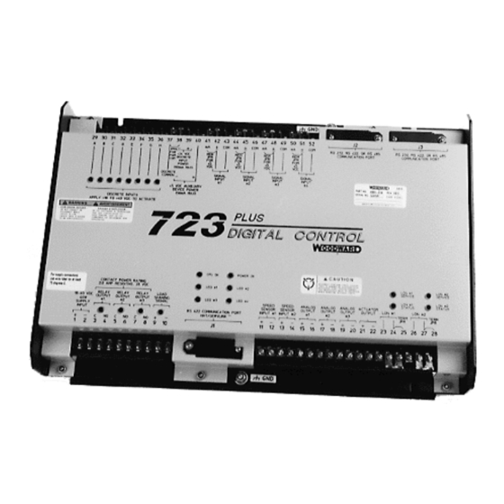
723PLUS/Process Control Manual 02883 Figure 1-2. 723PLUS Digital Speed Control Woodward... -
Page 13: Figure 1-3. Watch Window Display
Manual 02883 723PLUS/Process Control Figure 1-3. Watch Window Display Woodward... -
Page 14: Figure 1-4. Hand Held Programmer
723PLUS/Process Control Manual 02883 Figure 1-4. Hand Held Programmer Woodward... -
Page 15: Figure 1-5. Typical 723Plus Connections
Manual 02883 723PLUS/Process Control Figure 1-5. Typical 723PLUS Connections Woodward... -
Page 16: Figure 1-6A. Control Wiring Diagram
723PLUS/Process Control Manual 02883 Figure 1-6a. Control Wiring Diagram Woodward... -
Page 17: Figure 1-6B. Control Wiring Diagram
Manual 02883 723PLUS/Process Control Figure 1-6b. Control Wiring Diagram Woodward... -
Page 18: C Hapter 2. I Nstallation
avoidance of vibration; selection of a location that will provide an operating temperature range of –40 to +70 °C (–40 to +158 °F). The control must NOT be mounted on the engine. Woodward... -
Page 19: Electrical Connections
25 mm (1 inch). The other end of the shields must be left open and insulated from any other conductor. DO NOT run shielded signal wires along with other wires carrying large currents. See Woodward application note 50532, Interference Control in Electronic Governing Systems for more information. -
Page 20: Figure 3-1. 723Plus Control Internal Jumpers
723PLUS/Process Control Manual 02883 Figure 3-1. 723PLUS Control Internal Jumpers Woodward... - Page 21 Remove 6 mm (1/4 inch) of insulation from the inner conductors. Installations with severe electromagnetic interference (EMI) may require additional shielding precautions. Contact Woodward for more information. Power Supply (Terminals 1/2) Power supply output must be low impedance (for example, directly from batteries).
- Page 22 The relay changes state if any configured shutdown condition has occurred without being cleared or reset. The state of the contact can be configured as either close on shutdown or open on shutdown. If power to the control is lost, the contact will open. Woodward...
- Page 23 To prevent possible damage to the control or poor control performance resulting from ground loop problems, we recommend using current-loop isolators if the 723PLUS control's analog inputs and outputs must both be used with non-isolated devices. A number of manufacturers offer 20 mA loop isolators. Woodward...
- Page 24 0–200 mA or 4–20 mA. If the hardware jumper is changed, the software settings must also be changed. LON #1 and LON #2 (Terminals 23—28) The 723PLUS control provides two separate LON communication channels for ® communicating with Echelon networks. Woodward...
- Page 25 Manual 02883 723PLUS/Process Control ™ LON #1 is used to connect up to eighteen Woodward LINKnet I/O modules. These modules provide values for temperature, 4 to 20 mA inputs, and discrete inputs for availability to the two serial communication ports (J2 and J3).
- Page 26 Be sure the mechanical governor is properly set up to assume control in the event of an electrical system failure. The mechanical governor must NOT be set up to assume control during normal electrical governor operation. Such interaction produces undesirable instability. Woodward...
- Page 27 Lower is limited to the minimum speed limit. With the contacts open (discrete input in the FALSE state), the control will stop lowering the speed reference. Maintained simultaneous closure of this Lower input contact, along with the Raise input contact, enables the Remote Speed input. Woodward...
- Page 28 Input #1, in conjunction with Signal Input #2, allows an external differential process to adjust engine speed for differential process (deadband or cascade) control. No connection is required to this input if this function is not needed by the application. Woodward...
- Page 29 A failure of the input signal is detected for input values less than 2.0 mA (0.5 Vdc) and for values exceeding 21 mA (5.25 Vdc). A detected failure will remain until the failure is repaired and an Alarm Reset is issued. Woodward...
- Page 30 (0.5 Vdc). A detected failure will remain until the failure is repaired and an Alarm Reset is issued. RS-422 Communication Port (J1) Port J1 is intended for use with the Woodward ST2000 Hand Held Programmer (part number 9907-205), Watch Window software (part number 8923-932), or Control View software (part number 8928-056). The RS-232/RS-422 download cable (part number 5416-870) or Hand Held Programmer plug into communication port J1 of the control.
- Page 31 12 mA from a particular output, the Modbus device must send a value 12000). The relay outputs will energize when the state of the correct address is set to TRUE. A FALSE state will cause the relay output to de- energize. Woodward...
- Page 32 If a resistance less than infinite is obtained, remove the connections from each terminal one at a time until the resistance is infinite. Check the line that was removed last to locate and repair the ground fault. Woodward...
-
Page 33: Introduction
Watch Window PC Interface Watch Window was developed by Woodward to be a Servlink client software product to provide a generic PC interface to any 723PLUS control and is a very powerful setup, testing, and troubleshooting tool. Watch Window provides a... -
Page 34: Plus Control View
Help file provided with the Watch Window install software. 723PLUS Control View Woodward has created Control View as a PC interface for the 723PLUS Process Control. This custom graphical user interface is a Servlink client that has all 723PLUS Process Control tunable values and monitoring parameters laid out in an intuitive manner. - Page 35 While in configure mode, the controller locks out all other input and output processing. This means that if the controller is put in configuration mode while its control device is still active (e.g. the engine is still running) results could be unpredictable. Woodward...
- Page 36 symbol will appear at the right edge of main lists which contain a sub-screen list. This facilitates moving to sub-screens. Left click when the cursor is over the desired screen or sub-screen name to move directly to that screen. Woodward...
- Page 37 Mode. This rule does not apply when in Configuration Mode. Click the = sign or press the enter key to accept newly typed settings. All values in either mode must be within “max” and “min” limits fixed in the control software. Woodward...
- Page 38 This quick menu will appear when you right click on a gauge (or a group of gauges) that has a changeable range. There are always multiple quick options and a manual option. If the program is set to save settings on close, new gauge settings will automatically be saved when the program is closed. Woodward...
- Page 39 To prevent possible damage to the engine resulting from improper control settings, make sure you save the set points before removing power from the control. Failure to save the set points before removing power from the control causes them to revert to the previously saved settings. Woodward...
- Page 40 A digital display of the current x (curve input) and y (curve output) values in engineering units is included. Y in this example is the fuel limit (as a % fuel demand) based on engine speed. X is engine speed. Woodward...
- Page 41 Adjustments to both the x and y breakpoint values can be made, as described earlier, by using the “turtle” and “rabbit” arrows or by typing in values and pressing the = key for the selected point. All breakpoints of all curves can be adjusted in this manner from the curve graph screens. Woodward...
- Page 42 This is especially useful when tuning an engine and when different fluctuations need to be seen and dealt with analytically. Here is an example showing some analog inputs as well as a static value: Woodward...
- Page 43 Note that if the log file exists it is automatically appended to (data is only added to the end). If you wish to start with a fresh log, put in a file name that does not exist, and it will be automatically created when logging is started. Woodward...
- Page 44 The estimate is based on every value being written at its Maximum Axis Value. In most cases the actual data rate should be less. If logging the time is enabled, then every time stamp is evaluated as having three decimal places for estimation purposes. Woodward...
- Page 45 Line), as well as how many tick marks are placed on the Y Axis. Decimals: Controls how many decimal places are shown for all data displayed on the graph. This is also used to control how many decimals places are used when data is written to a log file. Woodward...
- Page 46 Extensive on-line Help is available. The above instructions are given as an overview only and are not intended to supplant the normal use of the on-line Help. On-line Help is interactive. Just click the Topic to open that Help page and disclose links to related Help Topics. Woodward...
-
Page 47: Hand Held Programmer And Menus
Press the “ID” key to display the part number and revision level of the software in the control. Refer to this number and revision level in any correspondence with Woodward (write this information in the Programming Checklist, Appendix D). -
Page 48: Service Menus
To prevent possible damage to the engine resulting from improper control settings, make sure you save the set points before removing power from the control. Failure to save the set points before removing power from the control causes them to revert to the previously saved settings. Woodward... - Page 49 Scrolls left through line of display. SPACE Scrolls right through line of display. ENTER Used when entering exact values and accessing Configure. = (equals) For entering exact values (within 10%). (decimal) To select Configure. Also used for entering decimal exact values. Woodward...
-
Page 50: Configuration Menu Descriptions
Reverse-acting actuators require decreased current to increase fuel (reverse-acting actuators should always incorporate a mechanical ballhead backup governor, such as the Woodward EGB). USE 2nd DYNAMICS should be set TRUE to bring into view the 2nd SPEED DYNAMICS menu when the 2nd Dynamics discrete input is TRUE and permit the use of the 2nd Dynamics function. - Page 51 TORQUE LIMIT CURVE menu and permit the use of the Torque Fuel Limit. The Torque Fuel Limit function provides five tunable limits of the fuel demand at five tunable engine speed breakpoints. Set to FALSE to disable the Torque Limit function and conceal the TORQUE LIMIT CURVE menu. Woodward...
- Page 52 Set TRUE to enable the notch filter and disable the torsional filter. Set to FALSE to disable the notch filter and permit the torsional filter to be enabled. 17. ENABLE TORS LIMITER should be set to TRUE to enable a tunable Torsional Fuel Limiter. Set FALSE to disable this Fuel Limiter. Woodward...
- Page 53 The number of gear teeth is used by the control to convert pulses from the speed-sensing device to engine rpm. To prevent possible serious injury from an overspeeding engine, make sure the control is properly programmed to convert the gear-tooth count into engine rpm. Improper conversion could cause engine overspeed. Woodward...
- Page 54 11. MPU ALARM ARM TIME (SEC) is the time delay to wait before latching armed the MPU Failure Alarm & Shutdown functions once a valid MPU signal is detected. Opening the “Close to Run” contact resets the latch block to prevent MPU Failure Alarm and Shutdown conditions from occurring with normal stops. Woodward...
- Page 55 10. HIGH SPEED LEVEL sets the condition which will occur when the engine speed rises above the HI SPEED SETPOINT. This condition may be enabled as a Shutdown, Alarm, or both, by selecting TRUE in the appropriate menu. Woodward...
- Page 56 ON TORSION LIMIT is set to TRUE to actuate Relay Output #3 when this fuel limit is in control and to display status on the DISPLAY INDICATOR menu. Set to FALSE to prevent Relay Output #3 actuation and display of limit status. Woodward...
- Page 57 TORSIONAL FILTER service menu . Default setting is 1% of rated rpm. HI TORSION DELAYEnter the delay time in seconds that the torsional level is above the TORSION LEVEL SETPT before the HIGH TORSION LEVEL shutdown is activated. Woodward...
- Page 58 HI SPEED SETPOINTEnter the engine speed fault level (rpm) required to trigger the HI SPEED LEVEL alarm. HI SPEED DELAYEnter the delay time (in seconds) to wait before the HI SPEED LEVEL alarm is issued after engine speed exceeds the HI SPEED SETPT. Woodward...
- Page 59 15. PROCESS DIFF DELAY is the delay time in seconds that the Process 1 minus Process 2 differential level is above the PROC DIFF HI LEVEL or below the PROC DIFF LO LEVEL set points before the PROCESS DIFF HIGH and PROCESS DIFF LOW alarm conditions are activated. Woodward...
- Page 60 PORT 2 ADDRESS determines the ports multidrop Servlink address from 1 to 15. PORT 3 ADDRESS determines the ports multidrop Modbus address from 1 to 247. PORT3 MODE determines if port J3 will use the Modbus ASCII or Modbus RTU mode: 1 = ASCII 2 = RTU Woodward...
- Page 61 TRUE will scale the output for 4 to 20 mA. Note that an internal jumper must be configured if this item is changed. Analog Output #3 is hard configured as the Speed Control Actuator output and does not offer an output configuration selection. Woodward...
-
Page 62: Service Menu Descriptions
This shutdown will only indicate if it has been activated in the CFIG SHUTDOWN menu. 3-SPD #1 AND #2 FAIL displays the present condition of the latched shutdown. This shutdown will only indicate if it has been activated in the CFIG SHUTDOWN menu. Woodward... - Page 63 This shutdown will only indicate if it has been activated in the CFIG SHUTDOWN menu. 19. ALARM RESET is used to reset all latched alarms and shutdowns once the condition which triggered the alarm or shutdown has been cleared. Toggle TRUE then FALSE to activate the reset. Woodward...
-
Page 64: Alarm Menu
This alarm will only indicate if it has been activated in the CFIG ALARM menu. 14. 13-PROCESS #1 LOW displays the present condition of the latched alarm. This alarm will only indicate if it has been activated in the CFIG ALARM menu. Woodward... - Page 65 Width. This makes the control dynamics fast enough to minimize engine- speed overshoot on start-up and to reduce the magnitude of speed error when loads are changing. This allows a lower gain at steady state for better stability and reduced steady-state actuator linkage movement. (See Figure 4-2.) Woodward...
- Page 66 Be prepared to change the dynamics settings since the actuator bump transient may stimulate instability. BUMP ENABLE must be set TRUE to enable the BUMP ACT function. See the ACTUATOR BUMP menu. Woodward...
-
Page 67: Figure 4-2. Control Gain As A Function Of Speed Error
Manual 02883 723PLUS/Process Control Figure 4-2. Control Gain as a Function of Speed Error Figure 4-3. Control Gain as a Function of Control Output Woodward... -
Page 68: Figure 4-4. Typical Transient Response Curves
723PLUS/Process Control Manual 02883 Figure 4-4. Typical Transient Response Curves Woodward... -
Page 69: Figure 4-5. Speed Filter
11. RESET compensates for the lag time of the engine. It adjusts the time required for the control to return the speed to zero error after a disturbance. Reset is adjusted to prevent slow hunting and to minimize speed overshoot following a load disturbance. Woodward... - Page 70 Be prepared to change the dynamics settings since the actuator bump transient may stimulate instability. BUMP ENABLE must be set to TRUE to enable the BUMP ACT function. See the ACTUATOR BUMP menu. Woodward...
- Page 71 TRUE. When set to FALSE the function is disabled. ENG SENSOR WEIGHT is the inertia ratio setting between the engine inertia and the system inertia. Set the value equal to engine inertia divided by (engine inertia + driven load inertia). Woodward...
-
Page 72: Figure 4-6. Notch Filter
The notch filter is enabled when CFIG OPTION menu items USE TORSION FILTER and USE NOTCH FILTER are set to TRUE, and TORSIONAL FILTER menu item ENABLE TORS FILTER is set to TRUE. Otherwise the notch filter is disabled. Woodward... -
Page 73: Figure 4-7. Start Limit Function
Start Speed to idle or rated, whichever is selected and permissive, begins when the engine accelerates to Start Speed. The ramp time is the accel ramp time setting or the decel ramp time setting as determined by the idle/rated selection and permissives. Woodward... - Page 74 This menu is used to setup the Deadband Process Control. The CFIG OPTION menu item USE CASCADE PROCESS must be set to FALSE, and the PROCESS CTRL OPTION must not be set at zero to bring into view the DB PROCESS CONTROL menu. Woodward...
- Page 75 Process #2 Input differential in engineering units. 14. PROCESS REFERENCE (EU) is a display only of the Process Reference in engineering units. 15. PROCESS REM REF (EU) is a display only of the Remote Process Reference in engineering units. Woodward...
- Page 76 12. PROCESS #1 FILTER adjusts the cutoff frequency of a low pass filter for Analog Input #1 which may be used to smooth out the signal by ignoring noise from the input. To use this feature set the cutoff frequency below 15.9 Hz. Set at 15.9 Hz or higher to disable filter. Woodward...
-
Page 77: Figure 4-8. Torque Limit Curve
A five-point curve is constructed for rpm versus Fuel Demand (refer to Figure 4-8). The ‘X’ values are the Breakpoints, and the ‘Y’ values are the Fuel Limit at the Breakpoints. All values between the designated breakpoints are interpolated. Figure 4-8. Torque Limit Curve Woodward... -
Page 78: Figure 4-9. Droop Curve
This establishes the 0% internal load measurement for droop. FUEL DEMAND @ MAX LD should be set to the percent fuel demand when the engine is operating at rated-speed/full-load. This establishes the 100% internal load measurement for droop. Figure 4-9. Droop Curve Woodward... - Page 79 REMOTE SPD @ 4 mA (rpm)Enter the preferred engine speed reference set point in rpm at 4 mA from the Remote Speed Reference input device. If a voltage sensing device is provided, enter the input rpm at 1 Vdc. Woodward...
- Page 80 (or 20 mA if configured) with the fuel demand at 100 percent. These settings are fixed and not tunable. ACTUATOR OUT 2 MIN is adjusted to the engineering units which will output 4 mA (or 0 mA if so configured) at Analog Output #4. Woodward...
- Page 81 13. AO 1 OFFSET adjusts the Analog Output #1 mA minimum. 14. AO 1 SPAN adjusts the Analog Output #1 mA maximum. 15. AO 2 OFFSET adjusts the Analog Output #2 mA minimum. 16. AO 2 SPAN adjusts the Analog Output #2 mA maximum. Woodward...
- Page 82 J2 is set for a 38400 baud rate, then port 3 cannot be 19200. Also, if port J3 is set for a 19200 baud rate, then port 2 cannot be a 38400. If port J3 is set for a 38400 baud rate, then port 2 cannot be 19200. Woodward...
- Page 83 The following exception error codes will be displayed: Messages sent by a slave and displayed by Service. No error Illegal function Illegal data address Messages displayed by Service. Checksum error 10 Message garbled The Alarm Reset will reset all of the exception errors. Woodward...
- Page 84 LINKnet nodes only reset their hardware switch addresses on power- AI “x” CH “x” - mA INPUT is a display only of the Channel “x” mA input current for the selected AI Module. This value times 1000 is sent to Modbus. Woodward...
- Page 85 AO1 CH “x” OFFSET sets the minimum current at the AO1 Module Channel “x” minimum input value, in engineering units. AO1 CH “x” SPAN sets maximum current at the AO1 Module Channel “x” maximum input value, in engineering units. Woodward...
- Page 86 AI2-PROCESS IN #2 shows the value, in mA, of the Process Input #2 signal. This value times 1000 is sent to Modbus. The mA value is after the effect of the offset and span in the I/O CALIBRATION menu. Woodward...
- Page 87 Max Fuel Limit. ON EXT FUEL LIMIT will show TRUE when the fuel demand is being limited by the External Fuel Limit. ON TORSION LIMIT will show TRUE when the fuel demand is being limited by the Torsional Fuel Limit. Woodward...
- Page 88 12. DB PROC CTRL ACTIVE will show TRUE when the Deadband Process Control is actively controlling the engine speed reference. 13. SPD SENSOR 1 ACTIVE will show TRUE when speed sensor input #1 is actively used by the control. Woodward...
- Page 89 PROCESS INPUT #2 displays the present process #2 input in engineering units. 10. PROCESS DIFFERENCE displays the present process #1 minus process #2 input difference in engineering units. 11. PROCESS REFERENCE displays the present process reference in engineering units. Woodward...
- Page 90 DO1 CH1 FORCE is set to TRUE to force Discrete Output 1, Channel 1 to the energized state. Set value to FALSE to force the Discrete Output 1, Channel 1 to the de-energized state. Woodward...
- Page 91 Channel 6 to the de-energized state. 15. DO2 CH7 FORCE is set to TRUE to force Discrete Output 2, Channel 7 to the energized state. Set value to FALSE to force the Discrete Output 2, Channel 7 to the de-energized state. Woodward...
- Page 92 Channel 6 to the de-energized state. DO3 CH7 FORCE is set to TRUE to force Discrete Output 3, Channel 7 to the energized state. Set value to FALSE to force the Discrete Output 3, Channel 7 to the de-energized state. Woodward...
- Page 93 Channel 8 to the de-energized state. Be sure to set the ‘FORCE DISCRETE OUTS’ on the CFIG Option menu back to FALSE when discrete output testing is completed. Failure to do so will hold the output in the last forced state. Woodward...
-
Page 94: Introduction
Fuel Limit. The start speed reference, if configured, must be set above cranking speed but below the speed achieved with the start fuel limit setting (light-off speed). We recommend trying both hot and cold starts to determine a final setting. Woodward... -
Page 95: Dynamic Adjustments
A final value of Reset should be between 1.0 and 2.0 for most large engines. If the Reset value exceeds 2.0, but this procedure continues to improve performance, increase the Compensation set point 50% and repeat the procedure. Woodward... - Page 96 Select the Maximum Fuel Limit set point on the Fuel Limiter Menu. Set at approximately 10% over the full load output if desired, otherwise leave at 100%. We recommend you check the operation from both hot and cold starts to obtain the optimum stability under all conditions. Woodward...
-
Page 97: Speed Adjustments
Disconnect the Hand Held Programmer from the control (if applicable). Control View or Watch Window may remain connected or removed from the control at the end user’s discretion. Close the cover over J1 and re-tighten the retaining screw if connection is removed. Woodward... -
Page 98: C Hapter 5. D Escription Of O Peration
Control View or Watch Window may remain installed or disconnected at the end user’s discretion. The speed sensor inputs (8280-464 and 8280-465 controls) contain a special tracking filter designed for reciprocating engines, which minimizes the effects of firing torsionals so that the actuator will not respond to speed sensor changes it cannot control with the fuel. - Page 99 The Cascade Process Control dynamics are fixed as entered and do not include the various dynamic choices described above for the speed control. Woodward...
-
Page 100: Speed Input
The torsional filtering function requires two speed sensors. The function is disabled if either of the speed sensors fail. A software switch in the Torsional Filter menu can also be used to disable the function and return to the HSS selection of the two speed sensors. Woodward... -
Page 101: Notch Filter Function
It is used to set a maximum position of the actuator. This is generally used to prevent engine overloading or other situations where the maximum fuel delivered to the engine should be limited. The function can be disabled by adjusting the Max Fuel Limit to 100 percent. Woodward... -
Page 102: Start Limit Function
Start Fuel Limit Function is re-armed for trigger during the next start. The start fuel limit function also works on reverse-acting systems. The function can be disabled by adjusting the Start Fuel Limit to a value of 100. Figure 6-2. Start Limit Function Woodward... -
Page 103: Fuel Limiting Function
These functions are also disabled if the input signal is failed. These functions can also be enabled or disabled by software at the EXT FUEL Limit Curve menu and the Torque Limit Curve menu. Figure 6-3. Fuel Limit Breakpoints Woodward... -
Page 104: Alarm Reset
Watch Window, Control View, or with the Hand Held programmer. Toggling the Alarm Reset discrete input TRUE, then FALSE, issues the Alarm Reset command. An Alarm Reset is also issued when power is applied to the 723PLUS. And finally, the control issues an Alarm Reset during startup (when configured). Woodward... -
Page 105: Speed And Process Reference And Ramps
(e.g., spark gas recip engines). This Start reference is selected, at a very fast rate, by control power- up, engine not running, or engine cranking. When configured TRUE, the Start reference is given first priority over all other references. Woodward... - Page 106 The 4 mA Remote Reference set point may be set to a lower or higher speed than the 20 mA set point, providing for either direct or reverse-acting remote speed setting. Woodward...
-
Page 107: Figure 6-4. Remote Speed Reference
The process reference raise/lower, remote process reference, and ramp functions are active when the process control is enabled. Read this section carefully to be sure your sequencing provides the proper operating modes. Woodward... - Page 108 Do not enable the remote process reference prior to starting if the idle speed reference is the preferred reference for starting. Woodward...
- Page 109 TRUE. Otherwise the process reference follows the failed or out-of-range remote input value, at the process raise or lower rate, until a process raise or lower limit is reached. Woodward...
-
Page 110: Process Control
Process Rev Acting to TRUE on the CFIG Option menu. Set to TRUE for applications where increasing speed decreases the process variable (e.g., Suction Pressure control). Set to FALSE for applications where increasing speed increases the process variable (e.g., Flow or Discharge Pressure control). The default setting is FALSE. Woodward... - Page 111 Cascade PID control signal decreases the speed reference. To reverse the action of the Cascade PID Process control, set the Spd Ref @ 0% PID value ABOVE the Spd Ref @ 100% PID value on the Cascade Proc Ctrl menu. Woodward...
-
Page 112: Droop
The diagnostics take about 20 seconds after the control is powered on. A failure of the test will turn off all outputs from the control. If diagnostic testing is successful, the green CPU OK indicator on the control cover will light. Woodward... -
Page 113: C Hapter 6. T Roubleshooting
Programmer (if applicable) has failed. If so, try this step with another Hand Held Programmer. If the test still fails, replace the 723PLUS control. If the test passes with the second Hand Held Programmer, replace the first Hand Held Programmer. Woodward... - Page 114 44 and 45. Connect a dc voltmeter across terminals 45(+) and 46(–). Optionally, a mA meter may be installed in series with the 4 to 20 mA source. Woodward...
- Page 115 Hand Held Programmer, Control View, or Watch Window. Select EXT FUEL LIMIT IN. The EXT FUEL LIMIT IN value should be equal to the EXT FUEL LMT @ 20mA value set previously in the SET ANALOG INPUTS menu. Woodward...
- Page 116 The value of the test frequency must not exceed the maximum frequency values set in the CFIG SPEED CONTROL menu. Return ASPD #1 TEETH and DSPD #1 TEETH on the CFIG Speed Control Menu to the previously recorded values for your engine. Woodward...
-
Page 117: Conclusion Of Test And Calibration Procedures
Close the cover over J1 and re-tighten the retaining screw if connection is removed.. Be prepared to make an emergency shutdown when starting the engine, turbine, or other type of prime mover, to protect against runaway or overspeed with possible personal injury, loss of life, or property damage. Woodward... -
Page 118: Product Support Options
A current list of Woodward Business Partners is available at www.woodward.com/directory. Product Service Options Depending on the type of product, the following options for servicing Woodward products may be available through your local Full-Service Distributor or the OEM or Packager of the equipment system. -
Page 119: Returning Equipment For Repair
To prevent damage to electronic components caused by improper handling, read and observe the precautions in Woodward manual 82715, Guide for Handling and Protection of Electronic Controls, Printed Circuit Boards, and Modules. -
Page 120: Engineering Services
Field Service engineering on-site support is available, depending on the product and location, from one of our Full-Service Distributors. The field engineers are experienced both on Woodward products as well as on much of the non- Woodward equipment with which our products interface. -
Page 121: Technical Assistance
723PLUS/Process Control Technical Assistance If you need to contact technical assistance, you will need to provide the following information. Please write it down here before contacting the Engine OEM, the Packager, a Woodward Business Partner, or the Woodward factory: General... -
Page 122: Ommunication P Ort W Iring
Figure A-1. 723PLUS RS-232 Connections The RS-422 connections are shown in Figure A-2. The maximum distance from the master Modbus device to the 723PLUS control is 1219 m (4000 ft). Figure A-2. 723PLUS RS-422 Connections with Optional Termination at Receiver Woodward... -
Page 123: Figure A-3. 723Plus Rs-485 Connections With Optional Termination
10 V. There is one termination resistor network for each port located on the 723PLUS board. Connection to this resistor network is made through the 9-pin connectors on pins 6 and 9. Woodward... -
Page 124: Grounding And Shielding
Figure A-5. Preferred Multipoint Wiring Using Shielded Twisted-pair Cable with a Separate Signal Ground Wire The SG (signal ground) connection is not required if signal ground is unavailable. Figure A-6. Alternate Multipoint Wiring Using Shielded Twisted-pair Cable without a Separate Signal Ground Wire Woodward... -
Page 125: Introduction
Network to I/O channel: 277 Vac Power supply input to network: 277 Vac I/O channel to I/O channel: 0 V Power supply input to I/O channel: 500 Vdc except for discrete inputs, discrete input power comes directly from power supply input Woodward... -
Page 126: Figure B-1. Linknet Relay Contacts
2 kV capacitively coupled onto I/O network lines Discrete Input Current 13.1 mA per channel when “on” (@ 24 V) Relay Contacts Ratings: 5.0 A @ 28 Vdc resistive 0.5 A @ 115 Vac resistive Figure B-1. LINKnet Relay Contacts Woodward... -
Page 127: Individual I/O Module Specifications
DIN rail, and the terminal blocks pushed into the headers. It may be necessary to reset the node through the application program to reinitiate communications with the 723PLUS and to clear the “no message” fault. Woodward... -
Page 128: Figure B-2. Outline Drawing Of I/O Module
723PLUS/Process Control Manual 02883 Figure B-2. Outline Drawing of I/O Module Woodward... -
Page 129: Discrete Input Module
LED to the shift register. In this manner, the LEDs will light when a contact is closed. The module processor receives this information and transmits it through the transceiver to the 723PLUS. Figure B-3. Discrete Input Module Block Diagram Woodward... -
Page 130: Figure B-4. Discrete Input Module Wiring Diagram
723PLUS/Process Control Manual 02883 Figure B-4. Discrete Input Module Wiring Diagram Woodward... -
Page 131: Ma Input Module
0–5 V signal, and then multiplexed to a voltage-to-frequency converter. The module processor reads the period of this signal and converts it to a count, which it transmits through the transceiver to the 723PLUS. Figure B-5. 4–20 mA Input Module Block Diagram Woodward... -
Page 132: Figure B-6. 4–20 Ma Input Module Wiring Diagram
723PLUS/Process Control Manual 02883 Figure B-6. 4–20 mA Input Module Wiring Diagram Woodward... -
Page 133: Thermocouple Input Module
Each input is multiplexed to a voltage- to-frequency converter. The module processor reads the period of this signal and converts it to a count, which it transmits through the transceiver to the 723PLUS. Figure B-7. Thermocouple Input Module Block Diagram Woodward... -
Page 134: Figure B-8. Thermocouple Input Module Wiring Diagram
723PLUS/Process Control Manual 02883 Figure B-8. Thermocouple Input Module Wiring Diagram Woodward... -
Page 135: Rtd Input Module
The module processor reads the period of this signal and converts it to a count, which it transmits through the transceiver to the 723PLUS. Figure B-9. RTD Input Module Block Diagram Woodward... -
Page 136: Figure B-10. Rtd Input Module Wiring Diagram
723PLUS/Process Control Manual 02883 Figure B-10. RTD Input Module Wiring Diagram Woodward... -
Page 137: Relay Output Module
1.2 seconds. The node will not function after a watchdog timeout, until its power is cycled or until the 723PLUS is reset. Figure B-11. Relay Output Module Block Diagram Woodward... -
Page 138: Figure B-12. Relay Output Module Wiring Diagram
723PLUS/Process Control Manual 02883 Figure B-12. Relay Output Module Wiring Diagram Woodward... -
Page 139: Ma Output Module
1.2 seconds. The module will not function after a watchdog timeout until its power is cycled or the 723PLUS is reset. Figure B-13. 4–20 mA Output Module Block Diagram Woodward... -
Page 140: Figure B-14. 4–20 Ma Output Module Wiring Diagram
723PLUS/Process Control Manual 02883 Figure B-14. 4–20 mA Output Module Wiring Diagram Woodward... -
Page 141: Figure B-15A. Troubleshooting Flowchart (1 Of 2)
Manual 02883 723PLUS/Process Control Figure B-15a. Troubleshooting Flowchart (1 of 2) Woodward... -
Page 142: Figure B-15B. Troubleshooting Flowchart (2 Of 2)
723PLUS/Process Control Manual 02883 Figure B-15b. Troubleshooting Flowchart (2 of 2) Woodward... -
Page 143: Troubleshooting Flowchart
The LINKnet modules should always be mounted in a cabinet, or be otherwise operator inaccessible. The modules should be accessed only for maintenance purposes, in which case, the ESD procedures on page iv should be followed. Woodward... -
Page 144: Cable Length And Number Of Linknet I/O Modules
723PLUS/Process Control Manual 02883 Correct cable is available from Woodward, Belden, or other suppliers providing an equivalent cable. Woodward part number 2008-349 Belden PO Box 1980 Richmond IN 47375 telephone (317) 983-5200 Belden Part Number Description 9207 PVC 20 AWG shielded. NEC Type CL2, CSA Cert. PCC FT 1. -
Page 145: Part Numbers 8280-464/-465
Manual 02883 723PLUS/Process Control Appendix C. Modbus Slave Address Information Part Numbers 8280-464/-465 This appendix contains the Modbus slave address information for these 723PLUS part numbers. MODBUS PORT3 Boolean Writes Addr Description 0:0001 ALARM RESET 0:0002 0:0003 0:0004 0:0005 0:0006... - Page 146 12-PROCESS #1 HIGH SHUTDOWN 1:0034 13-PROCESS #1 LOW SHUTDOWN 1:0035 14-PROCESS #2 HIGH SHUTDOWN 1:0036 15-PROCESS #2 LOW SHUTDOWN 1:0037 16-PROCESS DIFF HI SHUTDOWN 1:0038 17-PROCESS DIFF LOW SHUTDOWN 1:0039 1:0040 1:0041 1:0042 1:0043 1:0044 1:0045 1:0046 1:0047 1:0048 1:0049 Woodward...
- Page 147 ON TORQUE LIMIT (LSS) 1:0108 TORSIONAL FILTER ACTIVE 1:0109 SPEED SWITCH #1 ACTIVE 1:0110 SPEED SWITCH #2 ACTIVE 1:0111 REMOTE SPEED ENABLED 1:0112 REMOTE PROCESS ENABLED 1:0113 DEADBAND PROCESS CONTROL ENABLED 1:0114 CASCADE PROCESS CONTROL ENABLED 1:0115 CASCADE RAMP ENABLED Woodward...
- Page 148 DISCRETE IN MOD 4 CHANNEL 8 1:0177 DISCRETE IN MOD 4 CHANNEL 9 1:0178 DISCRETE IN MOD 4 CHANNEL 10 1:0179 DISCRETE IN MOD 4 CHANNEL 11 1:0180 DISCRETE IN MOD 4 CHANNEL 12 1:0181 DISCRETE IN MOD 4 CHANNEL 13 Woodward...
- Page 149 AI4-EXT FUEL LIMIT INPUT (engr) 3:0045 AO1-CONFIGURED ANALOG OUTPUT(engr) 3:0046 AO2-CONFIGURED ANALOG OUTPUT(engr) 3:0047 ACT1-OUTPUT TO ACTUATOR (%) 3:0048 ACT2-CONFIGURED ANALOG OUTPUT(engr) 3:0049 PROCESS DIFFERENCE (EU) (AI1-AI2) 3:0050 3:0051 FIRST OUT SHUTDOWN 3:0052 FIRST OUT ALARM 3:0053 3:0054 3:0055 3:0056 3:0057 3:0058 3:0059 Woodward...
- Page 150 AI 2 CHANNEL 4 (uA) 3:0113 AI 2 CHANNEL 5 (uA) 3:0114 AI 2 CHANNEL 6 (uA) Analog Writes Addr Description 4:0001 4:0002 723 ANALOG OUTPUT #1 4:0003 723 ANALOG OUTPUT #2 4:0004 723 ANALOG OUTPUT #4 4:0005 723 REMOTE REFERENCE 4:0006 4:0007 Woodward...
- Page 151 Manual 02883 723PLUS/Process Control 4:0008 4:0009 4:0010 4:0011 ANALOG OUT CHANNEL 1 4:0012 ANALOG OUT CHANNEL 2 4:0013 ANALOG OUT CHANNEL 3 4:0014 ANALOG OUT CHANNEL 4 4:0015 ANALOG OUT CHANNEL 5 4:0016 ANALOG OUT CHANNEL 6 Woodward...
-
Page 152: Configure Menus
#16 (16, 500) DSPD #2 TEETH #16 (16, 500) USE DIG SPD SENSOR #TRUE SS CLEAR PERCENTAGE #5.0 (1.0, 10.0) FORCE TO IDLE #TRUE MPU ALARM ARM TIME (SEC) #10.0 (0.0, 120.0) AI ALARM ARM TIME (SEC) #10.0 (0.0, 10800.0) Woodward... - Page 153 PROCESS DIFF LOW #FALSE CFIG INDICATION Default ON START FUEL LIMIT #FALSE ON MAX LIMIT #FALSE ON EXT FUEL LIMIT #FALSE ON TORSION LIMIT #FALSE ON TORQUE LIMIT #FALSE ACT SHUTDOWN #FALSE SPEED SWITCH 1 #FALSE SPEED SWITCH 2 #FALSE Woodward...
- Page 154 SPD SWITCH2 PICKUP (RPM) #500.0 (0.0, 2200.0) SPD SWITCH2 DROPOUT(RPM) #400.0 (0.0, 2200.0) ENRGIZE FOR INDICAT #TRUE CFIG COMMUNICATION Default (Low, High) PORT 2 ADDRESS #0 (0, 15) PORT 3 ADDRESS #1 (1, 247) PORT 3 MODE #2 (1, 2) Woodward...
-
Page 155: Service Menus
5-PROCESS #2 FAIL 6-REMOTE INPUT FAIL 7-EXT FUEL LMT FAIL 8-MODBUS 3 FAIL 9-HI FUEL DEMAND 10-HIGH SPEED 11-HIGH TORSIONAL 12-PROCESS #1 HIGH 13-PROCESS #1 LOW 14-PROCESS #2 HIGH 15-PROCESS #2 LOW 16-PROCESS DIFF HI 17-PROCESS DIFF LOW ALARM RESET *FALSE Woodward... - Page 156 *100.0 (0.00, 100.0) GAIN @BREAKPOINT 1E *10.0 (0.0015, 1000.0) RESET 1 *0.35 (0.01, 50.0) COMPENSATION 1 *0.2 (0.01, 1.0) GAIN RATIO 1 *1.0 (1.0, 10.0) WINDOW WIDTH 1(RPM) *60.0 (1.0, 2100.0) SPEED FILTER FREQ 1(HZ) *15.0 (0.5, 20.0) BUMP ACT *FALSE Woodward...
- Page 157 LOWER SPEED LIMIT (RPM) *650 (1, 2100) IDLE SPEED(RPM) *750 (1, 2100) ACCEL RAMP TIME (SEC) *8.0 (0.0, 500.0) DECEL RAMP TIME (SEC) *8.0 (0.0, 500.0) RAISE SPEED RATE (RPM/MIN) *120.0 (0.01, 32767.0) LOWER SPEED RATE (RPM/MIN) *120.0 (0.01, 32767.0) Woodward...
- Page 158 *80.0 (0.0, 100.0) TORQUE LMT BRKPNT E(RPM) *1200.0 (0.0, 2200.0) FUEL LIMIT@BRKPNT E(%FD) *100.0 (0.0, 100.0) DROOP Default (Low, High) LOAD DROOP PERCENT *0.0 (0.0, 100.0) FUEL DEMAND @MIN LD(%FD) *20.0 (0.0, 100.0) FUEL DEMAND @MAX LD(%FD) *80.0 (0.0, 100.0) Woodward...
- Page 159 *100.0 (50.0, 200.0) AO 2 OFFSET *0.0 (-4095.0, 4095.0) AO 2 SPAN *100.0 (50.0, 200.0) ACT 1 OFFSET *0.0 (-4095.0, 4095.0) ACT 1 SPAN *100.0 (50.0, 200.0) ACT 2 OFFSET *0.0 (-4095.0, 4095.0) ACT 2 SPAN *100.0 (50.0, 200.0) Woodward...
- Page 160 CH4 - TC OFFSET *0.0 (-500.0, 500.0) CH4 - TC SPAN *100.0 (50.0, 200.0) CH5 - TC OFFSET *0.0 (-500.0, 500.0) CH5 - TC SPAN *100.0 (50.0, 200.0) CH6 - TC OFFSET *0.0 (-500.0, 500.0) CH6 - TC SPAN *100.0 (50.0, 200.0) Woodward...
- Page 161 CH4 - TC OFFSET *0.0 (-500.0, 500.0) CH4 - TC SPAN *100.0 (50.0, 200.0) CH5 - TC OFFSET *0.0 (-500.0, 500.0) CH5 - TC SPAN *100.0 (50.0, 200.0) CH6 - TC OFFSET *0.0 (-500.0, 500.0) CH6 - TC SPAN *100.0 (50.0, 200.0) Woodward...
- Page 162 CH4 - RTD OFFSET *0.0 (-500.0, 500.0) CH4 - RTD SPAN *100.0 (50.0, 200.0) CH5 - RTD OFFSET *0.0 (-500.0, 500.0) CH5 - RTD SPAN *100.0 (50.0, 200.0) CH6 - RTD OFFSET *0.0 (-500.0, 500.0) CH6 - RTD SPAN *100.0 (50.0, 200.0) Woodward...
- Page 163 AI1 CH4 - AI SPAN *100.0 (50.0, 200.0) AI1 CH5 - AI OFFSET *0.0 (-20.0, 20.0) AI1 CH5 - AI SPAN *100.0 (50.0, 200.0) AI1 CH6 - AI OFFSET *0.0 (-20.0, 20.0) AI1 CH6 - AI SPAN *100.0 (50.0, 200.0) Woodward...
- Page 164 CH04 CONTACT CLOSED CH05 CONTACT CLOSED CH06 CONTACT CLOSED CH07 CONTACT CLOSED CH08 CONTACT CLOSED CH09 CONTACT CLOSED CH10 CONTACT CLOSED CH11 CONTACT CLOSED CH12 CONTACT CLOSED CH13 CONTACT CLOSED CH14 CONTACT CLOSED CH15 CONTACT CLOSED CH16 CONTACT CLOSED Woodward...
- Page 165 Display Only CH1 ENERGIZED CH2 ENERGIZED CH3 ENERGIZED CH4 ENERGIZED CH5 ENERGIZED CH6 ENERGIZED CH7 ENERGIZED CH8 ENERGIZED DO MODULE 2 Display Only CH1 ENERGIZED CH2 ENERGIZED CH3 ENERGIZED CH4 ENERGIZED CH5 ENERGIZED CH6 ENERGIZED CH7 ENERGIZED CH8 ENERGIZED Woodward...
- Page 166 AO1 CH6 - OFFSET *0.0 (-20.0, 20.0) AO1 CH6 - SPAN *100.0 (50.0, 200.0) DISPLAY DIGITAL I/O Display Only A-PROCESS ENABLE B-ALARM RESET C-SPEED FAIL OVRD D-2ND DYNAMICS E-RAISE SPEED F-LOWER SPEED G-RATED SPEED H-CLOSE TO RUN DO1-SHUTDOWN DO2-ALARM DO3-STAT INDICATOR Woodward...
- Page 167 ON TORQUE LIMIT ACTUATOR SHUTDOWN REMOTE SPEED ENBLD REM PROCESS ENBLD CASCADE RAMP ACTIVE CASCADE PID ACTIVE DB PROC CTRL ACTIVE SPD SENSOR 1 ACTIVE SPD SENSOR 2 ACTIVE PORT 1 ON HANDHELD PORT 1 ON SERVLINK RESET ALL ALARMS *FALSE Woodward...
- Page 168 DO3 CH7 FORCE *FALSE DO3 CH8 FORCE *FALSE DO4 CH1 FORCE *FALSE DO4 CH2 FORCE *FALSE DO4 CH3 FORCE *FALSE DO4 CH4 FORCE *FALSE DO4 CH5 FORCE *FALSE DO4 CH6 FORCE *FALSE DO4 CH7 FORCE *FALSE DO4 CH8 FORCE *FALSE Woodward...
-
Page 169: Configure Menus
PROC DIFF HI LEVEL HIGH SPEED LEVEL PROC DIFF LO LEVEL HI TORSIONAL LEVEL PROCESS DIFF DELAY PROCESS #1 HIGH ENERGIZE FOR SHTDWN PROCESS #1 LOW SHUTDOWN ACT ON SD PROCESS #2 HIGH PROCESS #2 LOW PROCESS DIFF HIGH PROCESS DIFF LOW Woodward... -
Page 170: Service Menus
GAIN 2 FUEL LIMITERS RESET 2 START FUEL LIMIT (%FD) COMPENSATION 2 START RAMP RATE (%FD/S) GAIN RATIO 2 MAX FUEL LIMIT(%FD) WINDOW WIDTH 2(RPM) GAIN SLOPE BK PNT 2(%FD) GAIN SLOPE 2 SPEED FILTER FREQ 2(HZ) BUMP ACT Woodward... -
Page 171: Manual
CH4 - TC OFFSET ANALOG OUTPUT 2 MAX(EU) CH4 - TC SPAN ACTUATOR OUT 2 MIN (EU) CH5 - TC OFFSET ACTUATOR OUT 2 MAX (EU) CH5 - TC SPAN AO FILTER FREQUENCY(HZ) CH6 - TC OFFSET CH6 - TC SPAN Woodward... - Page 172 DO MODULE 1 CH5 - RTD OFFSET CH15 CONTACT CLOSED CH1 ENERGIZED CH5 - RTD SPAN CH16 CONTACT CLOSED CH2 ENERGIZED CH6 - RTD OFFSET CH3 ENERGIZED CH6 - RTD SPAN CH4 ENERGIZED CH5 ENERGIZED CH6 ENERGIZED CH7 ENERGIZED CH8 ENERGIZED Woodward...
- Page 173 DO4 CH5 FORCE CASCADE RAMP ACTIVE DO4 CH6 FORCE CASCADE PID ACTIVE DO4 CH7 FORCE DB PROC CTRL ACTIVE DO4 CH8 FORCE SPD SENSOR 1 ACTIVE SPD SENSOR 2 ACTIVE PORT 1 ON HANDHELD PORT 1 ON SERVLINK RESET ALL ALARMS Woodward...
- Page 174 723PLUS/Process Control Manual 02883 Woodward...
-
Page 175: Pecifications
723PLUS Control Specifications Woodward Part Numbers: 8280-464 723PLUS with low-voltage power supply 8280-465 723PLUS with high-voltage power supply 9907-205 Hand Held Programmer 8923-932 Watch Window Installation 8928-056 Process Control View Installation Power Supply Rating 18–40 Vdc (24 or 32 Vdc nominal) 90–150 Vdc (125 Vdc nominal) - Page 176 Email and Website—www.woodward.com Woodward has company-owned plants, subsidiaries, and branches, as well as authorized distributors and other authorized service and sales facilities throughout the world. Complete address / phone / fax / email information for all locations is available on our website.
Need help?
Do you have a question about the 8280-464 and is the answer not in the manual?
Questions and answers