
Related Manuals for Woodward ProTech-GII


Summary of Contents for Woodward ProTech-GII
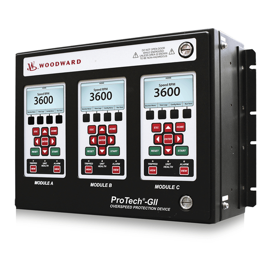
- Page 1 Product Manual 26545 Original Instructions ® ProTech - GII Overspeed Protection Device 8237-1244, -1245, -1246, -1247, 8237-1367, -1368 -1369, -1370 Installation and Operation Manual...
- Page 2 Protection of Electronic Controls, Printed Circuit Boards, and Modules. Woodward Governor Company reserves the right to update any portion of this publication at any time. Information provided by Woodward Governor Company is believed to be correct and reliable. However, no responsibility is assumed by Woodward Governor Company unless otherwise expressly undertaken.
-
Page 3: Table Of Contents
Monitor Only ......................53 Monitor and Control ....................53 Modbus Communication ..................54 Port Adjustments ....................54 ProTech-GII Parameter Addresses ..............55 5. T ............... 59 HAPTER ROUBLESHOOTING I/O Troubleshooting ....................60 Trip Indications ..................... 63 ... - Page 4 Levels of Operation of the Programming and Configuration Tool (PCT) ...107 Using the Programming and Configuration Tool (PCT)........108 On-Line Menu .....................110 Configuration of the ProTech-GII ................118 On-Line Configuration ..................119 Off-Line Configuration ..................121 Configuration Settings ..................133 ...
- Page 5 Manual 26545 ProTech-GII Overspeed Protection Device Illustrations and Tables Figure 1-1. Typical ProTech-GII Application (Voted Trip Relay Models) ....2 Figure 1-2. Typical ProTech-GII Application (Independent Trip Relay Models) ..3 Figure 1-3. Typical Gas Turbine Application (Voted Trip Relay Models) ....3 ...
- Page 6 Figure 3-12. Independent Trip Relay Response Time (Typical) Graph ....52 Figure 3-13. Voted Trip Relay Response Time (Typical) Graph ......52 Figure 8-1. ProTech-GII Front Panel ..............73 Figure 8-2. ProTech-GII Screen ................74 Figure 8-3. ProTech-GII Faceplate ............... 75 ...
- Page 7 Manual 26545 ProTech-GII Overspeed Protection Device Illustrations and Tables Table 4-1. Supported Modbus Function Codes ........... 54 Table 4-2. Boolean Write Addresses (Code 05) ..........56 Table 4-3. Boolean Read Addresses (Code 02) ..........57 Table 4-4. Analog Read Addresses (Code 04) ............ 58 ...
-
Page 8: Regulatory Compliance
ProTech-GII Overspeed Protection Device Manual 26545 Regulatory Compliance European Compliance for CE Marking Declared to 2004/108/EC COUNCIL DIRECTIVE of 15 EMC Directive: Dec 2004 on the approximation of the laws of the Member States relating to electromagnetic compatibility and all applicable amendments. - Page 9 Manual 26545 ProTech-GII Overspeed Protection Device Other International Compliance Declared to Australian Radiocommunications Act of C-Tick: 1992 and the New New Zealand Radiocommunications Act of 1989. TÜV certified for SIL-3 per IEC 61508 Parts 1-7, TÜV: Functional Safety of Electrical / Electronic /...
- Page 10 ProTe ech-GII Over rspeed Prote ection Device Manual 26545 Do not remov ve module un nless modul e is de-energ gized and all l wire connections have been d disconnected The S Service Port (R RS-232 comm munication) is s not designed d to remain c onnected during...
-
Page 11: Electrostatic Discharge Awareness
PCB from the control cabinet, place it in the antistatic protective bag. To prevent damage to electronic components caused by improper handling, read and observe the precautions in Woodward manual 82715, Guide for Handling and Protection of Electronic Controls, Printed Circuit Boards, and Modules. -
Page 12: Acronyms And Definitions
ProTech-GII Overspeed Protection Device Manual 26545 Acronyms and Definitions 2oo3 2-out-of-3 Block Identifier The identifier used for each logic block for configuration purposes (Chapter 9) Controller Area Network Diagnostic Coverage Distributed Control System Module Functionality contained within one of the three identical... -
Page 13: Chapter 1. General Information
Chapter 1. General Information Description The ProTech-GII is a device designed to safely shutdown steam, gas and hydro turbines, as well as motors, compressors, reciprocating engines and other equipment, upon sensing an overspeed or over-acceleration event. The ProTech-GII consists of three independent modules whose trip outputs are either independent or voted in a 2-out-of-3 configuration. -
Page 14: Applications
Manual 26545 Applications The ProTech-GII is designed to be applied as an overspeed device for any size steam, gas, or hydro turbine, reciprocating engine, or plant process equipment. The device's fast (12 millisecond) response time, 0.5 to 32 000 rpm speed range,... -
Page 15: Figure 1-2. Typical Protech-Gii Application (Independent Trip Relay Models)
Manual 26545 ProTech-GII Overspeed Protection Device Figure 1-2. Typical ProTech-GII Application (Independent Trip Relay Models) Figure 1-3. Typical Gas Turbine Application (Voted Trip Relay Models) Woodward... -
Page 16: Chapter 2. Installation
This chapter provides instructions on how to mount and connect the ProTech-GII into a system. Hardware dimensions, ratings, and jumper configurations are given to allow a customer to mount, wire, and configure the ProTech-GII package to a specific application. Electrical ratings, wiring requirements, and options are provided to allow a customer to fully install the ProTech-GII into a new or existing application. -
Page 17: Enclosures
Once installed within an IP56 rated panel or cabinet, the ProTech-GII panel-mounted models are rated for IP56-based environments. A gasket is attached to the rear side of the package’s bezel to properly seal the ProTech-GII control’s face-plate and around the mounting studs to a panel. With these models, field wiring access is located on the ProTech-GII control’s back side, and... -
Page 18: Figure 2-1. Typical Protech-Gii Bulkhead Package-Front View
ProTech-GII Overspeed Protection Device Manual 26545 Figure 2-1. Typical ProTech-GII Bulkhead Package—Front View Figure 2-2. Typical ProTech-GII Bulkhead Package—Front Door Open Figure 2-2a. Bulkhead Schematic Showing Front Panel A Connection to Module A and Front Panel C Connection to Module C—Top View... -
Page 19: Figure 2-3. Mounting Outline Diagram For Bulkhead-Mounted Models
Manual 26545 ProTech-GII Overspeed Protection Device Figure 2-3. Mounting Outline Diagram for Bulkhead-Mounted Models Note: The outline drawings for the TPS and GII are identical. The TPS is shown for reference. Woodward... -
Page 20: Figure 2-4A. Typical Protech-Gii Panel Mount Package-Front View
ProTech-GII Overspeed Protection Device Manual 26545 Figure 2-4a. Typical ProTech-GII Panel Mount Package—Front View Figure 2-4b. Typical ProTech-GII Panel Mount Package—Rear View with Cover Woodward... -
Page 21: Figure 2-4C. Typical Protech-Gii Panel Mount Package-Rear View Without Cover Showing Module Orientation
A is on the left and module C is on the right. Figure 2-4c. Typical ProTech-GII Panel Mount Package—Rear View without Cover Showing Module Orientation Module identification is always from left to right, with module A on the left, module B in the center, and module C on the right. -
Page 22: Figure 2-5. Mounting Outline Diagram For Panel-Mount Models
ProTech-GII Overspeed Protection Device Manual 26545 Figure 2-5. Mounting Outline Diagram for Panel-Mount Models Woodward... -
Page 23: Mounting Location Considerations
II (per IEC 60664-1) Power Supply Requirements Each ProTech-GII system consists of three separate internal modules (A, B, C), and each of these three modules accept two input power sources. Depending on the ProTech-GII model purchased, the internal modules will accept either two high voltage (HV) input power sources or one HV input power source and one low voltage (LV) input power source. - Page 24 Input #2: Low Voltage Power Supply (18–32 Vdc) @ 90 W (30 W per module) o Nominally 24 Vdc Each ProTech-GII module will function normally with power sourced to both or either power supply input independently, however Woodward recommends that both input power sources be used to improve system availability. Please refer to Table 1-1 for available ProTech-GII models.
-
Page 25: Shielded Wiring
Do not run shielded signal wires with other wires carrying large currents or high voltages. See Woodward manual 50532, EMI Control in Electronic Governing Systems, for more information. -
Page 26: Control Wiring Guidelines
EXPLOSION HAZARD—Do not connect or disconnect while circuit is live unless area is known to be non-hazardous. Figures 2-8 and 2-9 show the control wiring diagrams for the ProTech-GII system. Refer to Figure 2-10 for proper routing and stress relief of field wiring entering the ProTech-GII system. - Page 27 Manual 26545 ProTech-GII Overspeed Protection Device The ProTech-GII control’s terminal blocks are designed to be removed by hand. With circuit power & trip (interposing) relay controlled power disconnected, all terminal blocks can be removed, one at a time by unscrewing their terminal- locking screws and pulling them out of their sockets by hand.
-
Page 28: Figure 2-7. Inside View Of Protech-Gii
ProTech-GII Overspeed Protection Device Manual 26545 Figure 2-7. Inside View of ProTech-GII Woodward... -
Page 29: Figure 2-8. Protech-Gii Control Wiring Diagram
Manual 26545 ProTech-GII Overspeed Protection Device Figure 2-8. ProTech-GII Control Wiring Diagram Woodward... -
Page 30: Figure 2-9. Trip Module - Included Within Voted Trip Relay Units Only
ProTech-GII Overspeed Protection Device Manual 26545 Figure 2-9. Trip Module – Included within Voted Trip Relay Units Only Figure 2-10a. Power Supply Field Wiring Routing & Stress Relief Diagram Woodward... -
Page 31: Figure 2-10B. I/O Wiring Routing & Stress Relief Diagram
Manual 26545 ProTech-GII Overspeed Protection Device Figure 2-10b. I/O Wiring Routing & Stress Relief Diagram Figure 2-10c. Relay Output Field Wiring Routing & Stress Relief Diagram Woodward... -
Page 32: Figure 2-11A. Example Mpu (Passive Magnetic Pickup Unit) Wiring
Manual 26545 Speed Sensor Inputs To sense speed, each ProTech-GII module (A, B, C) accepts a signal from a speed sensor mounted reading off of a gear connected or coupled to the turbine’s rotor or engine’s crank shaft. Speed sensors may be any of the following: ... -
Page 33: Figure 2-11B. Example Proximity Probe (Active Magnetic Pickup Unit) Wiring (Internal Power)
Manual 26545 ProTech-GII Overspeed Protection Device +24V Active Probe Configured 24V Proximity Probe 3.3K 3.3K Active Probe Configured Figure 2-11b. Example Proximity Probe (Active Magnetic Pickup Unit) Wiring (Internal Power) Figure 2-11c. Example Proximity Probe (Active Magnetic Pickup Unit) Wiring... -
Page 34: Figure 2-12A. Example Standard Discrete Input Wiring (Internal Power Option)
Refer to Figure 2-12 for wiring information. In general, an input contact signal must change state for a minimum of 10 milliseconds for a ProTech-GII module to sense and register a change in state. The Dedicated Discrete Inputs are Start, Reset and Speed-Fail-Override. -
Page 35: Figure 2-13. Example Analog Output Wiring
Figure 2-13. Example Analog Output Wiring Relay Outputs Two basic ProTech-GII model variations are available depending on the required trip system architecture: the “Independent Trip Relay” model and the “Voted Trip Relay” model. Either version also has 3 programmable Relay Outputs per module. -
Page 36: Figure 2-14A. Example Trip Relay Output Wiring
24 Vdc @ 1 A. Two of these relay outputs are dedicated as redundant trip signal outputs, and the third is the Alarm relay. The Independent Trip Relay ProTech-GII models are designed so the each set of trip relays drive one of three external independent trip solenoids, typically used in 2-o-o-3 voted trip block assemblies. -
Page 37: Figure 2-14B. Example Trip Relay Wiring (Per Module) (Independent Trip Relay) (Internal Supply)
Note that with the “Voted Trip Relay” ProTech-GII models, the two solid-state trip relays located on each module (A, B, C) are not available for use or connection. Each module’s trip signal relays are connected internally to the ProTech-GII in a 2-o-o-3 voted fashion to drive two redundant Form-C trip relays. -
Page 38: Figure 2-14D. Example Trip Relay Wiring (Voted Trip Relay Models)
ProTech-GII Overspeed Protection Device Manual 26545 Figure 2-14d. Example Trip Relay Wiring (Voted Trip Relay Models) Woodward... -
Page 39: Figure 2-14E. Example Alarm Relay Wiring (Internal Supply)
Figure 2-14f. Example Alarm Relay Wiring (External Supply) Internal Power Supplies for Discrete Signals One internal 24 V power supply is available within each ProTech-GII module for driving external relay coils. The power supply utilizes an internal circuit shutdown to protect the power supply from over-current conditions. -
Page 40: Figure 2-15. Power Supply Relationship Diagram
ProTech-GII Overspeed Protection Device Manual 26545 If additional current capability is needed the Voter & Alarm relay connection points may be used as controlled switch contact connection points with an external power supply. An external supply may be used instead of the internal supply only for the independent trip relays or alarm relay as shown in Figure 2- 14f. -
Page 41: Figure 2-16A. Serial Port Interface Diagram-Rs-232
Figure 2-16a. Serial Port Interface Diagram—RS-232 Optional termination resistors for RS-485 communication networks are included within the ProTech-GII control’s internal circuitry, and only require terminal block wire jumper(s) for connection to a network, for applications requiring these termination resistors. Refer to Figure 2-18b for jumper connections. -
Page 42: Figure 2-17. Programming And Configuration Tool Cable/Interface Diagram
ProTech-GII Overspeed Protection Device Manual 26545 Service Port Communications One 9-pin Sub-D based service port per module (A, B, C) is available to interface with a computer for loading program settings into the ProTech and for reading stored log files from the ProTech using the Programming and Configuration Tool (PCT). -
Page 43: Chapter 3. Functionality
Product Models section of this chapter. Each of the three ProTech-GII modules A, B, and C are fully fault isolated from each other, so that faults in one module do not affect other modules. The modules do not share input or output information but each module is aware of the status of the others. - Page 44 Programming and Configuration Tool (PCT). A software-based PCT is included with each ProTech-GII that can be loaded onto a computer, and used to: ...
-
Page 45: Product Models
Pass a “module test token” between modules when performing a “Periodic Overspeed Test” routine Product Models Two basic ProTech-GII models are available depending on the required system architecture and related output signal(s). The ProTech-GII “Independent Trip Relay” models consist of three independent modules that each accept one speed input, then output two redundant trip commands. -
Page 46: Figure 3-1. Basic Functional Overview Of Independent Trip Relay Models
ProTech-GII Overspeed Protection Device Manual 26545 Figure 3-1. Basic Functional Overview of Independent Trip Relay Models Figure 3-2. Functional Diagram of Single ProTech-GII module with Independent Trip Relay Outputs Woodward... -
Page 47: Figure 3-3. Example Tmr Trip Block Assembly Interface
Manual 26545 ProTech-GII Overspeed Protection Device Figure 3-3. Example TMR Trip Block Assembly Interface Independent Trip Relay Output Specifications 2 (actuated simultaneously) Number of Channels SPST Solid-state, Normally Open Output Type Current Rating 24 V (32 V max) Voltage Rating... -
Page 48: Figure 3-4. Basic Functional Overview Of Voted Trip Relay Models
Speed Input Module 2-out- Speed Input of 3 “Form-C” Module Voted Trip Relays Relays Speed Input Module Figure 3-4. Basic Functional Overview of Voted Trip Relay Models Figure 3-5. Functional Diagram of Single ProTech-GII Module with Voted Trip Relay Outputs Woodward... -
Page 49: Figure 3-6. Simplex Trip Block Assembly
Manual 26545 ProTech-GII Overspeed Protection Device Single ProTechTPS HVAC/DC Module 24VDC or HVAC/DC Reset Start / Trip Relay Start Reset Trip Relay Logic Override Freq MPU or Prox Compare Set PT. Configurable Trip & Alarm Relay Logic Prog Relay Trip Header... - Page 50 Isolation other circuits Power Supplies Each ProTech-GII system consists of three separate internal modules (A, B, C), and each of these three modules accept two input power sources (for redundancy). Depending on the ProTech-GII model purchased, the internal modules will accept either two high-voltage (HV) input power sources or one HV input power source and one low-voltage (LV) input power source.
- Page 51 Manual 26545 ProTech-GII Overspeed Protection Device Low Voltage Input 18 – 32 Vdc Voltage Input Range 1.5 A @ 18 Vdc Current Input Max 1 A @ 32 Vdc (Note 1) 0.05 A Inrush Current Reverse Polarity Protection 3 ms, when operating on one power supply only...
-
Page 52: Inputs And Outputs
ProTech-GII Overspeed Protection Device Manual 26545 Internally Generated Limited Power Supply Relay Output Power Supply (24V_P) 24 Vdc ±10% Output Voltage 500 mA Current Limit Inputs and Outputs Speed Sensor Inputs Each module has one speed input which can be programmed to accept a passive MPU (magnetic pickup unit), or an active speed sensor (proximity probe signal or an eddy current probe signal). - Page 53 Each speed input is designed to operate from its own speed probe. Do not connect a speed probe to more than one input. This will compromise the ability of the ProTech-GII to sense open wire (passive mode only) and interfere with the minimum amplitude sensitivity and accuracy.
- Page 54 ProTech-GII. Shielded cable is required when connecting to the speed input. Dedicated Discrete Inputs Each ProTech-GII module (A, B, C) accepts three dedicated discrete inputs. The Dedicated Discrete Inputs are Start, Reset and Speed-Fail-Override. Start This contact input is used as part of the Start Logic “Speed Fail Timeout Trip”...
-
Page 55: Overspeed And Over-Acceleration Detection And Trip
No custom application program is required to be loaded for this functionality to operate normally. The ProTech-GII senses speed and then compares the sensed speed to its programmed overspeed trip setpoint to detect an overspeed condition and generate a trip command. -
Page 56: Start Logic
Peak speed and peak acceleration are tracked and logged for every overspeed and over-acceleration occurrence, the last 20 occurrences logged and can be viewed from a front panel or loaded to a computer via the ProTech-GII Programming and Configuration Tool (PCT). -
Page 57: Figure 3-9. Speed Fail Trip Diagram
Manual 26545 ProTech-GII Overspeed Protection Device Figure 3-9. Speed Fail Trip Diagram Speed Fail Timeout Trip If the “Speed Fail Timeout Trip” is Enabled, the sensed speed must exceed the Speed Fail Setpoint within the Speed Fail Timeout Time after a Start signal occurs, otherwise a Speed Fail Timeout Trip occurs. -
Page 58: Test Routines
ProTech-GII Overspeed Protection Device Manual 26545 Test Routines Each ProTech-GII module provides a variety of test routines to support common test requirements. In general, a test may not be started if any other module is tripped or in test or if the current module is tripped or in test. - Page 59 This test can only be performed from the front panel of the ProTech-GII. When the test is initiated, the frequency generator automatically starts at 100 rpm below the overspeed setpoint.
-
Page 60: Alarm And Trip Latches
In the “Voted Trip Relay” version of the ProTech-GII, at least two modules would have to be in the tripped state for the voter relay to go to its tripped state. - Page 61 Manual 26545 ProTech-GII Overspeed Protection Device A "trip" of the module refers to the action of the ProTech-GII module changing the state of its Trip output. When any of the Trip Latch inputs becomes true, the output of the trip latch is set TRUE. The red TRIPPED light is illuminated on the front panel.
-
Page 62: System Logs
Each module in the ProTech-GII logs (saves to memory) all trips, alarms, and overspeed or over-acceleration events. Peak speed and peak acceleration are also logged. The logs can be viewed from the front panel of the ProTech-GII or from the PCT tool. With PCT tool, the Configuration Error Log can also be viewed. -
Page 63: Figure 3-11. Response Time Definition
Manual 26545 ProTech-GII Overspeed Protection Device Voted Trip Relay The response time is less than 20 ms (Note 1) measured from detection of overspeed or out-of-range process to assertion of the trip relays. No operator intervention via the operator interface is required for the logic unit to perform the safety functions. -
Page 64: Figure 3-12. Independent Trip Relay Response Time (Typical) Graph
ProTech-GII Overspeed Protection Device Manual 26545 Analog Output The response time of the analog output is less than 10 ms measured from a change in speed to a change in the output current. Independent Trip Relay Response Time 25.00 20.00 15.00 Ind Trip Output 10.00 5.00... -
Page 65: Chapter 4. Modbus Communications
Boolean and analog read information, and can be configured to accept or ignore “write” commands, depending on the specific application’s requirements. This allows the ProTech-GII to be monitored but not controlled from any external device. Once a Modbus port’s “Enable Write Commands” setting is configured “No”, the respective ProTech-GII module will not accept “write”... -
Page 66: Modbus Communication
10 seconds or the sequence must be re-initiated. The ProTech-GII is designed to allow only one module to be tested at a time. Thus a module will only accept an Initiate Test command and perform the requested test if all three modules are healthy, not tripped, and not in a test mode. -
Page 67: Protech-Gii Parameter Addresses
Since Modbus can only handle integers, values that require a decimal point in the Modbus Master Device are multiplied by a scaling constant before being sent by ProTech-GII. See the Modbus list for the scaling used on each analog parameter. Boolean Writes (Code 05) Boolean Write registers are used by an external master device (plant DCS, etc.) -
Page 68: Table 4-2. Boolean Write Addresses (Code 05)
Analog Reads (Code 04) Analog Read registers are used by an external master device (plant DCS, etc.) to read the value of internal ProTech-GII module signals (hardware inputs, logic blocks, hardware outputs, etc.). An example of an analog read value would be actual speed. -
Page 69: Table 4-3. Boolean Read Addresses (Code 02)
Manual 26545 ProTech-GII Overspeed Protection Device ADDRESS DESCRIPTION 1:0001 Internal Fault Trip 1:0002 Power Up Trip 1:0003 Module Config Mismatch Trip 1:0004 Parameter Error Trip 1:0005 Over Speed Trip 1:0006 Over Accel Trip 1:0007 Open Wire Detected Trip 1:0008 Speed Lost Trip... -
Page 70: Table 4-4. Analog Read Addresses (Code 04)
ProTech-GII Overspeed Protection Device Manual 26545 ADDRESS DESCRIPTION UNITS RANGE 3:0001 Speed 0-30000 3:0002 Acceleration RPM/Sec -32768 - 32767 3:0301 Test Mode Time Remaining seconds 0-65535 3:0401 Speed Fail Time Remaining seconds 0-65535 3:0601 Temp Overspeed SetPoint 0-65535 3:0602 Simulated Speed RPM... -
Page 71: Chapter 5. Troubleshooting
For more in depth help, use the Programming and Configuration Tool provided with the ProTech-GII. The entry point for troubleshooting the ProTech-GII is the state of the three LEDs on lower part of the front panel. The Trip Log and the Alarm Log can also be viewed from the front panel. -
Page 72: I/O Troubleshooting
69 to 71. The voltage should be 24 V ±10%. Attach probe and measure again to verify that the probe is not overloading the voltage provided by the ProTech-GII. Dedicated discrete input Wiring fault, terminal block Verify wiring and terminal block not working (Start, Reset or loose. - Page 73 External supplies Check the power supplies that provide voltage to the relay output. If using the 24 V EXT available from the ProTech-GII, measure voltage between terminals 80, 81 and verify 24 V ±10%. If it is not, remove the wiring from the 24 V EXT to unload the output and measure again to verify the voltage is not being overloaded.
- Page 74 COM Port Check that there is power applied to the ProTech-GII module that the Programming and Configuration Tool is connected. Verify the correct COM port is selected when establishing communications and that Auto Detection BAUD rate is selected.
-
Page 75: Trip Indications
Manual 26545 ProTech-GII Overspeed Protection Device Trip Indications Problem or Description Possible Cause Suggested Actions Diagnostic Indication Internal Fault trip The module tripped on Various Connect the PCT and an internal fault view the Module Faults Log. This log expands the Internal Fault annunciation. - Page 76 ProTech-GII Overspeed Protection Device Manual 26545 Problem or Description Possible Cause Suggested Actions Diagnostic Indication Speed Probe Open Wire The module has Wiring fault or Check wiring continuity detected an open wire probe fault. and probe integrity. condition on the speed...
-
Page 77: Alarm Indications
Manual 26545 ProTech-GII Overspeed Protection Device Alarm Indications Problem or Description Possible Cause Suggested Actions Diagnostic Indication Internal Fault Alarm The module has an Various Connect the Programming internal fault that is and Configuration Tool and annunciated an alarm view the Trip And Alarm and not a trip. - Page 78 ProTech-GII Overspeed Protection Device Manual 26545 Problem or Description Possible Cause Suggested Actions Diagnostic Indication Periodic Overspd Test Indicates the User enabled the See manual for description automated Periodic simulated speed test or and limitations. Overspeed Test has test interval time expired been activated.
-
Page 79: Chapter 6. Safety Management
These products are certified for use in applications up to SIL3 according to IEC61508. Safe State The ProTech-GII is designed so that the safe state can be configured for either de-energize or energize to trip. De-energize to trip will place trip relays into their unpowered, normally open state. -
Page 80: Failure Rate Data
< 20 ms Versions The response time of the ProTech-GII is the time from when a signal is received at the ProTech-GII terminal blocks that is out of a range as defined by the programming (i.e. speed, analog input) to the point where the trip relays have changed state. -
Page 81: Limitations
Immunity: EN61000-6-2 Management of Functional Safety The ProTech-GII is intended for use according to the requirements of a safety lifecycle management process such as IEC61508 or IEC61511. The safety performance numbers in this chapter can be used for the evaluation of the overall safety lifecycle. -
Page 82: Competence Of Personnel
Functional Testing after Initial Installation A functional test of the ProTech-GII is required prior to use as a safety system. This should be done as part of the overall safety system installation check and should include all I/O interfaces to and from the ProTech-GII that are part of the safety system. - Page 83 6. Chassis isolation checks using resistance measurement. Measure from terminals 39, 66, 67 to a point on the ProTech-GII chassis (the grounding braid is a good place for this measurement): < 1 . Perform a lamp test from front panel Test Menu.
-
Page 84: Chapter 7. Asset Management
Wood dward recomm mends that yo our product be e sent back to o Woodward or to a Wood dward authoriz zed service fa acility after ev very five to te n years of co... -
Page 85: Chapter 8. Front Panel Interface
Front Panel Interface Introduction The front panel of the ProTech-GII allows the user to view current values for any inputs and view logs. The user can also reset a module, initiate start logic, initiate tests, and view or change configuration settings. This chapter defines the features and functions accessible through the front panel of the ProTech-GII. -
Page 86: Screen Layout
ProTech-GII Overspeed Protection Device Manual 26545 Screen Layout Each screen on the ProTech G-II modules follows a consistent layout pattern as shown in Figure 8-2. Figure 8-2. ProTech-GII Screen Screen Name – At the top of each screen is the “Screen Name” which identifies the type of data being displayed or the function being performed on that screen. -
Page 87: Keypad Functions
Manual 26545 ProTech-GII Overspeed Protection Device Keypad Functions Figure 8-3. ProTech-GII Faceplate Unless defined otherwise for a particular screen, the keys have the following functions: Navigates up one menu in the hierarchy of the selected menu tree. If modifying a value, ESC exits edit mode and restores the value without saving the changes. -
Page 88: Navigation
ProTech-GII Overspeed Protection Device Manual 26545 Navigation Selecting the Soft Keys below “Monitor Menu”, “View Logs”, “Config Menu”, and “Test Menu”, will bring up the associated menu for that category. Use the Up/Down arrows to navigate through the menu items. Select Enter to open the associated screen. -
Page 89: Passwords
Manual 26545 ProTech-GII Overspeed Protection Device Passwords The ProTechG-II utilizes two password levels, a Test Level Password and a Config Level Password. The same passwords are used by the Programming and Configuration Tool (PCT) and Front Panel. The Test Level Password is required to: ... -
Page 90: Monitor Menu
ProTech-GII Overspeed Protection Device Manual 26545 Monitor Menu From the “Monitor Menu” the user can view configuration settings, real time values, and status indications. When the “Monitor Menu” is selected from the soft keys, the following menu is shown: Figure 8-7. Monitor Menu The “Up Arrow”... -
Page 91: Figure 8-8. Monitor Summary
Parameter Error— Indicates a parameter error was detected, meaning there was a problem reading the settings out of the ProTech-GII remains in a tripped state. The configuration must be re- loaded from the PCT and a power cycle is required to clear this error. -
Page 92: Figure 8-9. Monitor Trip Latch
The following alarms are always displayed: Internal Fault Alarm—Indicates a failure internal to the ProTech-GII. Additional details on the fault cause are provided in the PCT’s Module Faults Log. -
Page 93: Figure 8-11. Monitor Dedicated Discrete Inputs
Manual 26545 ProTech-GII Overspeed Protection Device Monitor Dedicated Discrete Inputs Condition of the Start, Reset and Speed Fail Override Inputs. Start Input—Start Input Active. NOTE: This is TRUE if either the Front Panel START key or the START discrete input is active. -
Page 94: Figure 8-13. Monitor Speed Fail Timer
ProTech-GII Overspeed Protection Device Manual 26545 Monitor Speed Fail Timer Monitor speed fail timer Figure 8-13. Monitor Speed Fail Timer Timer Inactive: Timer not used or not started Timer Running: Timer started, timer remaining displayed. Timer starts when the start button is pressed or the start discrete signal occurs. -
Page 95: Figure 8-15. Monitor Modbus Status
Manual 26545 ProTech-GII Overspeed Protection Device ® Monitor Modbus Monitor Modbus status. *—Modbus is a trademark of Schneider Automation Inc. Figure 8-15. Monitor Modbus Status ® Link OK: Modbus Link OK ® Link Error: Modbus Link not operating properly Monitor/Set Date &... -
Page 96: Figure 8-17. Set Date & Time
ProTech-GII Overspeed Protection Device Manual 26545 To set the Time and Date, press the “ENTER” key. Figure 8-17. Set Date & Time The field to be edited will be highlighted. Pressing the UP/DOWN/RIGHT/LEFT arrows will highlight other fields. Press ENTER to edit the highlighted item and use the soft keys as indicated to adjust the value to the desired value. -
Page 97: Figure 8-19. Monitor System Status
Manual 26545 ProTech-GII Overspeed Protection Device Selecting ESC is the same as “Cancel” and the time and date remain at the original values. System Status Monitors the health status of all modules in the system. Figure 8-19. Monitor System Status Unknown Status: Status is unknown possibly due to a communication failure with the front panel. -
Page 98: View Logs
ProTech-GII Overspeed Protection Device Manual 26545 View Logs From the “View Logs” screens the user can view logged events with corresponding time stamps. Logged data can be viewed and exported to a file using the Programming and Configuration Tool (PCT). -
Page 99: Figure 8-22. Overspeed/Overacceleration Log
Manual 26545 ProTech-GII Overspeed Protection Device Figure 8-22. Overspeed/Overacceleration Log TEST will appear next to the time in if the module was in test mode at the time of the trip. Trip Log Log of any trip events. Displays event ID, time and date stamp, first out, and test information. -
Page 100: Figure 8-24. Alarm Log
ProTech-GII Overspeed Protection Device Manual 26545 Alarm Log Log of any alarm events Displays event ID, time and date stamp, and test information Events that occurred while a test mode was active are noted in the Test column. -
Page 101: Configure Menu
Manual 26545 ProTech-GII Overspeed Protection Device Reset Logs Allows the user to reset All Logs (Trip, Alarm, and Overspeed/Overacceleration), or just the Peak Speed/Acceleration log. Figure 8-26. Reset Logs Reset Log Procedure 1. Use the Up Down arrows to select reset “All Logs” or “Peak Speed/Acceleration”... -
Page 102: Figure 8-28. Configure Speed Input
ProTech-GII Overspeed Protection Device Manual 26545 Entering the Edit Mode from the Front Panel When a value that can be edited is highlighted, the Screen Message “Press ENTER to Edit value” appears. If the module is not Tripped and ENTER is selected the Screen Message “Module Not Tripped!”... - Page 103 Manual 26545 ProTech-GII Overspeed Protection Device Editing Values from the Front Panel Once a valid password has been entered, the parameter is highlighted. If the parameter is a value or string, a cursor indicates which digit or character is being edited.
- Page 104 ProTech-GII Overspeed Protection Device Manual 26545 Configure Speed Set values for speed, acceleration, and start logic. Configure Speed Input—Set the following parameters. Configure Acceleration—Set the following parameters. Woodward...
-
Page 105: Figure 8-29. Configure Start Logic
Manual 26545 ProTech-GII Overspeed Protection Device Configure Start Logic—Set the following parameters. Figure 8-29. Configure Start Logic Configure Trip Latch Set action of the Trip Latch (Energize or De-energize to Trip). Figure 8-30. Configure Trip Latch Configure Analog Output ... -
Page 106: Figure 8-32. Configure Test Modes
ProTech-GII Overspeed Protection Device Manual 26545 Configure Test Modes Set parameters for internal test modes. Temporary Overspeed Trip – The value that the overspeed trip setpoint will be changed to while the Temporary Overspeed Trip Test is active. Temp Overspeed Trip Timeout - How long the unit will stay in this test mode, before aborting the test (0-30 minutes). -
Page 107: Figure 8-34. Configure Modbus
Configuration Compare—User selects if this comparison feature is used or not. This feature continuously compares the configuration of the current module against the other two modules in the ProTech-GII. Copy Configuration—Allows the user to copy the configuration in the current module to one or both of the other two modules in the ProTech- GII. -
Page 108: Figure 8-36. Configuration Overview
Configuration Compare—User selects whether this comparison feature is USED or NOT USED. This routine compares the configuration of the current module against the other two modules in the ProTech-GII and generates an alarm if there is a difference. Figure 8-37. Configuration Compare... -
Page 109: Figure 8-38. Configuration Copy
Manual 26545 ProTech-GII Overspeed Protection Device Copy Configuration—Allows the user to copy the configuration in the current module to one or both of the other two modules in the ProTech- GII. Figure 8-38. Configuration Copy Configuration Copy Procedure 1. Configuration Compare must be configured to “Used” on the current module and the target module(s), for this routine to function. -
Page 110: Figure 8-39. Password Change
6. Once the new password has been selected press Enter to save it. 7. A message will appear to confirm that the password has been changed. There is no means to reset the password if it is forgotten. Units requiring a password reset must be returned to Woodward. Woodward... -
Page 111: Test Modes Menu
ProTech-GII Overspeed Protection Device Test Modes Menu The Test Modes Menu provides access to all of the ProTech-GII tests. The user can initiate any configured test the front panel. The Test or Config Level password must be entered to start any of these tests except for the Lamp Test. -
Page 112: Figure 8-41. Temporary Overspeed Test
ProTech-GII Overspeed Protection Device Manual 26545 Module Already Tripped! Test Aborted – Indicates that the test cannot be started because the module is already tripped. Test in Progress - Indicates that the test cannot be started because the module is already in the test mode. -
Page 113: Figure 8-42. Manual Simulated Speed Test
Manual 26545 ProTech-GII Overspeed Protection Device The following Messages may be seen on the Temp. Overspeed Threshold Test page: At Least One Other Module Is Tripped! – This is only used for the Temporary Overspeed Trip as a warning that another module is tripped. It does not prohibit applying this test. -
Page 114: Figure 8-43. Test Frequency Resolution
ProTech-GII Overspeed Protection Device Manual 26545 NOTE: The resolution of the internal simulated speed decreases as frequency increases. The following table indicates a few spot frequencies. In the following table and graph, it is assumed that a 60 teeth gear is used with a gear ratio of 1, making frequency the same as RPM. - Page 115 Manual 26545 ProTech-GII Overspeed Protection Device Simulated Speed Test (Auto or Manual) Procedure To configure this test, see Configure Test Modes Procedure in the section above. See Chapter 3 for a full description of this test. 1. Module cannot be tripped to run this test.
-
Page 116: Figure 8-44. Periodic Overspeed Test
ProTech-GII Overspeed Protection Device Manual 26545 Periodic Overspeed Test Displays time until the next test. Display results of last test. This test can only be configured on module A. Figure 8-44. Periodic Overspeed Test Result of Last Test can be: TEST NOT STARTED, TEST PASSED, TEST FAILED, TEST NOT COMPLETED. -
Page 117: Figure 8-45. Lamp Test
Manual 26545 ProTech-GII Overspeed Protection Device Lamp Test The Lamp Test is provided to verify front panel LED functionality. During the test, each LED is cycled off and through the provided color combinations listed below. The test can be repeated as needed. A cancel function is also available. No password is required to run the test. -
Page 118: Chapter 9. Programming And Configuration Tool
Only trained personnel should have access to these tools. A straight-through serial cable is used to allow the designated computer (with the PCT program loaded on it) to communicate with a ProTech-GII. Refer to Figure 2-18 for cable-specific information. -
Page 119: Installation Of The Pct
A communication link between PC and ProTech-GII is not required. Password is not required. The configuration file to be loaded into the ProTech-GII can be created by the Programming and Configuration Tool (PCT). Test Level: A serial communication link must be established and operational. -
Page 120: Using The Programming And Configuration Tool (Pct)
Test or Config level, the following actions must be executed: A serial interface cable must be installed between PC and one of the units of the ProTech-GII. The serial cable must be wired as shown in Figure 2-17 located in Volume 1 of the 26545 document. - Page 121 If the communication link cannot be established, the Programming and Configuration Tool (PCT) continues to attempt to establish the communication link until the Disconnect Button is pressed. After communication has been established, the ProTech-GII Programming and Configuration Tool (PCT) provides two menu options: On-Line Menu...
-
Page 122: On-Line Menu
ProTech-GII Overspeed Protection Device Manual 26545 On-Line Menu The On-Line menu provides six buttons: Edit/View Configuration View Configuration Error Log View Trip and Alarm Log View Overspeed/Acceleration Log View Module Faults Log Configuration Overview This menu is always available, however a communication link must be established before the information in the logs is available for monitoring. - Page 123 If a configuration error exists, the configuration is not saved and the following screen appears when trying to upload the settings file to the ProTech-GII. All configuration errors must be resolved before a successful upload of the settings file can be completed.
- Page 124 Data Entry Errors When editing an existing settings file, or modifying the settings currently loaded in a ProTech-GII, an error window is displayed if data entered is invalid, incomplete, or out-of-range (as shown in the example below). View Trip and Alarm Log After selecting “View Trip and Alarm Log”, a list of all recent trips and/or alarms...
- Page 125 The test mode indication contains an asterisk (*) if the ProTech-GII was in any of the test modes when the fault condition(s) occurred. The logs can be saved to an html file using the Export button.
- Page 126 ProTech-GII Overspeed Protection Device Manual 26545 View Module Faults Log It is possible to view additional details of Internal Fault Alarm and Trip conditions by selecting “View Module Faults Log”. The list contains a description containing type of fault (trip or alarm), fault originator (identify which CPU faulted: Logic, Comm or Display), fault type, fault source code address, and a time stamp of the fault.
- Page 127 Manual 26545 ProTech-GII Overspeed Protection Device Configuration Overview The Configuration Overview screen shows CRC codes associated with the overall configuration and with individual (sub-component) configurations. The CRC is a value calculated from the configuration data, so that if the data changes, the CRC will change.
- Page 128 (see Trip Relay above). This CRC does not include the user-definable input names. Event Latch 1 (Not available on ProTech-GII models): CRC codes of Event Latch 1 settings on the Event Latches page. This CRC codes does not include the user-definable input names.
- Page 129 Edit/View Configuration After selecting “Edit/View Configuration”, all parameters can be set or changed and loaded to the device while the ProTech-GII is operational. After selecting this button, the following screen is displayed: A selection can be made for the parameters to be configured on-line. The changes have the same result as off-line configuration - changed parameters are immediately operational.
-
Page 130: Configuration Of The Protech-Gii
If the unit is not in trip condition, configuration changes are inhibited. If no trip condition is present, a power-up trip condition can be generated by a power supply cycle. There are two options for changing the configuration settings in ProTech-GII: Using the ProTech-GII front panel ... -
Page 131: On-Line Configuration
A password for Config Level is required. After selecting “Edit/View Configuration”, all parameters can be set or changed and loaded to the device while the ProTech-GII is operational. For on-line configuration, the following “Home” screen buttons are available: Input Configuration: ... - Page 132 ProTech-GII Overspeed Protection Device Manual 26545 Test level was selected If test level was selected, the following pop-up window appears: Communications must be stopped and restarted using Config level. Once logged in at the Config level, configuration settings can be changed.
-
Page 133: Off-Line Configuration
If the ProTech-GII module is not in a trip condition, the following pop-up window appears: To load a configuration from a PC to a ProTech-GII, the ProTech-GII must be in a trip condition. If the unit is not in trip condition, uploading is inhibited. If no trip condition is present and the unit is configured as “De-energize to Trip”, a power-... - Page 134 Compare Settings File Differences Using the Programming and Configuration Tool (PCT) in Test Level When using the ProTech-GII Programming and Configuration Tool (PCT) in test level, the management of log files is active, and the following selections from the settings pull down menu can be used: ...
- Page 135 Select the appropriate file compatible with your ProTech software. If other Woodward applications are installed on your PC, a list of choices in addition to ProTech may appear in this list. With this new window, a new configuration file for the ProTech-GII can be created which means that: ...
- Page 136 ProTech-GII to a file on PC. With the selection “Save from Device to File”, a configuration file can be loaded from the ProTech-GII to a settings file on a PC. A new file can be created or an existing file can be modified.
- Page 137 Serial communication was already established, and test level or config level was selected If serial communication was already established, and test level or config level was selected, the transfer of the configuration file from the ProTech-GII starts immediately. The configuration file is ready to be modified by the ProTech-GII Programming and Configuration Tool (PCT).
- Page 138 Select “Config Level” in the drop down menu and enter the associated password for the selected level. After the password is entered, click on the Next button and the transfer of the configuration file from the ProTech-GII to the PC file starts immediately.
- Page 139 Edit Settings File With this selection, an existing configuration file can be modified. In order to modify the configuration in the ProTech-GII, a file must be created (see “Save from Device to File” section), then modified (instructions in this section), and then re-loaded to the ProTech-GII (see Load Settings File to Device).
- Page 140 PC, then close the Settings Editor screen. The settings files have a *.wset extension. Once the file is saved, it can be uploaded to the ProTech-GII by using drop down menu Settings followed by sub-selection “Load settings file to Device”. For configuration of all particular parameters, see “Configuration Settings”...
- Page 141 To save a settings file from the Device to a file, the Config security level is required. The Test security level is not sufficient. To load a settings file to the Device, the ProTech-GII must be in a trip condition. If the unit is not in a trip condition, uploading is inhibited.
- Page 142 4. If serial communication was already established, and test level was selected, then the transfer of the configuration file to the ProTech-GII cannot be established. For uploads, Config level is required. Test level is not sufficient. The following sub-window appears: 5.
- Page 143 9. Select “Config Level”, and enter the associated password for the selected security level. After the password is entered, the transfer of the configuration file to the ProTech-GII starts. For uploads, Config level is required. Test level is not sufficient. If no trip condition exists, transfer is inhibited. A trip condition can be established by cycling the power supply.
- Page 144 The following sub-window is displayed, which shows all differences between the files: If the configuration contents of a ProTech-GII need to be compared with the configuration contents of a file, a configuration file of the contents of the ProTech- GII must first be created by selecting “Save from Device to File”.
-
Page 145: Configuration Settings
ProTech-GII Overspeed Protection Device Configuration Settings The parameter configuration of the ProTech-GII can be modified by either on-line or off-line configuration. Once the communication link is established for on-line configuration, or the settings editor is active in off-line configuration, the... - Page 146 ProTech-GII Overspeed Protection Device Manual 26545 The following parameters can be set: Configure Speed Input Probe Type: Select speed probe type. Valid values: passive or active. Nr of Gear Teeth: Set the number of teeth on the gear that the speed sensor is mounted.
- Page 147 If the “Modbus” button is selected, the following screen is displayed: The parameters for Modbus communication can be set in the “Modbus Interface” menu. Modbus utilizes a master/slave network protocol. The ProTech-GII is always a “slave”. The following fields are available: Configure Modbus settings ...
- Page 148 ProTech-GII Overspeed Protection Device Manual 26545 Test Modes The system is equipped with several internal test routines to verify configurable logic and that parameters are working correctly. The test menu of the ProTech- GII keypad contains following tests: Temporary overspeed setpoint This is an overspeed test with adjusted test speed setpoint executed with the real hardware speed signal from the rotating machine.
- Page 149 Manual 26545 ProTech-GII Overspeed Protection Device If the “Test Modes” button is selected, the following screen is displayed: The following fields are available: Configure Test Modes settings Temporary Overspeed Trip: Overspeed setpoint setting for overspeed tests with actual turbine or equipment speed signal. Valid values: 0-32000 rpm and frequency equivalent must not exceed 32000 Hz (configuration error).
- Page 150 ProTech-GII Overspeed Protection Device Manual 26545 Other Outputs Each unit has one 4–20 mA analog output. The analog output is a 4–20 mA signal proportional with measured speed of which scaling can be adjusted using the 4 mA value and 20 mA value input fields.
-
Page 151: Protech-Gii Configuration Checks
NOTE: The configuration check is performed by the ProTech-GII after a settings file is loaded to the ProTech. The PCT must be connected to the ProTech-GII to see this log. The results are stored in volatile memory so a power cycle would clear this log. -
Page 152: Chapter 10. Service Options
A Recognized Turbine Retrofitter (RTR) is an independent company that does both steam and gas turbine control retrofits and upgrades globally, and can provide the full line of Woodward systems and components for the retrofits and overhauls, long term service contracts, emergency repairs, etc. -
Page 153: Woodward Factory Servicing Options
Flat Rate Remanufacture: Flat Rate Remanufacture is very similar to the Flat Rate Repair option with the exception that the unit will be returned to you in “like- new” condition and carry with it the full standard Woodward product warranty (Woodward Product and Service Warranty 5-01-1205). This option is applicable to mechanical products only. -
Page 154: Replacement Parts
Engineering Services Woodward offers various Engineering Services for our products. For these services, you can contact us by telephone, by email, or through the Woodward website. Technical Support ... -
Page 155: How To Contact Woodward
ProTech-GII Overspeed Protection Device How to Contact Woodward For assistance, call one of the following Woodward facilities to obtain the address and phone number of the facility nearest your location where you will be able to get information and service. - Page 156 ProTech-GII Overspeed Protection Device Manual 26545 Woodward...
-
Page 157: Appendix . Declarations & Certificates
Appendix. Declarations & Certificates... - Page 158 Email and Website—www.woodward.com Woodward has company-owned plants, subsidiaries, and branches, as well as authorized distributors and other authorized service and sales facilities throughout the world. Complete address / phone / fax / email information for all locations is available on our website.
Need help?
Do you have a question about the ProTech-GII and is the answer not in the manual?
Questions and answers