Woodward 2301A Installation And Operation Manual
Load sharing and speed control
Hide thumbs
Also See for 2301A:
- Installation and operation manual (52 pages) ,
- Quick start manual (18 pages) ,
- Installation and operation manual (40 pages)

Related Manuals for Woodward 2301A


Summary of Contents for Woodward 2301A
- Page 1 Installation and Operation Manual 2301A Load Sharing and Speed Control 9900-430, 9900-431, 9900-432, 9900-433 Manual 02303...
- Page 2 Woodward Governor Company reserves the right to update any portion of this publication at any time. Information provided by Woodward Governor Company is believed to be correct and reliable. However, no responsibility is assumed by Woodward Governor Company unless otherwise expressly undertaken.
-
Page 3: Table Of Contents
Manual 02303 2301A Load Sharing & Speed Control Contents ..........LECTROSTATIC ISCHARGE WARENESS 1. G ............1 HAPTER ENERAL NFORMATION Description......................1 Applications ......................2 2. I ................8 HAPTER NSTALLATION Unpacking.......................8 Power Requirements ....................8 Location Considerations..................8 Electrical Connections....................8 Setting Speed Range .....................9 Potential Transformer Connections................9... - Page 4 PCB from the control cabinet, place it in the antistatic protective bag. CAUTION—ELECTROSTATIC DISCHARGE To prevent damage to electronic components caused by improper handling, read and observe the precautions in Woodward manual 82715, Guide for Handling and Protection of Electronic Controls, Printed Circuit Boards, and Modules. Woodward...
-
Page 5: Chapter 1. General Information
9900-432 110 V power, forward-acting • 9900-433 110 V power, reverse-acting The 2301A control is housed in a sheet-metal chassis and consists of a single printed circuit board. All potentiometers are accessible from the front of the chassis. The 2301A provides control in either isochronous or droop mode. -
Page 6: Applications
2301A Load Sharing & Speed Control Manual 02303 Applications The 2301A electronic control has a switch-selectable speed range. The control can be set to operate within one of the following rated speed ranges: • 500 to 1 500 Hz •... -
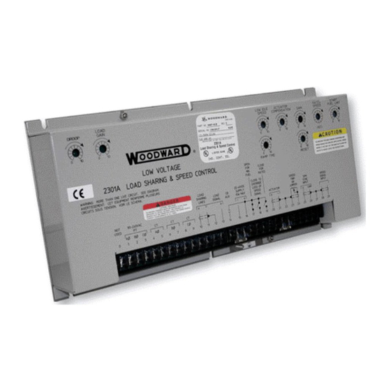
Page 7: Figure 1-1. 2301A Load Sharing And Speed Control
Manual 02303 2301A Load Sharing & Speed Control Figure 1-1. 2301A Load Sharing and Speed Control Woodward... -
Page 8: Figure 1-2. Plant Wiring Diagram (9900-430)
2301A Load Sharing & Speed Control Manual 02303 Figure 1-2. Plant Wiring Diagram (9900-430) Woodward... -
Page 9: Figure 1-3. Plant Wiring Diagram (9900-431)
Manual 02303 2301A Load Sharing & Speed Control Figure 1-3. Plant Wiring Diagram (9900-431) Woodward... -
Page 10: Figure 1-4. Plant Wiring Diagram (9900-432)
2301A Load Sharing & Speed Control Manual 02303 Figure 1-4. Plant Wiring Diagram (9900-432) Woodward... -
Page 11: Figure 1-5. Plant Wiring Diagram (9900-433)
Manual 02303 2301A Load Sharing & Speed Control Figure 1-5. Plant Wiring Diagram (9900-433) Woodward... -
Page 12: Chapter 2. Installation
If any damage is found, immediately notify the shipper. Power Requirements The high-voltage versions of the 2301A control requires a voltage source of 90 to 150 Vdc or 88 to 132 Vac 50/60 Hz for operating power. The low-voltage versions require a voltage source of 20-40 Vdc. -
Page 13: Setting Speed Range
The other end of the shields must be left open and insulated from any other conductor. Do not run shielded signal wires with other wires carrying large currents. See Woodward application note 50532, EMI Control for Electronic Governing Systems, for more information. -
Page 14: Current Transformer Connections
Use shielded cable and connect the load-sharing lines directly to terminals 10(+) and 11(–). Connect the shield to terminal 12. When all controls in the system are of the 2301A type, the shields may be connected continuously between controls. When load sharing with different controls, do not connect the shields at the point where connections are made to the load-sharing-line bus. -
Page 15: Minimum Fuel Contact
Manual 02303 2301A Load Sharing & Speed Control Minimum Fuel Contact The minimum-fuel contact (terminal 17) is intended as an optional means for a normal shutdown of the engine. It is connected in series with terminal 16 on low- voltage models OR with terminal 0 on high-voltage models (see the plant wiring diagram, Figure 1-2). -
Page 16: External Speed Trim
2301A Load Sharing & Speed Control Manual 02303 External Speed Trim A jumper must be connected to terminals 23 and 24 unless an optional remote Speed Trim potentiometer is used. If a Speed Trim pot is used, connect it as shown in the plant wiring diagram, Figure 1-2, using shielded wire. - Page 17 Manual 02303 2301A Load Sharing & Speed Control Check for Grounds Make sure power is off. Check for grounds by measuring the resistance from terminal 11 to chassis, and from terminals 15 to 11. The resistance should be infinite. If a resistance other than infinite is obtained, remove the connections from each terminal one at a time until the resistance is infinite.
-
Page 18: Chapter 3. Operation And Adjustment
2301A Load Sharing & Speed Control Manual 02303 Chapter 3. Operation and Adjustment Initial Pre-Start Settings WARNING—START-UP To prevent possible serious injury or death from engine overspeed, or damage to equipment from improper operation, carefully read and understand this entire procedure before starting the engine. -
Page 19: Adjust For Stable Operation
Manual 02303 2301A Load Sharing & Speed Control NOTE This is for initial engine start-up only. For normal start-up, the Close For Rated contact should be open if the engine is to start at idle. Apply input power to the control. - Page 20 2301A Load Sharing & Speed Control Manual 02303 If the engine is hunting at a rapid rate, slowly decrease the GAIN (turn the potentiometer counterclockwise) until performance is stable. Adjusting the GAIN may cause a momentary speed change which can be minimized by turning the GAIN potentiometer slowly.
-
Page 21: Figure 3-1. Diesel Engine Performance Curves
Manual 02303 2301A Load Sharing & Speed Control Figure 3-1. Diesel Engine Performance Curves Woodward... - Page 22 2301A Load Sharing & Speed Control Manual 02303 Actuator Compensation Adjustment If the ACTUATOR COMPENSATION is set as described under INITIAL PRE-START SETTINGS, no further adjustment is normally required. If a slow periodic instability remains, slightly increase the ACTUATOR COMPENSATION (turn the potentiometer clockwise), and repeat the GAIN and RESET adjustments.
-
Page 23: Speed Sensor Check
Manual 02303 2301A Load Sharing & Speed Control With the engine operating at rated speed and no load, record the voltage across actuator terminals 20(+) and 21(–). Shut down the engine and activate the Failed Speed Signal Override by closing the override contact. The voltage to the actuator should now be adjustable by the START FUEL LIMIT potentiometer. - Page 24 2301A Load Sharing & Speed Control Manual 02303 If the phasing is incorrect, proceed to the Phase Correction Procedure. If the phasing appears correct, skip the Phase Correction Procedure and go to the Load Gain Adjustment procedure. NOTE If after completing the LOAD GAIN and DROOP adjustments, the control loading is extremely sensitive to changes in the power factor when operating in parallel, complete the phase correction procedure.
-
Page 25: Figure 3-2. Temporary Wiring For Transformer Phase Correction
Manual 02303 2301A Load Sharing & Speed Control Figure 3-2. Temporary Wiring for Transformer Phase Correction If the temporary burden resistors described above and shown in Figure 3-2 are not used, the engine MUST be shut down in addition to removing the load in the following procedure. - Page 26 2301A Load Sharing & Speed Control Manual 02303 13. Unload the system, remove phase A CT wires from terminals 6 and 7, and connect them to phase C input terminals 8 and 9.* 14. Apply full load, measure the load signal, and record this voltage.
-
Page 27: Load Gain Adjustment
It may be necessary to reduce the load-signal voltage of each unit in the system to as low as 3 V in cases of extremely poor system dynamics. If your system requires a load-signal voltage as low as 3 V, consult Woodward for suggestions for possible remedies. -
Page 28: Figure 3-3. Droop Adjustment
2301A Load Sharing & Speed Control Manual 02303 Setting Droop For An Isolated Load Open the droop contact connected to terminal 14. Start the engine and adjust the RATED SPEED potentiometer for rated speed with no load. Apply full load and adjust the DROOP potentiometer to give the desired speed. - Page 29 Manual 02303 2301A Load Sharing & Speed Control WARNING—GENERATOR OVERLOAD To prevent possible serious injury, death, or damage to equipment from generator overload, carefully monitor load when you close the breaker. If when you close the breaker, the load on the unit increases rapidly, immediately open the breaker and shut the unit down.
-
Page 30: Chapter 4. Description Of Operation
Manual 02303 Chapter 4. Description of Operation General The 2301A controls engine speed and, during parallel operation of two or more generators, load sharing. The speed control system (shown in Figure 4-1) consists of: • A device (1) to sense the speed of the engine •... -
Page 31: Terminals For External Devices
Manual 02303 2301A Load Sharing & Speed Control A failed-speed-signal circuit monitors the speed-signal input. When no signal is detected in the forward-acting type of control, the circuit calls for minimum fuel. The minimum-fuel signal is sufficient to cause the actuator to go to the minimum position if not restricted. -
Page 32: Paralleling
2301A Load Sharing & Speed Control Manual 02303 Figure 4-2. Terminal Connections Paralleling There are two basic methods used for paralleling: droop, where speed decreases with load, and isochronous, where speed remains constant. The paralleling system as shown in Figure 4-3 consists of: •... -
Page 33: Figure 4-3. Paralleling System
DROOP potentiometer (shown in Figure 1-1). The 2301A Load Sharing and Speed Control is powered by a dc-dc isolated power supply, which allows operation over a wide voltage range without generating excessive heat. -
Page 34: Chapter 5. Troubleshooting
2301A Load Sharing & Speed Control Manual 02303 Chapter 5. Troubleshooting The following troubleshooting guide is an aid in isolating trouble to the control box, actuator, plant wiring, or elsewhere. Troubleshooting beyond this level is recommended ONLY when a complete facility for control testing is available. - Page 35 Manual 02303 2301A Load Sharing & Speed Control Table 5-1. Troubleshooting Problem Cause Remedy Engine will not start. Supply voltage polarity reversed Check for supply voltage from terminals 16(+) to Actuator not moving to (dc only), or no supply voltage.
- Page 36 (T20 and T21) until the speed setting is completely counterclockwise (or does not reduce fuel at any position), the 2301A control may be faulty, or may have the wrong speed range. If the voltage is cut back, look for a problem in the linkage or actuator.
- Page 37 Check the magnetic pickup output voltage at control. speeds above idle—at least 1.0 Vrms. If magnetic pickup should fail and the speed-signal-override- failed circuit is disabled, the 2301A control will call for maximum fuel. 2301A control amplifier. Control the engine manually at rated speed and adjust the Rated Speed setting fully counterclockwise.
- Page 38 External wiring may require additional shielding or rerouting from high-current lines or components. If the problem cannot be solved by these checks, it will be necessary to remove the 2301A control from the switchgear. Temporarily mount the control next to the engine and connect only a...
- Page 39 Manual 02303 2301A Load Sharing & Speed Control Problem Cause Remedy Engine will not stabilize Necessary external wires not If stability occurs when the control is mounted next at rated no-load speed. properly shielded. (Electrical to the engine, return the control to the switchgear.
-
Page 40: Chapter 6. Service Options
Product Service Options The following factory options are available for servicing Woodward equipment, based on the standard Woodward Product and Service Warranty (5-01-1205) that is in effect at the time the product is purchased from Woodward or the service is performed: •... -
Page 41: Returning Equipment For Repair
Returning Equipment for Repair If a control (or any part of an electronic control) is to be returned to Woodward for repair, please contact Woodward in advance to obtain a Return Authorization Number. When shipping the item(s), attach a tag with the following information: •... -
Page 42: Replacement Parts
To expedite the repair process, contact Woodward in advance to obtain a Return Authorization Number, and arrange for issue of a purchase order for the item(s) to be repaired. No work can be started until a purchase order is received. -
Page 43: Engineering Services
2301A Load Sharing & Speed Control Engineering Services Woodward Industrial Controls Engineering Services offers the following after- sales support for Woodward products. For these services, you can contact us by telephone, by email, or through the Woodward website. • Technical Support •... -
Page 44: Technical Assistance
Type of Fuel (gas, gaseous, steam, etc) Rating Application Control/Governor Information Please list all Woodward governors, actuators, and electronic controls in your system: Woodward Part Number and Revision Letter Control Description or Governor Type Serial Number Woodward Part Number and Revision Letter... - Page 45 Manual 02303 2301A Load Sharing & Speed Control Woodward...
-
Page 47: 2301A Control Specifications
2301A Control Specifications Part Numbers: 9900-430 24 V, forward-acting 9900-431 24 V, reverse-acting 9900-432 110 V, forward-acting 9900-433 110 V, reverse-acting Speed Ranges (switch selectable): Range 1 500-1500 Hz Range 2 1000-3000 Hz Range 3 (factory setting) 2000-6000 Hz Range 4... - Page 48 Phone +1 (970) 482-5811 • Fax +1 (970) 498-3058 Email and Website—www.woodward.com Woodward has company-owned plants, subsidiaries, and branches, as well as authorized distributors and other authorized service and sales facilities throughout the world. Complete address / phone / fax / email information for all locations is available on our website.
Need help?
Do you have a question about the 2301A and is the answer not in the manual?
Questions and answers