Woodward 723PLUS Installation And Operation Manual
Digital marine control
Hide thumbs
Also See for 723PLUS:
- Installation and operation manual (176 pages) ,
- Original instructions manual (168 pages) ,
- Technical manual (120 pages)

Related Manuals for Woodward 723PLUS


Summary of Contents for Woodward 723PLUS
- Page 1 Product Manual 02881 (Revision D, 7/2008) Original Instructions 723PLUS Digital Marine Control Two-engine Mechanical Load Sharing 8280-422, 8280-423 Installation and Operation Manual...
- Page 2 Revisions—Changes in this publication since the last revision are indicated by a black line alongside the text. Woodward reserves the right to update any portion of this publication at any time. Information provided by Woodward is believed to be correct and reliable. However, no responsibility is assumed by Woodward unless otherwise expressly undertaken.
-
Page 3: Table Of Contents
............1 HAPTER ENERAL NFORMATION Introduction ......................1 Application ......................1 723PLUS Control Accessories ................2 2. I/O O ................ 9 HAPTER PERATION Introduction ......................9 Analog Output #1 (Terminal Block #15 and #16) ........... 9 ... - Page 4 Contacting Woodward’s Support Organization ............ 96 Technical Assistance .................... 97 723PLUS C ............98 ONTROL PECIFICATIONS The following are trademarks of Woodward, Inc.: DSLC Woodward The following are trademarks of their respective companies: Modbus (Schneider Automation Inc.) Woodward...
- Page 5 Manual 02881 723PLUS Digital Marine Control Illustrations and Tables Figure 1-1. 723PLUS Marine Load Sharing System ..........3 Figure 1-2a. Functional Block Diagram ..............4 Figure 1-2b. Functional Block Diagram ..............5 Figure 1-3a. Control Wiring Diagram ..............6 ...
-
Page 6: Warnings And Notices
Start-up On- and off-highway Mobile Applications: Unless Woodward's control functions as the supervisory control, customer should install a system totally independent of the prime mover control system that... -
Page 7: Electrostatic Discharge Awareness
Do not touch the components or conductors on a printed circuit board with your hands or with conductive devices. To prevent damage to electronic components caused by improper handling, read and observe the precautions in Woodward manual 82715 , Guide for Handling and Protection of Electronic Controls, Printed Circuit Boards, and Modules. - Page 8 723PLUS Digital Marine Control Manual 02881 Woodward...
-
Page 9: Chapter 1. General Information
Chapter 1. General Information Introduction This manual describes the Woodward 723PLUS Digital Marine Speed Controls, 8280-422 (low-speed engines, typically less than 100 rpm) and 8280-423 (medium-/high-speed engines, over 100 rpm). These controls are intended to be used where mechanical load sharing and unit clutching is required. -
Page 10: 723Plus Control Accessories
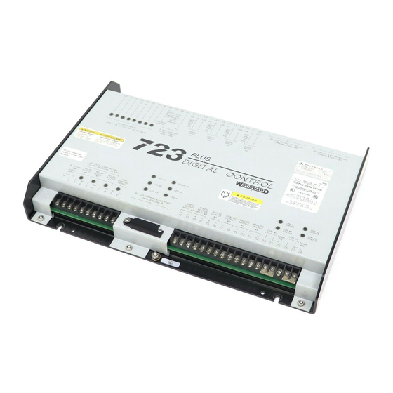
723PLUS control’s operation. See Chapter 3, Function Operation, for more details. The 723PLUS control consists of a single printed circuit board in a sheet metal chassis. Connections are via three terminal strips and three 9-pin subminiature D connectors. -
Page 11: Figure 1-1. 723Plus Marine Load Sharing System
Manual 02881 723PLUS Digital Marine Control Figure 1-1. 723PLUS Marine Load Sharing System Woodward... -
Page 12: Figure 1-2A. Functional Block Diagram
723PLUS Digital Marine Control Manual 02881 Figure 1-2a. Functional Block Diagram Woodward... -
Page 13: Figure 1-2B. Functional Block Diagram
Manual 02881 723PLUS Digital Marine Control Figure 1-2b. Functional Block Diagram Woodward... -
Page 14: Figure 1-3A. Control Wiring Diagram
723PLUS Digital Marine Control Manual 02881 Figure 1-3a. Control Wiring Diagram Woodward... -
Page 15: Figure 1-3B. Control Wiring Diagram
Manual 02881 723PLUS Digital Marine Control Figure 1-3b. Control Wiring Diagram Woodward... - Page 16 723PLUS Digital Marine Control Manual 02881 Figure 1-4. System Wiring Overview Woodward...
-
Page 17: Chapter 2. I/O Operation
This chapter contains the general input and output (I/O) description for the 723PLUS controls, 8280-422/-423. The 723PLUS control hardware is intended to be a generic control platform suitable for a wide range of applications. Each application is custom programmed including the I/O function, range, and calibration. The I/O hardware is fixed, and the wiring specifications for each 723PLUS control remain the same;... -
Page 18: Engine Speed Signal Input (Speed Sensor Input #1, #2-Tb11, Tb12, Tb13, Tb14)
(7.5–1000 Hz). The inputs are determined by the hardware configuration (jumper configuration). See the hardware manual (02877) for more information. The maximum engine speed the 723PLUS control can control is 2200 rpm. There are three different speed sensing modes: single input speed sensing, redundant speed sensing, and torsional filtering of flexible couplings speed sensing. - Page 19 Manual 02881 723PLUS Digital Marine Control Discrete Input B—Rated Speed: When 24 Vdc is applied to terminal 30, the engine can be operated at a speed higher than idle. When +24 Vdc is removed from terminal 30, the engines speed immediately begins to decelerate to idle at the idle ramp time.
-
Page 20: Fuel Rack Position Feedback (Analog Input #1-Tb42-Tb43)
Discrete Input H—Clutch Engaged: This contact in is used to tell the control the clutch status. When 24 Vdc is applied to terminal 36, the 723PLUS assumes that its clutch is engaged (closed). If 24 Vdc is absent from terminal 36, the 723PLUS assumes that the clutch is disengaged (open). -
Page 21: Manifold Air Or External Fuel Limit Input (Analog Input #3-Tb48-Tb49)
±5 Volt Aux Input (Analog Input #4—TB51– TB52) This input was made for the rare occasion that a system might also have a DSLC control. This input is scaled to work with the Woodward DSLC. Minor Alarm Contact Output (Relay Output #1—TB3,... -
Page 22: Major Alarm Contact Output (Relay Output #2-Tb5, Tb6)
Auto Mode The 723PLUS control issues a clutch closure permissive (if the necessary conditions have been met) by closing this set of contacts. There are two cases to be considered for automatic clutching. One is that no units are clutched in, and the second is that one unit is already clutched in. -
Page 23: Power Supply Input (Tb1, Tb2)
Power Supply Input (TB1, TB2) These are low voltage 723PLUS controls. 18–40 Vdc must be connected to terminals 1 (+) and 2 (–). The 723PLUS control requires about 40 W. The power supply is reverse-voltage protected. The power supply output must be low impedance (for example, directly from batteries). -
Page 24: Failed Spd Sensor #1 And #2 Leds
Troubleshooting, for more speed sensing fault details. ALARM #1 LED The ALARM #1 LED is programmed to light if both 723PLUS controls on a common gear box were programmed to be either the port or starboard control. To select which control is either the port or starboard control, go to Configure mode, under the header CONFIG SPD CONTROL, at prompt PORT ENGINE. -
Page 25: Chapter 3. Function Operation
Maximum Fuel Limiting Speed Control The primary job of the 723PLUS control is to control the engine speed. The control compares the engine speed to the speed reference and then adjusts the actuator output to maintain a zero error between engine speed and the speed reference. -
Page 26: Figure 3-1. Speed Sensor Roll-Off Filter
723PLUS Digital Marine Control Manual 02881 Figure 3-1. Speed Sensor Roll-off Filter Notch Filter To use the notch filter, make sure that the speed sensor(s) used are only on the engine side of the flexible coupling. The notch filter is a bandstop filter. It rejects specific frequencies and allows all others to pass. -
Page 27: Figure 3-2. Notch Filter
Manual 02881 723PLUS Digital Marine Control Figure 3-2. Notch Filter More Speed Sensing If both speed sensing inputs are used, the speed sensing mode will be either redundant speed sensing or torsional filtering depending on the status of the ENBLE TORSIONAL FLT. ENBLE TORSIONAL FLT is found in Configure mode, under the header CONFIG SPD CONTROL, at prompt ENBLE TORSIONAL FLT. - Page 28 MPU in one complete engine revolution. This gear must rotate at the same speed as the gear used for speed sensor #1. The number of gear teeth is used by the 723PLUS control to convert the pulses from the speed sensing device to engine rpm. To prevent...
- Page 29 Service mode, under the header *SPEED REFERENCE*, at prompt RAISE SPEED LIMIT. In case of a Remote Speed Input failure, the 723PLUS control is configurable to respond in one of two ways: go to absolute lower limit or Lock-in-Last. This selection is made in Configure mode, under the header CONFIG SPD CONTROL, at prompt LockOnLost REM SPD?.
-
Page 30: Figure 3-3. Speed Reference
Service mode, under the header *SPEED REFERENCE*, at prompt LOWER SPEED LIMIT. If the 723PLUS control is the second unit clutched-in (as Slave), all of its internal speed reference ramps will be ignored and the unit will follow the speed reference ramps as used in the Master. - Page 31 Manual 02881 723PLUS Digital Marine Control Dynamics Dynamic adjustments are the settings that affect the stability and transient performance of the engine. There are two sets of dynamics. The settings for Dynamics 1, are found in Service mode, under the header *DYNAMICS 1*. The settings for Dynamics 2, are found in Service mode, under the header *DYNAMICS 2*.
-
Page 32: Figure 3-4. Gain Slope
723PLUS Digital Marine Control Manual 02881 Figure 3-4. Gain Slope Figure 3-5. Gain Window Woodward... -
Page 33: Figure 3-6. Typical Transient Response Curves
Manual 02881 723PLUS Digital Marine Control Figure 3-6. Typical Transient Response Curves Woodward... -
Page 34: Fuel Limiting
Woodward actuator voltage will be between 0–7 Vdc. Fuel Limiting The second primary function of the 723PLUS control is to provide fuel rack limiting to protect the engine. All the fuel limiters and the PID output are connected to the actuator LSS (low-signal select) bus. The lowest input to the LSS bus is the input that is “In Control”... - Page 35 Manual 02881 723PLUS Digital Marine Control Transient Overfuel Transient Overfuel is a function that works in conjunction with the Manifold Air Pressure fuel limiter and the Torque Fuel Limiter. When either one or both of these fuel limiters are enabled, the *TRANSIENT OVR FUEL* Service header will automatically appear in the hand held programmer.
-
Page 36: Load Sharing
The maximum fuel limit is an absolute actuator driver output limit and is active at all times. This is the maximum actuator driver output the 723PLUS control will allow under any conditions, and can be used to set the engine horsepower rating. - Page 37 PERCENT LOAD. The voltage signal is proportional to the total load on both units. The 723PLUS control is capable of biasing the load sharing lines as well as reading the voltage signal on the load sharing lines. An internal relay isolates the 723PLUS control from the load sharing lines until the unit is ready to begin load sharing.
-
Page 38: Chapter 4. Service And Configure Menus
BKSP and SPACE keys will scroll through the display to show the remainder of a prompt if it is longer than the display screen's 19 characters. The 723PLUS has two sets of menus; the Service menus and Configure menus. The Service menus allow easy access and tuning while the engine is running. - Page 39 Manual 02881 723PLUS Digital Marine Control Service Menus To access the Service menus press the “Arrow Down” key from the master screen. To move between menus, and to move through set points within menus, follow the instructions as for the Configure menus. Also to return to the menu header, or to leave Service, follow the Configure instructions.
- Page 40 + (plus) Decreases set point values by one step at a time. (solid square) Not used. Displays the 723PLUS control part number and software revision level. To return to menu header or to main screen. SAVE Saves entered values (set points).
-
Page 41: Figure 4-1. Hand Held Programmer Functions
Figure 4-1. Hand Held Programmer Functions Any values that are adjusted or tuned must be saved prior to removing power to the 723PLUS control, otherwise they will revert back to their original settings. Saving is done by pressing the SAVE key on the hand held programmer. -
Page 42: Figure 4-2. Service And Configure Headers
When the hand held programmer is not being used for extended periods, it is recommended that it be disconnected from the 723PLUS control. The hand held programmer may provide an easier path for radio and other EMI signals to enter the 723PLUS control and cause undesirable conditions. -
Page 43: Configure Menus
When accessing the configuration menus the 723PLUS control will activate an I/O lock on the hardware. All outputs will be turned off (zero current/volts, extinguished LEDs) or de-energized (open contacts). - Page 44 If set to “FALSE”, the speed reference will stay at its present value when the engine is shut down. POWER UP TO IDLE (*T/F)—If set to “TRUE”, every time the 723PLUS control power is turned on, the speed reference will reset to idle even though the rated contact is closed.
-
Page 45: Figure 4-4. Dynamics Maps
Set this value “TRUE” for the 723PLUS control that is on the port engine of the two engines on common gear box. The companion unit must have an opposite value. - Page 46 MINOR ALARM TRIPS Enabling any one or a combination of the following alarms is acceptable as they are linked together as logical “ORs”. This is relay output #1, 723PLUS control terminals #3 and #4. MPU 1 FAILED (*T/F)—Set this value “FALSE” if failure of MPU 1 input is not to be a minor alarm.
- Page 47 Manual 02881 723PLUS Digital Marine Control RACK INPUT FAILED (*T/F)—Set this value “FALSE” if failure of Rack Position Feedback input is not to be a minor alarm. Set this value “TRUE” if failure of Rack Position Feedback input is to be alarmed as a minor alarm.
- Page 48 MAJOR ALARM TRIPS Enabling any one or a combination of the following alarms is acceptable as they are linked together as logical “ORs”. This is relay output #2, 723PLUS control terminals #5 and #6. MPU 1 FAILED (*T/F)—Set this value “FALSE” if failure of MPU 1 input is not to be a major alarm.
- Page 49 Manual 02881 723PLUS Digital Marine Control PORT 2&3 LINK ERROR (*T/F)—Set this value “FALSE” if no major alarm output is desired when both Port2 and Port3 detect link or hardware errors. Set this value “TRUE” if a major alarm output is desired when Port2 and Port3 detect a link or hardware error.
-
Page 50: Service Menus
723PLUS Digital Marine Control Manual 02881 HIGH ACT ALM LEVEL (%) (*0.0–100.0)—The units for this value are percent of the actuator driver output. Set this value for the desired level that the PID output must be above before the HIGH ACT ALARM is tripped. - Page 51 Level alarm has not been detected. HIGH SPEED SW (T/F)—A “TRUE” displayed indicates that the engine speed has exceeded the 723PLUS Engine Overspeed Trip point. A “FALSE” displayed indicates that the engine speed has not exceeded the 723PLUS Engine Overspeed Trip point.
- Page 52 723PLUS Digital Marine Control Manual 02881 *MINOR ALARMS* For any of the minor alarms to be displayed, they must first be enabled while in Configure mode under header MINOR ALARMS. Once the desired minor alarms are enabled in Configure mode, any one or a combination of the enabled alarms may activate the Minor Alarm output (terminals #3 and #4).
- Page 53 Level alarm has not been detected. HIGH SPEED SW (T/F)—A “TRUE” displayed indicates that the engine speed has exceeded the 723PLUS Engine Overspeed Trip point. A “FALSE” displayed indicates that the engine speed has not exceeded the 723PLUS Engine Overspeed Trip point.
- Page 54 723PLUS Digital Marine Control Manual 02881 *DYNAMICS 2* These settings are used only when dynamics 2 is selected. GAIN 2 (*0.01–150.0)—The gain is set to provide stable control of the engine at the light unloaded conditions. RESET 2 (*0.01–50.0 sec)—Reset compensates for the lag time of the engine. It adjusts the time required for the control to return the speed to zero error after a disturbance.
- Page 55 Manual 02881 723PLUS Digital Marine Control DECEL RAMP (SEC) (*0.0001–500.0 sec)—Decel Ramp is the time required for the control to ramp the engine speed from rated speed to idle speed. The ramp is started whenever the Idle/Rated contact is opened.
- Page 56 723PLUS Digital Marine Control Manual 02881 *DISCRETE IN* For all discrete inputs, a “TRUE” value indicates the contact input is closed and a “FALSE” indicates the contact input is open. STOP CONTACT (T/F)—Shows the status of the Stop contact (terminal 29).
- Page 57 Manual 02881 723PLUS Digital Marine Control TORQ LMT AT BKPT 3 (*0.0–101.0%)—This value is the torque fuel limit in percent actuator output for point 3. TORQ LIMIT BKPT 4 (*0.0–2200.0 rpm)—This value is the torque fuel limit speed input for point 4.
- Page 58 *RESPONSE TESTING* Response Testing is used for initial dynamic setup of the 723PLUS governor. ACT BUMP DURATION (*0.1–2.0 sec)—This is the time (in seconds) that the Actuator Bump will last once initiated.
- Page 59 Manual 02881 723PLUS Digital Marine Control NOTCH Q FACTOR (*0.707–25.0)—This is the width about the NOTCH FREQUENCY that the filter rejects, and is dimensionless. At the minimum value 0.707, there is no attenuation of signal gain at the resonant frequency, and the filter gain equals one.
- Page 60 723PLUS Digital Marine Control Manual 02881 AOUT1 1 SELECTION (*1–6)—Selects which item will be output to analog output #1 (terminals #15 and #16). AOUT1 FILTER (Hz) (*0.1–20.0)—This value provides an adjustable lag time in the output. ANALOG OUTPUT #1 MIN (*–30 000.0–30 000.0)—This is the value when Output #1 is 4 mA.
- Page 61 ACT SHUTDOWN (T/F)—A “TRUE” displayed indicates that the 723PLUS is asking the actuator driver output to go to the minimum fuel point. A “FALSE” displayed indicates that the 723PLUS is not asking the actuator driver output to go to the minimum fuel point.
- Page 62 (something else has control). ENGINE OVER SPED? (T/F)—A “TRUE” displayed indicates that the engine has hit the 723PLUS control overspeed trip point. This will be automatically reset each time the engine speed reaches 5% of rated speed during a start, or it can be reset by the software reset found in Service mode, at either headers “MINOR...
-
Page 63: Menu Default Values
Manual 02881 723PLUS Digital Marine Control REMOTE SPD REF (RPM) (0–2000 rpm)—This is the Remote Speed Setting value from Analog Input #2. RACK INPUT (mA)—This is the rack position sensor 4–20 mA input (Analog Input #1) signal value, displayed in milliamps. - Page 64 723PLUS Digital Marine Control Manual 02881 ENABLE AUX INPUT #FALSE CT F AS OVRSPD TEST #FALSE MANUAL CLUTCH LOGIC #FALSE USE CONT E AS RESET #FALSE USE DSLC AS SYNC #TRUE MAJOR ALM SD ACT #FALSE USE NOTCH FILTER #FALSE...
- Page 65 Manual 02881 723PLUS Digital Marine Control Menu Item Default (Low, High) As Left Port As Left Starboard *MAJOR ALARMS* MAJOR ALARM MPU 1 FAILED MPU 2 FAILED MANIFOLD AIR FAILED REMOTE SPEED FAILED RACK INPUT FAILED SPEED SWITCH ON TORQUE LIMITER...
- Page 66 723PLUS Digital Marine Control Manual 02881 DYN 2 SPD SW PU *500.0 (100.0, 2200.0) DYN 2 SPD SW DO *400.0 (1.0, 2200.0) *SPEED REFERENCE* RAISE SPEED LIMIT *900 (100, 2200) LOWER SPEED LIMIT *300 (100, 2200) IDLE SPEED (RPM) *350 (100, 2200) ACCEL RAMP (SEC) *4.0 (0.0001, 500.0)
- Page 67 Manual 02881 723PLUS Digital Marine Control FUEL LMT AT BKPT 5 *101.0 (0.0, 101.0) FUEL LIMIT BKPT 6 *20.0 (0.0, 20.0) FUEL LMT AT BKPT 6 *101.0 (0.0, 101.0) *TRANSIENT OVR FUEL* OVER FUEL TIME *0.0 (0.0, 10.0) OVER FUEL BUS UNITS *0.0 (0.0, 100.0)
- Page 68 723PLUS Digital Marine Control Manual 02881 SPEED CONTROL MODE ON MAX FUEL LIMIT ON START FUEL LIMIT BOOST LIMIT MODE TORQUE LIMIT MODE ENGINE OVER SPED? PORT 2 LINK ERROR PORT 3 LINK ERROR USE MASTER SPD REF RESET ALL ALARMS...
-
Page 69: Chapter 5. Installation And Calibration
1–5 Vdc input. Then 1 Vdc can be used in place of 4 mA, and 5 Vdc can be used in place of 20 mA. If the 723PLUS control response or the hand held readout do not agree with the information listed, stop and correct the problem before continuing with the next step. -
Page 70: Power Requirements
723PLUS Digital Marine Control Manual 02881 Power Requirements The low-voltage versions of the 723PLUS Marine Load Sharing Control requires a voltage source of 18 to 40 Vdc. To prevent damage to the control, do not exceed the input voltage range. -
Page 71: Figure 5-1. 723Plus Control Internal Jumpers
Manual 02881 723PLUS Digital Marine Control Figure 5-1. 723PLUS Control Internal Jumpers Woodward... -
Page 72: Electrical Connections
723PLUS Digital Marine Control Manual 02881 The following jumper options are available for these 723PLUS controls: JPR10 analog output #1 0–1 mA JPR9 analog output #1 0–20 mA JPR12 analog output #2 0–1 mA JPR11 analog output #2 0–20 mA JPR13 &... -
Page 73: I/O Verification
723PLUS Digital Marine Control I/O Verification Apply 18–40 Vdc power supply [TB1 (+) and TB2 (–)] to the 723PLUS control. After approximately 20 seconds, the green CPU LED should illuminate. Once the CPU LED is illuminated, plug the hand held programmer into J1. The hand held programmer will be used during the I/O verification and calibration. - Page 74 723PLUS Digital Marine Control Manual 02881 Contact F—Overspeed/Emergency Declutch Switch (Discrete Input F) Place the Contact F switch in the ON position (closed). The prompt CONTACT F, under the header *DISCRETE IN*, should read “TRUE”. Place the Contact F switch in the OFF position (open). The CONTACT F prompt should read “FALSE”.
- Page 75 723PLUS control was in run mode. ALARM #1 LED This LED is a visual indication that two 723PLUS controls on a common gear box (companion controls) were both programmed as either PORT or STARBOARD engine control.
- Page 76 Speed Sensor 2 is an optional input. Verify the MPU shield is tied only to the 723PLUS control ground and nowhere else in the system. If an MPU is used for the speed sensor, measure the resistance across terminals 13 & 14. The resistance depends on the MPU used, but should be less than 250 .
- Page 77 PRESS (mA) reading and current meter track each other throughout the range. Remove the current meter and return the wiring to its original state. Verify shield wire is connected only to the 723PLUS control and nowhere else in the system. ±5 Vdc Auxiliary Input (Analog Input #4) The ±5 Vdc Auxiliary input is programmed to be used with the Woodward DSLC...
-
Page 78: I/O Calibration
See Chapter 4 for menu item definitions. Upon completion of adjusting all configuration menu items, save the settings by pressing the SAVE button on the hand held programmer. Exit the configuration headers. The 723PLUS control will reboot before returning to normal operation. Reboot takes about 20 to 30 seconds. - Page 79 Manual 02881 723PLUS Digital Marine Control Load Sharing Lines No calibration available. Analog Output #1 Analog output #1 is configurable to output one of six different selections. This selection is made in Service mode, under header *CALIBRATION* at the prompt AOUT 1 SELECTION.
-
Page 80: Figure 5-2. Analog Output Calibration Example
723PLUS Digital Marine Control Manual 02881 Figure 5-2. Analog Output Calibration Example The prompts ANALOG OUTPUT #2 MIN and ANALOG OUTPUT #2 MAX do not display the engineering units of the value being displayed, so you will have to remember which selection was made while at the AOUT 2 SELECTION prompt. - Page 81 No calibration needed. Rack Position Input (Analog Input #1) The Rack Position Input is optional. If it is not used or fails, the 723PLUS control will default to using the actuator driver output to indicate engine load. Since the percent actuator driver signal is used for the default condition, it must always be calibrated.
- Page 82 Verify with a milliamp meter that the remote speed setting device outputs 4 mA at the minimum position to the 723PLUS and 20 mA to the 723PLUS at the maximum position. With the hand held programmer, go in Service mode, go to the header *DISPLAY 1*, and at prompt REMOTE SPEED REF, view the remote speed setting input (it is displayed in rpm).
- Page 83 Manual 02881 723PLUS Digital Marine Control The remote speed input is intended to be used with only one speed setting device, typically the bridge controller. However, some applications may require two or more speed devices be used. Due to the differences in the output signal from the multiple speed setting devices, the remote speed setting input calibration may have to be compromised to achieve acceptable results.
-
Page 84: Figure 5-3. External Fuel Limit Calibration And Scaling
723PLUS Digital Marine Control Manual 02881 Figure 5-3. External Fuel Limit Calibration and Scaling J2 and J3 All values are preset. No calibration needed. Torque Fuel Limit Adjustment The torque fuel limit is optional and, if it is not enabled, its header will not appear in Service mode. -
Page 85: Figure 5-4. Torque Fuel Limit Curve
Manual 02881 723PLUS Digital Marine Control Figure 5-4. Torque Fuel Limit Curve Start Fuel Limit Calibration The start fuel limit is set to provide the desired maximum percent actuator driver output during starts. The start fuel limit should be set to provide consistent starting during hot and cold starts. -
Page 86: Engine Start-Up
Manual 02881 Engine Start-up The 723PLUS control pre-calibration is now complete and the engine is ready to be started. The first attempt to start the engine should be done with the fuel shut off to prevent the engine from starting. This will allow the 723PLUS control, actuator, and actuator wiring to be checked prior to actually running the engine. - Page 87 Manual 02881 723PLUS Digital Marine Control Dynamics Adjustments The objective of the dynamic adjustments is to obtain the optimum, stable engine speed response from minimum speed and load to full speed and load. All adjustments apply to both sets of standard dynamics (*DYNAMICS 1* or *DYNAMICS 2*).
-
Page 88: Figure 5-6. Gain Slope
723PLUS Digital Marine Control Manual 02881 Full Load Adjustment Do these adjustments at the speed and load at which the engine is most often operated. If operation in this range is satisfactory, no further dynamic adjustments are necessary. If during changes in speed or load, excessive speed errors occur, increase the Gain Slope adjustment until engine performance is satisfactory. - Page 89 1) The load sharing relay LED must be illuminated (this indicates that the load sharing relay is closed). 2) Verify whether the 723PLUS control is using actual fuel rack position or the default fuel rack mode for engine load value.
-
Page 90: Conclusion
First, the slave will match speed with the master. When the slave unit’s speed is within ±20 rpm of the Master’s speed for 2 seconds, the slave 723PLUS control will issue a clutch permissive (Relay Output #3). Once the slave clutch has closed, the slave unit will load, and the master unit will unload at the slave’s... -
Page 91: Chapter 6. Troubleshooting
See the description of operation in Chapter 3 for the different selections. Both Speed Sensors Failed Both speed sensors faulted at the same time will cause the 723PLUS to go to the minimum fuel position. The speed sensor faults are latching faults (latching means the fault/alarm condition remains in effect even if the problem disappears, until the control is reset—see Alarm/Fault Resets below). -
Page 92: Power Supply Ok Led
MPU gap, poor MPU location, or by dirt, oil, or metal filings on the end of the probe. ALARM #1 LED The Alarm #1 LED is used to indicate if both 723PLUS controls are configured to be the same unit (both Port or both Starboard). Woodward... -
Page 93: Alarm #2 Led
If the Rack Position Input is used, we recommend that the Rack Position Fault be configured to activate one of the alarms. When the rack position fault is latched, the 723PLUS control automatically switches to the default rack calibration based on the percent actuator driver output. -
Page 94: Manifold Air Pressure Input Fault
723PLUS Digital Marine Control Manual 02881 Manifold Air Pressure Input Fault The Manifold Air Pressure input fault is latched when the sensed input signal goes outside of the 2 mA and 21.0 mA range. The status of the fault is found at... -
Page 95: Table 6-1. Troubleshooting Procedure
Power supply may be dropping out, especially if start fuel position). the cranking batteries are being used to power the 723PLUS control. The power supply polarity may be reversed (dc units only). Replace the hardware as necessary. - Page 96 1b. Actuator drive rotation incorrect. 1c. Verify the actuator and 723PLUS control are the same action (forward or reverse). Verify that as the 723PLUS control actuator command goes to maximum fuel, the fuel rack is moved in the increase fuel direction. Actuator terminal shaft position should be proportional to the actuator command.
- Page 97 See the remote speed setting calibration for troubleshooting. The 723PLUS control will not track the remote above or below the rated and idle speed settings. 4. Slow speed reference 4.
- Page 98 4. Erratic speed setting 4. The speed setting device signal may be erratic, causing the devices. speed reference to move around erratically. The 723PLUS control will attempt to follow the changing the speed reference. View the speed setting input in control and verify that the speed reference is stable.
- Page 99 The fuel rack can also be blocked by using the maximum fuel limiter in the 723PLUS control. Do not lower load limit rapidly or any lower than necessary to prevent unwanted engine shutdowns under 8.
- Page 100 Symptom Cause Test/Remedy Engines do not share load 1. Improper rack 1. The 723PLUS control can only share load as well as the equally. transducer or default rack transducers, actuator linkages, and engine fuel rack(s) or percent actuator pump(s) are calibrated. With the hand held programmer, calibration.
- Page 101 Port engine and one needs to be configured as the Starboard engine. 5. Mechanical governor in 5. Both engines must be under control of the 723PLUS control. control. If one of the engines is in mechanical governor...
-
Page 102: Chapter 7. Product Support And Service Options
A current list of Woodward Business Partners is available at www.woodward.com/directory. Product Service Options Depending on the type of product, the following options for servicing Woodward products may be available through your local Full-Service Distributor or the OEM or Packager of the equipment system. -
Page 103: Returning Equipment For Repair
To prevent damage to electronic components caused by improper handling, read and observe the precautions in Woodward manual 82715, Guide for Handling and Protection of Electronic Controls, Printed Circuit Boards, and Modules. -
Page 104: Engineering Services
Field Service engineering on-site support is available, depending on the product and location, from one of our Full-Service Distributors. The field engineers are experienced both on Woodward products as well as on much of the non- Woodward equipment with which our products interface. -
Page 105: Technical Assistance
723PLUS Digital Marine Control Technical Assistance If you need to contact technical assistance, you will need to provide the following information. Please write it down here before contacting the Engine OEM, the Packager, a Woodward Business Partner, or the Woodward factory: General... -
Page 106: 723Plus Control Specifications
723PLUS Digital Marine Control Manual 02881 723PLUS Control Specifications Input Power Low Voltage Model 18–40 Vdc (24 or 32 Vdc nominal) High Voltage Model 90–150 Vdc (125 Vdc nominal) Power Consumption 40 W nominal Inrush Current (Low Voltage Model) 7 A for 0.1 ms... - Page 108 Email and Website—www.woodward.com Woodward has company-owned plants, subsidiaries, and branches, as well as authorized distributors and other authorized service and sales facilities throughout the world. Complete address / phone / fax / email information for all locations is available on our website.
Need help?
Do you have a question about the 723PLUS and is the answer not in the manual?
Questions and answers