Table of Contents
Troubleshooting

Related Manuals for Woodward SG Governor


Summary of Contents for Woodward SG Governor
- Page 1 Product Manual 04048 (Revision D, 5/2015) Original Instructions SG Governor This manual replaces manual 04022. Installation and Operation Manual DMEnergy (Сервис Генерации) +7 (499) 990-05-50 info@dmenergy.ru www.dmenergy.ru...
- Page 2 Revisions—Changes in this publication since the last revision are indicated by a black line alongside the text. Woodward reserves the right to update any portion of this publication at any time. Information provided by Woodward is believed to be correct and reliable. However, no responsibility is assumed by Woodward unless otherwise expressly undertaken.
-
Page 3: Table Of Contents
Product Service Options ..................49 Returning Equipment for Repair ................50 Replacement Parts ....................50 Engineering Services .................... 51 Contacting Woodward’s Support Organization ............ 51 Technical Assistance .................... 52 ..................53 EVISION ISTORY Woodward DMEnergy (Сервис Генерации) +7 (499) 990-05-50 info@dmenergy.ru... - Page 4 Figure 5-9. Spring-Driven Ballhead Parts ............. 42 Figure 5-10. Outline Drawing of SG Governor with Speed Adjusting Motor ..43 Figure 5-11. Outline Drawing of SG Governor with Subcap (internal return spring) and Speed Adjusting Motor ............. 44 Figure 5-12.
-
Page 5: Warnings And Notices
Start-up On- and off-highway Mobile Applications: Unless Woodward's control functions as the supervisory control, customer should install a system totally independent of the prime mover control system that... -
Page 6: Electrostatic Discharge Awareness
Do not touch the components or conductors on a printed circuit board with your hands or with conductive devices. To prevent damage to electronic components caused by improper handling, read and observe the precautions in Woodward manual 82715 , Guide for Handling and Protection of Electronic Controls, Printed Circuit Boards, and Modules. -
Page 7: Chapter 1. General Information
(see Figures 1-1 and 1-2). The SG governor is usually arranged to operate at 2400 or 3600 rpm at normal rated engine speed, and will control down to approximately 25% of normal speed. -
Page 8: Speed Adjustment
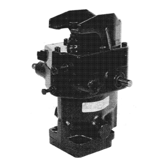
(when viewed from above). The relief valve assembly must be on the right for counterclockwise rotation of the drive. Figure 1-1. Typical SG Governor with New Style Cover Figure 1-2. Early Type SG Governor Speed Adjustment The speed adjusting shaft is used to set the governor for the desired running speed. -
Page 9: Speed Droop Adjustment
Auxiliary Features (Optional) Speed Adjusting Motor The SG governor can be fitted with a speed adjusting motor to enable the switchboard operator to match the frequency of an alternator with that of other units or a system before synchronizing, and to change load distribution after synchronizing. -
Page 10: Chapter 2. Principles Of Operation
Chapter 2. Principles of Operation A schematic arrangement of a typical SG governor is shown in Figure 2-1. As described earlier, the governor uses engine oil as a control medium and does not have an independent sump. The engine oil enters the governor at the relief valve, drops down into the cavity on the suction side of the governor oil pump, and is carried by the pump gears around to the pressure side of the pump. -
Page 11: Figure 2-1. Schematic Diagram Of A Typical Sg Governor
Moving the pin towards the ballhead decreases the speed change; moving it away from the ballhead increases the speed change. Figure 2-1. Schematic Diagram of a Typical SG Governor Woodward DMEnergy (Сервис Генерации) +7 (499) 990-05-50 info@dmenergy.ru... -
Page 12: Chapter 3. Installation And Adjustment
SG Governor Manual 04048 Chapter 3. Installation and Adjustment Installation Introduction These instructions apply to three types of SG governors differentiated by their speed settings: Lever Pneumatic Electric Additional considerations for governors with pneumatic or electric speed setting are listed under respective headings. -
Page 13: Figure 3-1. Recommended Engine Oil System For Quick Starts
Manual 04048 SG Governor If mounted horizontally, the terminal shaft must also be horizontal and a 3/8 inch external drain line provided to connect to either a 1/4-Inch pipe tapped hole or 0.438-20 (-4) straight-thread port In the lower end of the governor cover or subcap. -
Page 14: Figure 3-2. Sg Governor Outline With Direct Pneumatic Speed Setting
SG Governor Manual 04048 Figure 3-2. SG Governor Outline with Direct Pneumatic Speed Setting Figure 3-3. SG Governor Outline with Reverse Pneumatic Speed Setting Woodward DMEnergy (Сервис Генерации) +7 (499) 990-05-50 info@dmenergy.ru www.dmenergy.ru... -
Page 15: Figure 3-4. Sg With Fuel Rod And Bodine Electric Motor For Speed Setting
The permanent magnet motor operates on dc power. If a 115 or 230 Vac or Vdc power source is used, convert the power source to 24 to 32 Vdc. A converter can be ordered from Woodward. See Chapter 1, Speed Adjusting Motor. -
Page 16: Linkage
SG Governor Manual 04048 Figure 3-6. Wiring Diagram for PM Motor (switch not furnished) When the cover is used without the PM motor, a screw is placed in the hole where the motor drive shaft normally fits. This screw is then used as a low-speed stop. -
Page 17: Figure 3-8. Linear Linkage Arrangement
Manual 04048 SG Governor Attach the fuel rack linkage to the governor output shaft. Be sure there is no lost motion or binding in the linkage. See Figure 3-8 for linear linkage arrangement. Be sure to allow sufficient overtravel at each end of the terminal shaft so the governor can shut down the engine and also give maximum fuel when required. -
Page 18: Adjustment
SG Governor Manual 04048 Figure 3-9. Non-linear Linkage Arrangement Adjustment Starting the Engine for the First Time Start the engine as instructed by the engine manufacturer. For a safe start-up, adjust the governor for a reduced speed and allow the engine to warm up. -
Page 19: Troubleshooting
“NO LOAD” TO “FULL LOAD”, droop wilt also be reduced proportionately. Normally, the amount of droop set into the SG governor to make it stable in a system will be enough to allow the units to parallel. Troubleshooting... -
Page 20: Chapter 4. Overhaul
Manual number (this is manual 04048). Part reference number and name or description of part. Exploded views of the most recent and early versions of the SG governor are shown in Figures 5-1 and 5-2. Disassembly Instructions Governor It is suggested that the best mechanic available—preferably one with small parts... - Page 21 Manual 04048 SG Governor Make a note of the distance the high speed stop screw (29/128) protrudes from the governor case so that it can be set approximately the same when reassembling. Remove stop screw (29/1 28), locknut (30/129), and washer (31/—).
- Page 22 SG Governor Manual 04048 12. Remove relief valve assembly as follows: Figure 5-1— Remove oil inlet plug (47) and copper gasket (42). Remove springs (46 and 45). Remove relief valve plunger (60) and sleeve assembly (43). If the plunger and sleeve cannot be removed easily with a small pair of long-nosed pliers (or tweezers) and a hook scriber, leave them in place until step 17.
-
Page 23: Figure 4 1 Bushing Driver
Manual 04048 SG Governor Figure 5-1— Clamp idler gear stud (51) in a vise. Twist and pull the case to remove the stud. Be careful not to score the bottom surface of the case. Drive out plugs (32) and bushings (33 and 38) using a 3/8-inch diameter rod and a piloted driving block similar to that shown in Figure 4-1. -
Page 24: Repair
SG Governor Manual 04048 Relief Valve Previous steps have removed the relief valve elements of governors shown in Figure 5-1. The relief valve assembly in Figure 5-2 will have either plunger (162) or bushing (142) and plunger (143). To remove plunger (162), insert long-nosed pliers in the end of the sleeve, push the plunger down, and grip pin (145). -
Page 25: Assembly Instructions
Manual 04048 SG Governor Pilot Valve Plunger Be extremely careful when polishing the pilot valve plunger control land. Leave the corners sharp. Broken or rounded corners on this land will ruin the pilot valve plunger. Case If the ground bottom surface of the case is grooved or worn from rotation of the pump gears, or scratched from mishandling, it may be surface ground to clean- up. -
Page 26: Figure 4-2. Bushing And Gear Stud Replacement
SG Governor Manual 04048 Figure 4-2. Bushing and Gear Stud Replacement Ballhead Assemblies SOLID BALLHEAD ASSEMBLY (FIGURE 5-1 or 5-2)—Use new ballarm pins (23/121) and lightly upset each end to retain in position. SPRING-DRIVEN OIL-DAMPED BALLHEAD ASSEMBLY (FIGURE 5-8)— Reassemble ballhead components (309 through 314) and then press on ballhead cover (308). - Page 27 Manual 04048 SG Governor Coat the surface of the base with oil. Do not use shellac. Place base seal ring (54/153) in the base groove. If gasket (158, Figure 5-2) is reused, it must not be torn or compressed to less than 0.003 inch (0.08 mm).
-
Page 28: Figure 4-3. Centering Pilot Valve Plunger
SG Governor Manual 04048 Figure 5-8— Remove pipe plug (50, Figure 5-1; 149, Figure 5-2) 50 that the control land on the pilot valve plunger may be observed. Assemble spring seat (304) and nut (303) on pilot valve plunger (305). Do not tighten the nut. - Page 29 Manual 04048 SG Governor Relief Valve Figure 5-1— Be sure relief valve plunger (60) moves freely in relief valve sleeve (43) (plunger installed with small diameter towards inside of governor). The sleeve must fit freely into the case bore. Figure 5-2—...
-
Page 30: Chapter 5. Parts Information
Part reference number as given in the parts list, figure number showing part, and name or description of part. Figures 5-1 and 5-2 illustrate the most common versions of the SG governor. Figures 5-3 through 5-9 illustrate the various optional features which may be used with these governors. -
Page 31: Figure 5-1. Typical Sg Governor Parts (Later Models)
Manual 04048 SG Governor Figure 5-1. Typical SG Governor Parts (later models) Woodward DMEnergy (Сервис Генерации) +7 (499) 990-05-50 info@dmenergy.ru www.dmenergy.ru... -
Page 32: 7 (499) 990-05-50 Info@Dmenergy.ru
SG Governor Manual 04048 Parts List, Figure 5-2 Ref. No. Part Name ......Quantity Ref. No. Part Name ......Quantity 04048-101 Cover ..........1 04048-133 Speed adjusting sleeve ...... 1 04048-102 Low speed stop screw ......1 04048-134 Speed adjusting shaft ......1 04048-103 Hex, nut, 1/4-28 ........ -
Page 33: Figure 5-2. Typical Sg Governor Parts (Early Models)
Manual 04048 SG Governor Figure 5-2. Typical SG Governor Parts (early models) Woodward DMEnergy (Сервис Генерации) +7 (499) 990-05-50 info@dmenergy.ru www.dmenergy.ru... -
Page 34: Cover Assembly With Bodine Speed Adjusting Motor
SG Governor Manual 04048 Cover Assembly with Bodine Speed Adjusting Motor Adjustments A friction coupling is incorporated in these cover assemblies to permit overtravel of the motor with no resulting damage. This coupling should be adjusted to slip at 4.5 to 5.5 lb-in (0.5 to 0.6 Nm) of torque. The motor must be mounted in such a manner as to center the shaft in the coupling. -
Page 35: Figure 5-3. Bodine Speed Adjusting Motor And Installation Parts
Manual 04048 SG Governor Figure 5-3. Bodine Speed Adjusting Motor and Installation Parts Figure 5-4. Speed Adjusting Motor Parts Woodward DMEnergy (Сервис Генерации) +7 (499) 990-05-50 info@dmenergy.ru www.dmenergy.ru... -
Page 36: Cover Assembly With Pittman Pm Speed Adjusting Motor
SG Governor Manual 04048 Cover Assembly with Pittman PM Speed Adjusting Motor Adjustments A friction coupling is incorporated in these cover assemblies to permit overtravel of the motor with no resulting damage. This coupling should be adjusted to slip at 4.5 to 5.5 lb-in (0.5 to 0.6 Nm) of torque and be locked in place with set screw... -
Page 37: Figure 5-5. Pittman Pm Speed Adjusting Motor And Installation Parts
Manual 04048 SG Governor Figure 5-5. Pittman PM Speed Adjusting Motor and Installation Parts Woodward DMEnergy (Сервис Генерации) +7 (499) 990-05-50 info@dmenergy.ru www.dmenergy.ru... -
Page 38: Cover Assembly With Vertical Return Spring
SG Governor Manual 04048 Cover Assembly with Vertical Return Spring Parts List, Figure 5-5a Ref. No. Part Name ........Quantity 04048-361 Hex. screw, 250-28 x 2.250 ..... 1 04048-362 Hex. nut, .250-28, SS ....... 2 04048-363 Washer, 265 x .500 x .032 thick, SS ..2 04048-364 Seal, 1/4 Nitrite thread ...... -
Page 39: Figure 5-5A. Vertical Return Spring Cover And Installation Parts
Manual 04048 SG Governor Figure 5-5a. Vertical Return Spring Cover and Installation Parts Woodward DMEnergy (Сервис Генерации) +7 (499) 990-05-50 info@dmenergy.ru www.dmenergy.ru... -
Page 40: Subcap Assemblies
SG Governor Manual 04048 Subcap Assemblies The parts comprising typical subcap assemblies are shown in Figures 5-6 and 5-7. Except for the subcap assembly, the operation and construction of a governor equipped with a subcap are similar to the conventional governors described in preceding pages. -
Page 41: Figure 5-6. Subcap Assembly Parts (Linear Output)
Manual 04048 SG Governor Figure 5-6. Subcap Assembly Parts (linear output) Woodward DMEnergy (Сервис Генерации) +7 (499) 990-05-50 info@dmenergy.ru www.dmenergy.ru... -
Page 42: Figure 5-7. Subcap Assembly Parts (Internal Return Spring)
SG Governor Manual 04048 Parts List, Figure 5-7 Ref. No. Part Name ........Quantity 04048-275 Vent screw ..........1 04048-276 Shakeproof washer, 1/4 ......1 04048-277 Sems fastener, fil. hd., 10-32 x 1-3/8 ..3 04048-278 Gasket ............. 2 04048-279 Low speed stop screw ...... -
Page 43: Figure 5-8. Spring Driven, Oil-Damped Ballhead Parts
Manual 04048 SG Governor Parts List, Figure 5-8 Ref. No. Part Name ........Quantity 04048-301 Speeder spring assembly ......1 04048-302 Thrust bearing .......... 1 04048-303 Plunger nut ..........1 04048-304 Spring seat ..........1 04048-305 Pilot valve plunger ........1 04048-306 Snap ring .......... -
Page 44: Figure 5-9. Spring-Driven Ballhead Parts
SG Governor Manual 04048 Parts List, Figure 5-9 Ref. No. Part Name ........Quantity 04048-320 Speeder spring ......... 1 04048-321 Pilot valve plunger ........1 04048-322 Thrust bearing .......... 1 04048-323 Retaining ring ........... 1 04048-324 Snap ring..........1 04048-325 Spring coupling assembly ...... -
Page 45: Figure 5-10. Outline Drawing Of Sg Governor With Speed Adjusting Motor
Manual 04048 SG Governor Figure 5-10. Outline Drawing of SG Governor with Speed Adjusting Motor Woodward DMEnergy (Сервис Генерации) +7 (499) 990-05-50 info@dmenergy.ru www.dmenergy.ru... -
Page 46: Figure 5-11. Outline Drawing Of Sg Governor With Subcap (Internal Return Spring) And Speed Adjusting Motor
SG Governor Manual 04048 Figure 5-11. Outline Drawing of SG Governor with Subcap (internal return spring) and Speed Adjusting Motor Woodward DMEnergy (Сервис Генерации) +7 (499) 990-05-50 info@dmenergy.ru www.dmenergy.ru... -
Page 47: Figure 5-12. Outline Drawing Of Sg Governor With And Without Pm Motor, With Pneumatic Speed Setting Assembly
Manual 04048 SG Governor Figure 5-12. Outline Drawing of SG Governor with and without PM Motor, with Pneumatic Speed Setting Assembly Woodward DMEnergy (Сервис Генерации) +7 (499) 990-05-50 info@dmenergy.ru www.dmenergy.ru... -
Page 48: Chapter 6. Troubleshooting
Oil contaminated with water will cause foaming. Dirty oil causes approximately 75% of all SG governor troubles. Change the engine lubricating oil more often than essential for engine maintenance purposes if proper filters are not used in the supply line to the governor. - Page 49 Manual 04048 SG Governor Trouble Cause Correction 1. Engine hunts or A. Speed droop adjustment Increase speed droop. surges. incorrect. B. Dirty oil in governor. Clean governor, change engine oil if necessary. C. Foamy oil supplied to Drain engine oil. Refill.
- Page 50 SG Governor Manual 04048 Trouble Cause Correction 4. Load does not A. Speed droop adjustment 1. Readjust droop to divide toad divide properly on incorrect. properly. inter-connected 2. Increase droop to resist picking up engines. (or dropping off) load. 3. Reduce droop to increase picking up (or dropping off) load.
-
Page 51: Chapter 7. Product Support And Service Options
A current list of Woodward Business Partners is available at www.woodward.com/directory. Product Service Options Depending on the type of product, the following options for servicing Woodward products may be available through your local Full-Service Distributor or the OEM or Packager of the equipment system. -
Page 52: Returning Equipment For Repair
To prevent damage to electronic components caused by improper handling, read and observe the precautions in Woodward manual 82715, Guide for Handling and Protection of Electronic Controls, Printed Circuit Boards, and Modules. -
Page 53: Engineering Services
Field Service engineering on-site support is available, depending on the product and location, from one of our Full-Service Distributors. The field engineers are experienced both on Woodward products as well as on much of the non- Woodward equipment with which our products interface. -
Page 54: Technical Assistance
Manual 04048 Technical Assistance If you need to contact technical assistance, you will need to provide the following information. Please write it down here before contacting the Engine OEM, the Packager, a Woodward Business Partner, or the Woodward factory: General... -
Page 55: Revision History
Manual 04048 SG Governor Revision History Changes in Revision D— Revision advanced to coordinate with new installation sheet, and to update manual to latest formats and safety warnings. Woodward DMEnergy (Сервис Генерации) +7 (499) 990-05-50 info@dmenergy.ru www.dmenergy.ru... - Page 56 Email and Website—www.woodward.com Woodward has company-owned plants, subsidiaries, and branches, as well as authorized distributors and other authorized service and sales facilities throughout the world. Complete address / phone / fax / email information for all locations is available on our website.
Need help?
Do you have a question about the SG Governor and is the answer not in the manual?
Questions and answers