Woodward L-Series Installation And Operation Manual
Position controller
Hide thumbs
Also See for L-Series:
- Installation and operation manual (130 pages) ,
- Installation and operation manual (34 pages)

Subscribe to Our Youtube Channel
Related Manuals for Woodward L-Series


Summary of Contents for Woodward L-Series
- Page 1 Installation and Operation Manual L-Series Position Controller Manual 26237 (Revision F)
- Page 2 Revisions—Text changes are indicated by a black line alongside the text. Woodward Governor Company reserves the right to update any portion of this publication at any time. Information provided by Woodward Governor Company is believed to be correct and reliable. However, no responsibility is assumed by Woodward Governor Company unless otherwise expressly undertaken.
-
Page 3: Table Of Contents
PTIONS Product Service Options ..................51 Returning Equipment for Repair ................52 Replacement Parts ....................53 How to Contact Woodward ................... 53 Engineering Services .................... 54 Technical Assistance .................... 55 A. A ..........56 ... - Page 4 Figure 3-3b. L-Series Shaft Types ................ 18 Figure 3-3c. L-Series Shaft Types ................ 19 Figure 3-4. Typical L-Series Position Control Application Wiring ......21 Figure 3-5. Acceptable PWM Input Types ............23 Figure 3-6. Relay Driver Output ................24 ...
-
Page 5: Regulatory Compliance
L-Series Position Controller Regulatory Compliance The L-Series is suitable for use in Class I, Division 2, Groups A, B, C, D per CSA for Canada and U.S. or non-hazardous locations only. Wiring must be in accordance with North American Class I, Division 2 wiring methods as applicable, and in accordance with the authority having jurisdiction. -
Page 6: Electrostatic Discharge Awareness
PCB from the control cabinet, place it in the antistatic protective bag. CAUTION—ELECTROSTATIC DISCHARGE To prevent damage to electronic components caused by improper handling, read and observe the precautions in Woodward manual 82715, Guide for Handling and Protection of Electronic Controls, Printed Circuit Boards, and Modules. Woodward... -
Page 7: Chapter 1. General Information
OEMs themselves may find it useful to copy some of the information from this manual into their application user manuals. How to Use This Manual The following summarizes how to install a L-Series actuator into a new or existing system: •... -
Page 8: Programmable Features
More detail on the features of the L-Series can be found later in this manual. WARNING—EMERGENCY STOP When included with an ITB, the actuator depends solely on the return spring... -
Page 9: Service Tool Software
Manual 26237 L-Series Position Controller Service Tool Software The L-Series Service Tool software is a Microsoft Windows based GUI (graphic user interface). The Service Tool Software is compatible with Windows 95/98/NT/00 and gives the OEM the ability to: • Configure product settings based on application requirements •... -
Page 10: Chapter 2. System Description/Application Overview
Service Tool Driver Input Power The L-Series will handle a voltage range of 10 to 28 Vdc at full specified torque. The actuator is functional in the range of 8 to 32 Vdc, but accuracy and/or torque can be diminished at the extreme ends of this range. - Page 11 Run Enable (optional) Position Command Signal The L-Series can accept either a PWM command signal input or an analog 0–5 Vdc command signal input, depending on how the software application is configured. The PWM will function with various types of input sources, including high-side, low-side open collector, and push-pull—depending on the configuration.
-
Page 12: Figure 2-1. Pwm Linear Demand To Position
L-Series Position Controller Manual 26237 user-defined shutdown failsafe direction user-defined shutdown failsafe direction PWM Position Signal Duty Cycle, % Figure 2-1. PWM Linear Demand to Position user-defined shutdown failsafe direction user-defined points PWM Position Signal Duty Cycle, % Figure 2-2. PWM Non-Linear Demand to Position The 0–5 V input uses a different pin in the connector, and it has a usable range... -
Page 13: Figure 2-3. Analog 0-5 V Linear Demand To Position
Manual 26237 L-Series Position Controller user-defined shutdown failsafe direction user-defined shutdown failsafe direction Position Signal Voltage Figure 2-3. Analog 0–5 V Linear Demand to Position user-defined shutdown failsafe direction user-defined points Position Signal Voltage Figure 2-4. Analog 0–5 V Non-Linear Demand to Position Discrete Output A discrete output is provided to serve as a status indicator. -
Page 14: Communications
Chapter 3 (Installation). 5V Output—A 5 Vdc output has been provided on the L-Series actuator to power external sensors, if necessary. The 5 V output is limited to 10 mA, but this is sufficient for most light-duty ratiometric sensors. -
Page 15: Temperature Sensing
The service port is provided for configuration and setup only. Temperature Sensing The L-Series has an on-board temperature sensor to monitor board temperatures and protect the unit from overtemperature. This temperature is monitored and a fault is annunciated if the set point is exceeded. - Page 16 L-Series Position Controller Manual 26237 Brownout Reset Brownout Reset is true if CPU Voltage drops below 4.2 V but not below 1 V. The brownout detect circuit will reset the CPU. This is a hard-coded alarm. If detected, the control will attempt to continue normal operation.
- Page 17 Manual 26237 L-Series Position Controller Can be configured as an alarm or shutdown. If configured as a shutdown, the control will go limp if this fault is detected. If configured as an alarm, the control will attempt to continue normal operation if this fault is detected.
- Page 18 L-Series Position Controller Manual 26237 Run Enable Shutdown Run Enable discrete input is opened, only active when this input is configured for use. This is a hard-coded shutdown. The control will go limp if this condition is detected. Woodward...
-
Page 19: Chapter 3. Installation
L-Series Position Controller Chapter 3. Installation Introduction This chapter provides instructions on how to mount and connect the L-Series controller into a system. Hardware dimensions are provided for mounting the device to a specific application. WARNING—NOISE Due to typical noise levels in turbine or engine environments, hearing protection should be worn when working on or around the L-Series. -
Page 20: Unpacking
The operating temperature range of the control is –40 to +105 °C (–40 to +221 °F). In spark-ignited applications, make sure the L-Series is located away from the ignition coil, and that harness wires are not routed next to the spark plug wires. -
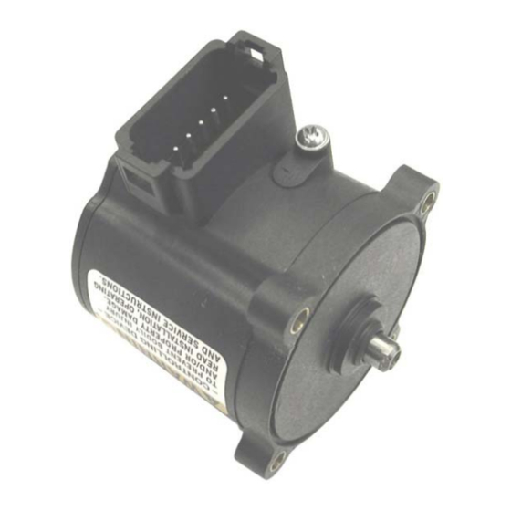
Page 21: Figure 3-1. L-Series Outline Drawing
Manual 26237 L-Series Position Controller Figure 3-1. L-Series Outline Drawing Woodward... -
Page 22: Figure 3-2. L-Series Cover Types
L-Series Position Controller Manual 26237 Figure 3-2. L-Series Cover Types Woodward... -
Page 23: Figure 3-3A. L-Series Shaft Types
Manual 26237 L-Series Position Controller Figure 3-3a. L-Series Shaft Types Woodward... -
Page 24: Figure 3-3B. L-Series Shaft Types
L-Series Position Controller Manual 26237 Figure 3-3b. L-Series Shaft Types Woodward... -
Page 25: Electrical Installation
L-Series Position Controller Figure 3-3c. L-Series Shaft Types Electrical Installation A wiring pinout of the L-Series control, as viewed by looking into the control’s connector feature, is shown in Figure 3-4. Typical connections to external devices are also shown. Woodward... - Page 26 L-Series Position Controller Manual 26237 The L-Series has an operating voltage range of 8 to 32 Vdc with nominal voltages of 12 or 24 Vdc. The power supply is reverse polarity protected, and consumes 32 W maximum power at a peak current of 1 A (32 V) assuming 4 Ω...
-
Page 27: Description Of Electrical I/O
Representative circuitry for the L-Series inputs/outputs is provided in Figure 3-5 below. Power Supply Input (+12 Vdc/24 Vdc at pin 1, ground at pin 5)—The L-Series is configured for 12 or 24 V nominal operation, although it will handle 8–32 V. The... - Page 28 Woodward recommends using a 6 A slow-blow fuse on the power supply line feeding pin 1 of the L-Series actuator. WARNING—FUSED INPUT POWER The input power must be fused. Failure to fuse the L-Series could, under exceptional circumstances, lead to personal injury, damage to the control valve, and/or explosion.
-
Page 29: Figure 3-5. Acceptable Pwm Input Types
Manual 26237 L-Series Position Controller For this type of PWM Source..the L-Series PWM Input looks like... High-Side Open-Collector (open-drain) PWM Source L-Series Configured for “Pull-Down” 5 - 32 VDC L-Series Pin 11 PNP (or P-Channel FET) 4 kW 9.5 kW... -
Page 30: Figure 3-6. Relay Driver Output
By default, this circuit will be configured in a failsafe manner, meaning it will be active (conducting) when no fault exists, but if power is lost or a fault is detected by the L-Series actuator, the circuit will open. See Figure 3-6 below for typical usage of this feature. -
Page 31: Figure 3-7. Typical Aux1 And Aux2 Usage
0.5V to 4.5VDC Processor Command Signal 1000pF 499k ** if optional external Run Enable is chosen during L-Series configuration, Aux. 1 can be used to enable or disable the actuator output shaft torque. Figure 3-7. Typical AUX1 and AUX2 Usage Woodward... -
Page 32: Figure 3-8. Ground Junction Point
THERE IS NOT AN INTERNAL CONNECTION TO CIRCUIT GROUND. Terminal pins 3 and 5 must be used for access to the circuit ground. This junction point is completely electrically isolated from the L-Series actuator’s electronics, and is solely for convenience during installation. -
Page 33: Chapter 4. Service Tool
Service Tool Introduction This chapter covers the process of tuning, configuring, calibrating, and servicing the control via the L-Series Service Tool. It is assumed that the control has already been installed on the engine. NOTE Many applications are delivered pre-configured, calibrated, and tuned. These units do not require the use of the Service Tool. -
Page 34: Figure 4-2A. Typical Programming Datalink Harness Wiring
CAUTION—SERIAL PORT DAMAGE POTENTIAL There is a potential for serial port damage when communicating with the L-Series control. This is caused by a difference in ac voltage between neutral and earth ground. If the PC RS-232 port ground is referenced to ac neutral, and the L-Series control is referenced to battery ground (ac earth ground), a large amount of current can be experienced. -
Page 35: Getting Started
What to do next After the software is installed, connect a serial communications cable between the RS-232 connections on the L-Series control and an unused serial port on your computer. Run the Service Tool program and select the appropriate comm port. -
Page 36: L-Series Configuration
Software Version Identification The Service Tool software version can found by selecting ‘About’ under the Help menu. The L-Series software version can be found on the right-most tab sheet (Identification) of the Service Tool screen. The Service Tool and Control must be connected to view this information. -
Page 37: Configuration Parameters
Manual 26237 L-Series Position Controller Configuring the Unit—Off-Line Unit configuration is summarized as follows: • Open the Configuration Editor Dialog using the File/New or File/Open options. • Edit the configuration settings. • Save the configuration to a file. At a later date simply open the configuration and load it into the control. -
Page 38: Figure 4-4. Configuration Editor-Analog Settings
L-Series Position Controller Manual 26237 Figure 4-4. Configuration Editor—Analog Settings Proportional Gain Sets the position controller PID’s proportional gain. Increased gain corresponds to increased PID output (higher proportional = faster response). This setting can also be dynamically adjusted using the PID Tuning screen. Allowed values: 0–... - Page 39 PWM (see Figure 4-5). PWM Pull Up Select Selects the appropriate PWM source. This configures the L-Series input internally to provide the proper pull-up logic. For details on selection of this parameter, refer to Chapter 3. Allowed values: Push-Pull, High Side Drive, or Low Side Drive.
-
Page 40: Figure 4-5. Configuration Editor-Pwm Settings
L-Series Position Controller Manual 26237 Figure 4-5. Configuration Editor—PWM Settings Discrete Output Tab Sheet This screen contains the discrete output configuration settings. If the discrete output is not used, then these settings can be skipped. Relay Output Configuration The relay output can be configured to one of the following:... -
Page 41: Figure 4-6. Configuration Editor-Discrete Output Settings
Manual 26237 L-Series Position Controller Figure 4-6. Configuration Editor—Discrete Output Settings Alarm/Shutdown Tab Sheet This screen contains the alarm and shutdown configuration settings. Shutdown/Alarm Fault Selections The list of faults displayed can be individually selected to either perform a Shutdown or just Alarm (no action). -
Page 42: Figure 4-7. Configuration Editor-Alarm/Shutdown Settings
L-Series Position Controller Manual 26237 Figure 4-7. Configuration Editor—Alarm/Shutdown Settings Loading the Configuration (Save) Select the File/Load to Control from the menu or Blue Arrow icon on the Configuration Editor to load the changes into the control. Monitoring the Driver The Service Tool has five different tab sheets to monitor driver parameters. -
Page 43: Figure 4-8. Service Tool-Overview Tab
L-Series Position Controller Communication Status This section of the status bar shows the status of communication between the service tool and the L-Series Driver. For more information, see Establishing Communication. • Connected—The Service Tool is connected to and communicating with the driver. - Page 44 L-Series Position Controller Manual 26237 Supply Voltage Displayed value of the input power, in volts, as read by the processor. Power Demand Displayed value of the power demanded, in watts, as read by the processor. This is an indication of the work output.
-
Page 45: Figure 4-9. Service Tool-Alarms Tab
Latched faults can be cleared by cycling power on the L-Series control or by selecting the ‘Reset Alarms and Shutdowns’ button on any of the Alarm or Shutdown screens. -
Page 46: Figure 4-10. Service Tool-Shutdowns Tab
L-Series Position Controller Manual 26237 Figure 4-10. Service Tool—Shutdowns Tab Figure 4-11. Service Tool—Internal Shutdowns Tab Woodward... -
Page 47: Figure 4-12. Service Tool-Identification Tab
To get to the PID Tuning screen, select the Edit Position PID from the Tools menu selection. The L-Series controller can be put into a manual control mode from this screen by selecting the “Enable Manual Position Tuning’ checkbox (Figure 4-13). Once in manual mode, the position setpoint box is highlighted and the value displayed is actively positioning the output. -
Page 48: Position Calibration And Verification
L-Series Position Controller Manual 26237 Figure 4-13. Service Tool—PID Tuning Window Figure 4-14. Service Tool—PID Tuning Properties Window Position Calibration and Verification Position calibration is available to map the position command input to the actual rotational travel of the unit. It is only used when the full travel of the actuator is constrained or limited such that 0 to 60 degrees of travel is not used. -
Page 49: Calibration Sequence Overview
1. Select Automatic Position Calibration Mode. 2. Select cw or ccw Direction. 3. L-Series automatically rotates in both cw and ccw directions until the stops are detected. The values are then captured and stored. 4. When completed, cycle the power on the L-Series. -
Page 50: Figure 4-15. Service Tool-Verify Position Calibration
L-Series Position Controller Manual 26237 The Full Travel Actual Position is the full stroke factory position without user stops after software linearization. The Full Travel Sensor Position is the full stroke factory position without user stops before software linearization. The Full Travel Sensor Position will match the TPS Output Signal. -
Page 51: Figure 4-16. Service Tool-Manual Position Calibration
Manual 26237 L-Series Position Controller Figure 4-16. Service Tool—Manual Position Calibration The next screen is used to set the minimum and maximum positions for the user soft stops. To find the minimum and maximum soft stops use the verify position mode described above to position the valve and use the Full Travel Actual Position reading for minimum and maximum position values. -
Page 52: Figure 4-18. Service Tool-Auto Position Calibration
L-Series Position Controller Manual 26237 Automatic The automatic calibration mode is used to set the minimum position and fail direction and to calibrate the valve to user physical stops (mechanical hard stops). Like the manual mode, the first screen to appear is used to set the minimum position and fail direction. -
Page 53: Chapter 5. Troubleshooting
For more detailed information about governor system failure modes and effects, contact Woodward for a copy of the system DFMEA. The troubleshooting scenarios listed below assume that the end user has a digital multimeter at his disposal for testing voltages and checking continuity, and assume that the application has been engineered and tested thoroughly. -
Page 54: Engine/Generator Troubleshooting
L-Series Position Controller Manual 26237 Engine/Generator Troubleshooting Problem Possible Cause Suggested Test/Correction Engine does not Stuck throttle/frozen shaft Move throttle by hand. Assess start smoothness, friction, and return spring force. Power not applied to control Disconnect starter motor solenoid. Disconnect harness from governor. - Page 55 Verify the port setting is correct. Service Tool not Old version of Service Tool Re-install Service Tool, get the latest communicating– or file corruption or bad version from the Woodward web site ‘Error message install. (www.woodward.com) displayed on PC when trying to...
-
Page 56: Electrical Troubleshooting Guide
Verify the input is properly configured. Alarm or Shutdown Conditions If the L-Series control has any alarm or shutdown conditions, refer to Chapter 2 for details on the exact cause of the condition. The Service Tool must be used to determine the cause of any shutdown or alarm condition. -
Page 57: Chapter 6. Service Options
Product Service Options The following factory options are available for servicing Woodward equipment, based on the standard Woodward Product and Service Warranty (5-01-1205) that is in effect at the time the product is purchased from Woodward or the service is performed: •... -
Page 58: Returning Equipment For Repair
Returning Equipment for Repair If a control (or any part of an electronic control) is to be returned to Woodward for repair, please contact Woodward in advance to obtain a Return Authorization Number. When shipping the item(s), attach a tag with the following information: •... -
Page 59: Replacement Parts
To expedite the repair process, contact Woodward in advance to obtain a Return Authorization Number, and arrange for issue of a purchase order for the item(s) to be repaired. No work can be started until a purchase order is received. -
Page 60: Engineering Services
L-Series Position Controller Manual 26237 Engineering Services Woodward Industrial Controls Engineering Services offers the following after- sales support for Woodward products. For these services, you can contact us by telephone, by email, or through the Woodward website. • Technical Support •... -
Page 61: Technical Assistance
Type of Fuel (gas, gaseous, steam, etc) Rating Application Control/Governor Information Please list all Woodward governors, actuators, and electronic controls in your system: Woodward Part Number and Revision Letter Control Description or Governor Type Serial Number Woodward Part Number and Revision Letter... -
Page 62: Appendix A. Acronyms/Abbreviations
Isoch isochronous integrated throttle body L-Series Woodward electronic engine governor that contains both a rotary actuator and a controller circuit board magnetic pick up original equipment manufacturer pulse-width modulated revolutions per minute RS-232 a communications standard... -
Page 63: Appendix B. L-Series Configuration Summary
Manual 26237 L-Series Position Controller Appendix B. L-Series Configuration Summary APPLICATION ________________________________________________ ACTUATOR SERIAL NUMBER ____________________________________ For details on individual settings, refer to Chapter 4. Configuration Settings – Position Controller Setup Position Demand Selection PWM ____ 0..5 V ____ Fail Direction... -
Page 64: Appendix C. L-Series Control Specifications
L-Series Position Controller Manual 26237 Appendix C. L-Series Control Specifications Specifications Power Supply 12/24 V systems (10–32 Vdc) reverse polarity protection, 2.5 A max Power Consumption 32 W maximum Torque Nominal: 0.34 N m (0.25 lb-ft) Minimum Transient (up to 105 °C): 0.28 N m (0.21 lb-ft) - Page 65 Reliability and Quality Goals The L-Series control system has a reliability target of 17 500 hours MTBF. It also has a quality goal of less than 25 PPM when measuring out-of-the-box defects. This quality goal is a target based on continuous improvement.
- Page 66 L-Series Position Controller Manual 26237 Discrete Input Parameter Value Input Current 0.5 mA @ 5 Vdc Input Type Ground referenced discrete input Delay Time for Shutdown < 200 ms for system to recognize shutdown Delay Time for Reset < 1 s for valves to move to minimum position...
-
Page 67: Figure C-1. Bode Plot Of L-Series Response
Position Demand Algorithms 6.5 ms Analog Input Logic 6.5 ms PWM Input Logic 6.5 ms Serial Port background task Run Enable Discrete Input 6.5 ms Discrete Output 6.5 ms Diagnostics 6.5 ms Figure C-1. Bode Plot of L-Series Response Woodward... - Page 70 Phone +1 (970) 482-5811 • Fax +1 (970) 498-3058 Email and Website—www.woodward.com Woodward has company-owned plants, subsidiaries, and branches, as well as authorized distributors and other authorized service and sales facilities throughout the world. Complete address / phone / fax / email information for all locations is available on our website.
Need help?
Do you have a question about the L-Series and is the answer not in the manual?
Questions and answers