Kessel aqualift f Installation, Operating And Maintenance Instructions
Wastewater with and without sewage for
free-standing installation in frost protected rooms
Hide thumbs
Also See for aqualift f:
- Installation and operating manual (216 pages) ,
- Instructions for installation, operation and maintenance (180 pages) ,
- Installation and operating instructions manual (112 pages)
Table of Contents
Advertisement
Available languages
Available languages
Quick Links
ANLEITUNG FÜR EINBAU, BEDIENUNG UND WARTUNG
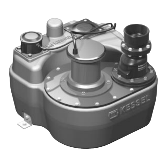
KESSEL-Hebeanlage qualift F (230V)
für fäkalienhaltiges und fäkalienfreies bwasser
zur freien ufstellung in
frostgeschützten Räumen
Hebeanlage qualift
Installation
der Anlage wurde durchgeführt von Ihrem Fachbetrieb:
Name/Unterschrift
Stand 05/2012
€
(230 V)
Inbetriebnahme
Datum
Einweisung
Ort
Bedienungsanleitung
Seite 1-36
Installation Manual
Page 37-72
Guide L´Installation
Pagina 73-108
Istruzione Installazione
Pagina 109-144
Handleiding voor inbouw
Pagina 145-180
Produktvorteile
Einfacher Anschluß über
angeformte Stutzen
Anbohrflächen für weitere
Anschlüsse
Vollautomatischer Betrieb
Wartungsfreundlicher
PE-Behälter
Allgemeine bauaufsichtliche
Zulassung Nr. Z-53.2-424
Stempel Fachbetrieb
Sach-Nr. 206-817
Advertisement
Chapters
Table of Contents

Related Manuals for Kessel aqualift f


Summary of Contents for Kessel aqualift f
- Page 1 ANLEITUNG FÜR EINBAU, BEDIENUNG UND WARTUNG Bedienungsanleitung KESSEL-Hebeanlage qualift F (230V) Seite 1-36 Installation Manual Page 37-72 für fäkalienhaltiges und fäkalienfreies bwasser Guide L´Installation Pagina 73-108 zur freien ufstellung in Istruzione Installazione Pagina 109-144 frostgeschützten Räumen Handleiding voor inbouw Pagina 145-180 €...
-
Page 2: Table Of Contents
Inhaltsverzeichnis ......................Seite 1. Sicherheitshinweise Einsatzbereich ..............Seite 2. Allgemeines Anlagenbeschreibung............Seite Abmessungen..............Seite 3. Technische Daten Pumpe .................Seite Schaltvolumen ..............Seite 3.4. Elektrisches Schaltgerät ............Seite Montage Sammelbehälter ...........Seite 4. Einbau und Montage Anschluß der Rohrleitungen ..........Seite Einstellung der Druckniveauschalter ........Seite Allgemeine Hinweise ............Seite 12 5. - Page 3 1. Sicherheitshinweise Allgemeine Sicherheitsvorkehrungen Bei Installation, Betrieb, Wartung oder Reparatur der Anlage sind die Unfallverhütungsvorschriften, die in Frage kommenden DIN- und VDE-Normen und Richtlinien sowie die Vorschriften der örtlichen Ener - gie- und Versorgungsunternehmen zu beachten. Die Anlagen dürfen nicht in explosionsgefährdeten Bereichen betrieben werden. Gefahr durch elektrische Spannung Diese Anlage enthält elektrische Spannungen und steuert drehende, mechanische Anlagenteile.
- Page 4 Sehr geehrter Kunde, wir freuen uns, daß Sie sich für ein Produkt von KESSEL entschieden haben. Die gesamte Anlage wurde vor Verlassen des Werkes einer strengen Qualitätskontrolle unterzogen. Prüfen Sie bitte den- noch sofort, ob die Anlage vollständig und unbeschädigt bei Ihnen angeliefert wurde. Im Falle eines Transportschadens beachten Sie bitte die Anweisungen in Kapitel „Gewährleistungen“...
-
Page 5: Einsatzbereich
2. Allgemeines 2.1 Einsatzbereich Die Hebeanlagen fördern die unterhalb der Kanal- und Rück- Die KESSEL-Hebeanlage Aqualift F ist zur freien Aufstel- ® stauebene anfallenden fäkalienhaltigen und fäkalienfreien lung in frostgeschützten Räumen vorgesehen. Das zuge hö - Ab wässer entsprechend den Vorschriften der DIN 1986 voll- ri ge Schaltgerät ist in einem überflutungssicheren, trockenen... -
Page 6: Abmessungen
3. Technische Daten 3.1 Abmessungen Einzelanlage 1,1 kW mit Druckabgang DN 100, Best. Nr. 28646 DN100 Ø110 DN70 Ø75 ISO-Ansicht... -
Page 7: Pumpe
3. Technische Daten 3.2 Pumpe 230 V - 1,1 kW Nennleistung (P2) 1,1 kW Aufnahmeleistung (P1) 1,7 kW Betriebsspannung 230 V Nennfrequenz 50 Hz Nennstrom 7,3 A Anlaufstrom 18,5 A Betriebskondensator 40 µF; 400 V AC DB Absicherung 10 A träge Anschlußleitung 5 m Länge, 7 x 1,5 mm Förderguttemperatur... -
Page 8: Schaltvolumen
3. Technische Daten 3.3 Schaltvolumen 3.4.3 Eingänge Niveaueingänge „Ein“ und „Niveau“ Das Schaltvolumen beträgt ca. 20 l bei der serienmäßigen Einstellung der Druckniveauschalter und der voreingestell- Versorgungsspannung jeweils 6 V DC, Schaltstrom jeweils ten Konfi gu ration des Schaltgerätes. 10 mA Temperaturschalter des Motors Versorgungsspannung 12 V DC, Schaltstrom ON = 9 mA,... -
Page 9: Montage Sammelbehälter
Die Anlage ist an entprechender Stelle im Raum waagrecht Abb. A: Einzelanlage aus zurichten und zweckmäßig auf schalldämmendem Mate - rial (als Zubehör bei KESSEL erhältlich) aufzustellen. Die He beanlage ist mit den mit gelieferten Winkeln, Schrauben Über den Stutzen kann eine handelsübliche Kunststoffrohr- und Dübeln fest mit dem Boden zu verbinden, um sie gegen... - Page 10 Stutzen absägen Rohranschluß Behälter-Hebeanlage Zulauf-Anschluß Abb. E * KESSEL-Zubehörteil Behälter-Hebeanlage Bei allen seitlich angebohrten Anschlüssen ist zu be rück - WICHTIG: sich tigen, daß die Niveausteuerung so eingestellt ist, daß im Normalbetrieb der Wasserstand im Be häl ter bis zur Abb.
-
Page 11: Einstellung Der Druckniveauschalter
4. Einbau und Montage Die Zulaufleitung ist mit einem Gefälle entsprechend EN 12056 zur KESSEL-Hebeanlage zu verlegen und möglichst 4.3 Niveausteuerung ge rade zu führen. Zu tief angebrachte Zuläufe können zu Verstopfungen in den Zulaufleitungen führen (siehe auch S. Vor allen Arbeiten am Schaltgerät, an der Pumpe oder an ACHTUNG: 10 “Wichtig”). -
Page 12: Allgemeine Hinweise
5. Elektroanschluss Der Anschluß von Pumpe und Druckniveauschalter am Schaltgerät wurde bereits werkseitig durchgeführt. 5.2 Montage des Schaltgeräts Installieren Sie das mitgelieferte Schaltgerät in einem frost- Unabhängig davon sind die nachfolgenden Ausführungen in freien, trockenen, überflutungssicheren und gut belüfteten diesem Kapitel detailliert zu befolgen. Sofern Arbeiten be- Raum. -
Page 13: Installation, Verdrahtung
5. Elektroanschluss 5.3 Installation, Verdrahtung Die Anschlußleitungen sind gemäß Anschlußplan (siehe Ab- schnitt 9) anzuschließen. Dazu zunächst in den Kabelver- schraubungen die Dichtung mit ei nem Schraubenzieher durchstoßen (Bild a), die Leitung einführen (Bild b) und an- klemmen (Bild c). Anschließend kann die Mutter der Kabel- verschraubung mit der Hand festgezogen werden (Bild d). -
Page 14: Abschluß Der Elektroarbeiten
5. Elektroanschluss Die einzelnen Anschlußarbeiten sind in der nachfolgenden Tabelle sowie im Anschlußplan auf der Seite 28 auf geführt. Zu beachten sind dabei auch die jeweiligen Erläuterungen in Kapitel9, Elektrisches Schaltgerät (Lage der Bedienelemente, In- nenansicht des Schaltgerätes). EINZELANLAGE - Sicherheitshinweise beachten ! Auszuführende Arbeit Beschreibung •... -
Page 15: Allgemeine Hinweise
6. Inbetriebnahme 6.1 Allgemeine Hinweise 6.2 Druckabgangsstutzen Für die Inbetriebnahme von Hebeanlagen ist die DIN 1986, Die Druckabgangsstutzen der Hebeanlagen sind für jede Teil 31, zu beachten. Pumpe standardmäßig mit einer Rückschlagklappe mit An- lüftevorrichtung versehen. Die Anlüftevorrichtung muß immer in Betriebsstellung sein (siehe Abb. 1). Vor Inbetriebnahme sind die Zulaufleitungen und die Die Öffnung der Klappe (gestrichelt) erfolgt ausschließlich ACHTUNG:... -
Page 16: Normalbetrieb
6. Inbetriebnahme Wenn der Probelauf erfolglos war, wird Temperaturfehler an- gezeigt. Wenn ein anderer Fehler vorliegt, wird dieser eben- 6.5 Handbetrieb falls angezeigt. Die Anlage ist in beiden Fällen nicht be- Wenn die Anlage im Normalbetrieb ist, kann durch Drücken triebsbereit. -
Page 17: Werkseitige Voreinstellungen
6. Inbetriebnahme • Die Pumpe wird wieder eingeschaltet (erster Wiederein- wäre nichts vorgefallen. Beim nächsten Überstrom sind schaltversuch). dann wieder bis zu drei Wiedereinschaltversuche möglich. • Das Schaltgerät überprüft, ob der Pumpenmotor einen Überstrom aufnimmt. • Erst nach dem dritten erfolglosen Wiedereinschaltversuch •... -
Page 18: Verändern Von Einstellungen
6. Inbetriebnahme Um in die 1. bis 4. Einstellung zu gelangen: Für die 2. bis 4. Einstellung den Vorgang entsprechend oft • Die Tasten „Alarm“ und „Pumpe“ gemeinsam drücken. wiederholen. ➤ Es ertönt ein akustisches Signal. ➤ Es leuchtet die LED „Netz“ (1. Einstellung). Um die Einstellungen wieder zu verlassen: •... -
Page 19: Hinweise Zur Pumpe
7. Inspektion und Wartung Die Anlage ist monatlich vom Betreiber durch Beobachtung ei nes Schaltspiels auf Betriebsfähigkeit und Dichtheit zu 7.2 Hinweise zur Anlüftevorrichtung über prüfen. Mit der Anlüftevorrichtung kann die Druckleitung durch ma- nuelles Anheben der Rückschlagklappe der Hebeanlage komplett entleert werden. -
Page 20: Hinweise Zum Elektrischen Schaltgerät
7. Inspektion und Wartung Durch Lösen der Verschraubungen am unteren und obe- Hinweis: 7.3 Hinweise zum elektrischen Schaltgerät ren Flansch des Klappengehäuses kann für Reinigungs- • Nach Wartungsarbeiten muß der Gehäusedeckel wieder und Wartungszwecke das gesamte Klappengehäuse ab- fachgerecht verschlossen wer den. genommen werden (siehe Abb. -
Page 21: Anzeige Von Warnungen Und Fehlern
8. Warnungen, Fehler und Abstellmaßnahmen 8.2 Anzeige von Warnungen und Fehlern Anzeige Störungsursache Folge für den Prozeß Ursache nicht mehr Verschlüsselung für beim Auftreten vorhanden die Anzeige letzte Warnung / Fehler LED „Alarm“ blinkt Grenzlaufzeit über- LED „Alarm“ blinket LED’s „Netz“ und Warnung schritten bei Niveau- „Alarm“... -
Page 22: Behebung Von Warnungen Und Fehlern
8. Warnungen, Fehler und Abstellmaßnahmen 8.3 Behebung von Warnungen und Fehlern Beschreibung, Auswirkungen auf Auswirkungen Abhilfemaßnahme/ Entstehungsursache den akustischen auf den poten- Störungsbeseitigung Alarm tialfreien Kontakt Grenzlaufzeit (bei Die eingestellte Laufzeit wird eingeschaltet Relais bleibt • Zulauf überprüfen Warnungen Niveausteuerung wurde überschritten (zu angezogen •... -
Page 23: Allgemeine Störungen
• Fremdkörper in der Druckarmatur oder in der Druckleitung entfernen • Pumpen sind abgenutzt, Austausch vorneh- men lassen • Falsche Auslegung der Hebeanlage, Klärung über KESSEL-Kundendienst Drehrichtung prüfen, bei falscher Drehrichtung Falsche Motordrehrichtung elektrischen Anschluß überprüfen Pumpe läuft rauh oder laut Pumpe und Motor überprüfen;... - Page 24 Anlage auf Schaltstörungen prüfen (vor allem Beißender Geruch Motorschutzschalter) Zu häufiges Ein- und Ausschalten der Anlage durch zu hohe Zulaufmengen, Klärung mit KESSEL-Kundendienst Schütze zu heiß durch Schalt- Anlage auf Schaltstörungen prüfen. störungen Zulaufmenge zu hoch durch Ursachen feststellen und beseitigen Fremdwasser o.ä.
-
Page 25: Unlogische Schalterstellungen Der Niveauschalter
8. Warnungen, Fehler und Abstellmaßnahmen Folgende Schaltfehler kann das Schaltgerät nicht erkennen: • Der Alarm-Niveau-Schalter schließt nicht: 8.5 Unlogische Schalterstellungen der Niveauschalter Das Schaltgerät überwacht bei den beiden Niveauschaltern Das Schaltgerät erliegt der Täuschung, daß das Alarm- Ein und Alarm Niveau nie überschritten wird. -
Page 26: Allgemeine Beschreibung
9. Schaltgerät 9.1 Allgemeine Beschreibung Gehause Schaltgerät Orange LED „Pumpe“ 4x PT-Schraube max. (1 Nm) Taste „Alarm“ Netzanschlussleitung Taste „Pumpe“ Kurzbedienungsanleitung Anschluss Pumpenmotor grüne LED „POWER“ Anschluss Niveaudruckschalter rote LED „Alarm“ Anschluss potentialfreier Kontakt orange LED „Niveau“ 9.2 Beschreibung der Anzeige- und Bedienelemente „Power“... -
Page 27: Anschlußplan
9. Schaltgerät 9.3 Anschlußplan (ab Baujahr 01/10) - Page 28 9. Schaltgerät 9.4 Anschlußplan (bis Baujahr 12/09) Stand der Zeichnung 12/99...
-
Page 29: Zubehörteile
Akku (bis Baujahr 11/09) 20230 Batterien (ab Baujahr 12/09) 197-081 Absperreinrichtung für die Druckleitung DN 100 28683 Kompressorset zur Lufteinperlung für eine höhere Betriebssicherheit bei Fetteintrag und Hygieneartikeln 28048 Umrüstset “Membranschalter auf Drucksensor” 28049 für Anlagen bis Baujahr 11/2009 Siehe auch KESSEL-Katalog... -
Page 30: Ersatzteile
10. Ersatzteile und Zubehör 10.2 Ersatzteile 10.2.1 Gesamtanlage 206-004 Mono-Behälter Position Stück Teile-Nr. Benennung 206-161 Pumpenflansch komplett 367-001 Pumpe FPF 110W KE-FH 240-051 Mono-Klappengehäuse DN 100 206-017 Mono-Druck-Steuerung komplett (bis Baujahr 12/09) 206-208 Mono-Tauchrohr (ab Baujahr 01/10) 298-045 Schlauch 6 x 4 mm transparent 206-018 Reinigungsdeckel 206-091... - Page 31 10. Ersatzteile und Zubehör 206-074 PT-Schraube Position Stück Teile-Nr. Benennung 017-199 Zylinderschraube M8x25 017-012 Scheibe 017-213 Linsenschraube M6 10.2.2 Mono-Tauchrohr (Teile Nr. 206-208) – ab Baujahr 12/09 197-333 Schottverschraubung Pos. Stück Teile-Nr. Benennung ➂ ➁ 197-340 Klemmring für Schottverschraubung 197-339 Abschlussmutter für Schottverschr.
- Page 32 10. Ersatzteile und Zubehör 10.2.5 Mono-Klappengehäuse DN 100 (Teile-Nr. 240-051) 240-048 Schlauchanschluss 110 Pos. Stück Teile-Nr. Benennung 240-039 Sich. Skt. Mutter M8 240-038 Sich. Skt. Schraube M8 240-046 Klappengehäuse 240-019 Klappenhebel 240-034 Hebel-Scheibe 091-017 O-Ring 049-018 O-Ring 134-025 PT-Schraube 206-010 Klappenhalter 240-026 Klappenöffner...
-
Page 33: Seite
Anschweißmutter 206-052 Gewinde-Einbettmutter 11. Gewährleistung 1. Ist eine Lieferung oder Leistung mangelhaft, so hat KESSEL scheider, Schächte, Kleinkläranlagen und Regenwasserzister- nach Ihrer Wahl den Mangel durch Nachbesserung zu beseitigen nen auf 20 Jahre bezüglich Behälter. Dies bezieht sich auf die oder eine mangelfreie Sache zu liefern. - Page 34 Bahnhofstraße 31 D-85101 Lenting erklären wir, / we declare, / nous déclarons, dass das Produkt/ that the product/ que le produit ® KESSEL- Hebeanlage Aqualift für fäkalienhaltiges und fäkalienfreies Abwasser zur freien Aufstellung in frostgeschützten Räumen ® KESSEL Aqualift F Lifting Station for wastewater with or without sewage for above ground installation in weather protected areas.
- Page 35 13. Übergabeprotokoll für den Einbauer Typenbezeichnung * KESSEL-Bestellnummer * Fertigungsdatum * (*gemäß Typenschild/Rechnung) Objektbezeichung / Anlagenbetreiber Adresse / Telefon / Telefax Planer Adresse / Telefon / Telefax Ausführende Baufirma / Sanitärfirma / Elektrofirma Adresse / Telefon / Telefax Abnahmeberechtigter Adresse / Telefon / Telefax Übergabeperson...
- Page 36 Rückstauverschlüsse Kleinkläranlagen Hebeanlagen Schächte Abläufe / Duschrinnen Regenwassernutzung Abscheider -Fettabscheider -Öl-/ Benzin-/ Koaleszenzabscheider -Stärkeabscheider -Sinkstoffabscheider...
- Page 37 INSTALLATION, OPERATING AND MAINTENANCE INSTRUCTIONS KESSEL-Lifting station Aqualift F (230V) for wastewater with and without sewage for free-standing installation in frost protected rooms Lifting station Aqualift F (230 V) Product advantages Simple connection through moulded connecting pieces Drilling surfaces for further...
- Page 38 Table of contents ......................Page 39 1. Safety information Application Scope..............Page 41 2. General Description of the system ............Page 41 Dimensions................Page 42 3. Technical data Pump ...................Page 42 Lifting Station Performance Curve........Page 44 3.4. Electrical Control Unit ............Page 44 Area of Installation...............Page 45 4.
-
Page 39: Safety Instructions
1. Safety instructions General safety precautions During installation, operation, maintenance or repairs to the system, please observe the accident pre- vention regulations, the applicable DIN and VDE standards and guidelines, and also the regulations of the local energy and supply companies. The systems may not be operated in explosive areas Electrical hazards This system contains electrical voltages and controls rotating mechanical parts. - Page 40 Warranty section at the end of this manual. Before this Aqualift F lifting station is installed and placed into operation, it is in your best interest to thoroughly read through this installation and operation manual and follow it closely.
-
Page 41: General
2. General 2.1 2.1 Area of application The KESSEL lifting station Aqualift F has been designed This lifting station pumps wastewater with and without se- ® wagethat occurs below the sewer and backwater level fully for free-standing installation in frost-protected rooms. The in-... -
Page 42: Dimensions
3. Technical Data 3.1 Dimensions Single 1.1 kW lifting station with DN 100 pressure outlet, Article Number 28646 DN100 Ø110 DN70 Ø75 ISO-Ansicht... -
Page 43: Pump
3. Technical Data 3.2 Pump Type 230 V - 1,1 kW Nominal capacity (P2) 1,1 kW Rated capacity (P1) 1,7 kW Operating voltage 230 V Rated frequency 50 Hz Nominal current 7,3 A Start-up current 18,5 A Capacitor 40 µF; 400 V AC DB Fuse 10 A slow blow Connection cable... -
Page 44: Electrical Control Unit
3. Technical Data 3.3 Pump volume 3.4.3 Inputs The factory set pumping volume is 20 liter which is control- ‘In’ and ‘Level’ level inputs led by the pneumatic switch and the control unit. Operational current – 6 V DC, switching power each 10 mA Thermal motor switch Supply current 12 V DC 3.4 Electrical Control Unit... -
Page 45: Area Of Installation
DN 32 (OD =40mm) (available as an accessory from KESSEL). The lifting station must be properly secured to the floor with Fig. A: Single pump system the included. This will prevent unwanted movement / twisting of the system during start-ups and operation. - Page 46 Fig. E) (Hole saw drill connectors and pipe gaskets avai- porting ring must be inserted into the outer end of the spigot lable from KESSEL) (see Fig. D) Ventialtion pipe seal...
-
Page 47: Level Sensor / Control
4. Installation and assembly The inlet pipe must be laid as straight as possible and aat a gradient to the KESSEL lifting station in accordance with EN 4.3 Level sensor / control 12056. Inlets connected too low on the tank could result in blocka-... -
Page 48: Electrical Connections
5. Electrical connections The pump power cable and level sensor cable have been connected to the control unit at the factory. 5.2 Control unit mounting Independent from this, the further instruction in this section The supplied control unit should be installed in an easily ac- of the manual must be followed. - Page 49 5. Electrical connections 5.3 Installation, Cable connections All cable connections should be done as shown in the connection diagrams (see section 9). Break the seal in the control unit cable access hole as seen in illustration a, insert the cable as shown in b, and connect to the properly connec- tion terminal as shown in c.
-
Page 50: Completion Of Control Unit Connections
5. Electrical connections The individual connection tasks are listed in the following table and in the connection diagrams on page 28. The explanati- ons in Section 9, Electric Control Unit, must also be heeded (position of the control elements, view of the inside of the con- trol unit. -
Page 51: Pressure Outlet
6. Commissioning 6.1 General Instructions 6.2 Pressure Outlet Follow DIN 1986 Part 31 during commissioning of the lifting The outlet of the lifting station is equipped with an inte- station. grated non-return flap with release lever. During normal operation this flap should never be locked in the open po- sition (see Illustration 1). -
Page 52: Normal Operation
6. Commissioning If during initialization an error was detected, a temperature then immediately begin operation without any pump start error will be displayed on the control unit. If an additional delay. The pump will then continue running until the wa- error was detected, this will also be displayed on the control stewater level has fallen below the pump ON level. -
Page 53: Factory Pre-Settings
6. Commissioning delay period peat the three attempts to clear the over current. - The pump turns on again (this is the first start attempt) - If the three attempts are not successful then the control unit - The control unit tests to see if an over current condition still will display visually and acoustically the over current error exists - The pump will no longer be started. -
Page 54: Changing Settings
6. Commissioning UIn order to access any four of the setting stages do the To enter the second, third or fourth setting simply repeat the following: process of pressing the ALARM and PUMP buttons. Simultaneously press and keep pressed the ALARM and In order to exit the pump setting mode, simply press the PUMP buttons PUMP button so long until a beep sound is heard. -
Page 55: Notes On The Pump
7. Inspection and maintenance The system must be checked once every month by the ope- 2) as long as necessary to completely drain any wastewater rator through observation of the switching routine for opera- in the pressure outlet. Then the flap opener must be retur- tional ability and leaks. -
Page 56: Notes For Electrical Control Unit
7. Inspection and maintenance 7.3 Notes for electrical control unit Note: The complete flap housing can be removed for cleaning After any work has been done on the control unit, make sure and maintenance purposes (see Fig. 4) by loosening the that the control unit cover is closed and properly secured with screw connections on the lower and upper flange of the the four screws. -
Page 57: Display Of Warnings And Errors
8. Warnings, Errors and Troubleshooting 8.2 Display of Warnings and Errors Display Problem cause Problem effect Cause no longer LED display pattern exists for last Warning or Error Alarm LED blinks Maximum pump Alarm LED blinks Power and Alarm Warning run time exceeded blink LED’s blink... -
Page 58: Correction Of Warnings And Errors
8. Warnings, Errors and Troubleshooting 8.3 Correction of Warnings or Errors Description, Cause, Audible Alarm Potential Free Solution Contact Maximum Pump Run The pre-set max run time Activates Relay open Check incoming Warnings Time exceeded was exceeded (too much wastewater flow (By level control) wastewater, pump Check level switch... -
Page 59: General Failures
Remove object / blockage in the pressure outlet or pressure pipe Pumps are worn out – replace pumps Lifting station not proper for specific application – contact KESSEL Customer Service Motor rotating in wrong direction Check motor rotation, if rotating in wrong di-... - Page 60 Sharp / biting odour protection switch) Too frequent start / stops of the pump due heavy incoming wastewater flow – check with KESSEL Customer Service Check system for switching failure Protectors too hot due to switching malfunctions Find cause of problem and correct...
-
Page 61: Illogical Switching Sequences
8. Warnings, Errors and Troubleshooting operation until the wastewater level falls below the pump ON level or until the motor’s thermal switch automatically 8.5 Illogical switching sequence The control unit monitors the pump ON and Alarm ON turns off the pump. A max pump run time warning will not •... -
Page 62: General Description
9. Control unit 9.1 General description Control unit housing PUMP LED (orange) 4 x screws (max torque 1 Nm) ALARM button Control unit power cable PUMP button Abbreviated operation manual Pump cable connection POWER LED (green) Pneumatic level switch connection ALARM LED (red) Potential free conect connection LEVEL LED (orange) -
Page 63: Connection Plan
9. Control unit 9.3 Connection plan (built on or after Jan 2010) - Page 64 9. Control unit 9.4 Connection plan (built up to and including December 2009) Edit 12/99...
-
Page 65: Accessories
Compressor pump for air insertion to air pressure sensor hose provides operationalreliability for wastewater with high grease content or hygiene products. 28048 Upgrade set from membrane pressure switch to control unit pressure sensor 28049 up to 11/2009 also see KESSEL-catalog... - Page 66 10. Accessories and replacement parts 10.2 Spare parts 10.2.1 Explosion diagram 206-004 Lifting station body Position Quantity Article-Nr. Description 206-161 Pump flange assembly 367-001 Pump FPF 110W KE-FH 240-051 Pump outlet assembly DN 100 206-017 Pneumatic pressure sensor (until Dec. 2009) 206-208 Pneumatic pressure sensor (starting Jan 2010) 298-045...
- Page 67 10. Accessories and replacement parts Position Piece Article-Nr. Description 206-074 Clean-out screws 017-199 Outlet flange screws 017-012 Washer 017-213 M6 screws 10.2.2 Pneumatic level switch (Article Number 206.208) Starting December 2009 197-333 Base screws Piece Article-Nr. Description ➂ ➁ 197-340 Clamping ring for base screws 197-339 Connection nuts for base...
- Page 68 10. Accessories and replacement parts 10.2.5 Single pump flap housing DN 100 Article Number 240-051 240-048 110 mm connection Pos. Piece Art.-Nr. Description 240-039 M8 nut 240-038 M8 screw 240-046 Flap housing 240-019 Flap lever 240-034 Flap washer 091-017 O-ring 049-018 O-ring 134-025...
- Page 69 Note: Only the manufacturer may open sealed components or warranted for a period of 24 month. This warranty period be- gins on the day the product is shipped form KESSEL to its cu- screw connections. Otherwise, the warranty may become null stomer.
- Page 70 Bahnhofstraße 31 D-85101 Lenting erklären wir, / we declare, / nous déclarons, dass das Produkt/ that the product/ que le produit ® KESSEL- Hebeanlage Aqualift für fäkalienhaltiges und fäkalienfreies Abwasser zur freien Aufstellung in frostgeschützten Räumen ® KESSEL Aqualift F Lifting Station for wastewater with or without sewage for above ground installation in weather protected areas.
- Page 71 13. Commissioning Protocol for installer Type description * KESSEL order number * Date of manufacture * (* according to type plate/invoice) Object description / system operator Planner Adress / Telephone Planner Adress / Telephone Installation company involved Adress / Telephone...
- Page 72 Backwater protection Septic Systems Lifting Stations and pumps Inspection Chambers Drains and shower channels Rainwater Management Systems Separators -Grease Separators -Oil-/ Fuel-/Coalescence Separators -Starch Separators -Sediment Separators...
- Page 73 GUIDE POUR L'INSTALLATION, LE SERVICE ET LA MAINTENANCE Station de relevage KESSEL qualift F (230V) Pour les eaux usées contenant ou non des matières fécales pour installation libre dans des locaux à l'abri du gel Station de relevage qualift (230 V)
- Page 74 Contenu ......................Page 75 1. Consignes de sécurité Domaine d'emploi..............Page 76 2. Généralités Description de l'installation ..........Page 76 Dimensions .................Page 77 3. Données techniques Pompes ................Page 77 Volume de commutation .............Page 78 3.4. Appareil de commande électrique ........Page 78 Montage du bac collecteur ..........Page 79 4.
-
Page 75: Consignes De Sécurité
1. Consignes de sécurité Mesures de sécurité générales Lors des tâches d'installation, d'exploitation, de maintenance ou de réparation de l'installation, il faut re- specter les instructions de prévention des accidents, les normes DIN et VDE correspondantes ainsi que les directives et les instructions des entreprises d'énergie et d'approvisionnement locales. Les installations ne doivent pas être utilisées dans des zones soumises à... - Page 76 Avant d'installer la station de relevage de chaudière Aqualift® F et de la mettre en service, il est indispensable - dans votre propre intérêt - de lire avec soin cette directive d'installation, de service et de maintenance KESSEL et de vous y confor- mer.
-
Page 77: Généralités
2.1 Domaine d'emploi Les stations de relevage transportent automatiquement La station de relevage KESSEL Aqualift® F est prévue pour dans le canal les eaux usées contenant ou non des matiè- être placée dans des locaux à l'abri du gel. L'appareil de res fécales tombées au-dessous du niveau de canal et de re-... - Page 78 3. Données techniques 3.1 Dimensions Installation unique 1,1 kW avec départ de pression DN 100, n° de commande 28646 DN100 Ø110 DN70 Ø75 Voir ISO...
- Page 79 3. Données techniques 3.2 Pompe Typw 230 V - 1,1 kW Puissance nominale (P2) 1,1 kW Capacité consommée (P1) 1,7 kW Tension de service 230 V Fréquence nominale 50 Hz Courant nominal 7,3 A Courant d'élan 18,5 A Condensateur de fonctionnement 40 µF;...
- Page 80 3. Données techniques 3.4.3 Entrées 3.3 Volume de commutation Le volume de commutation est d’environ 20 l lors du régla- Entrées de niveau "Marche" et "Niveau“ ge en série des commutateurs de niveau de pression et de Tension d'alimentation chaque fois 6 V DC, courant de la configuration pré-réglée de l'appareil de commande.
-
Page 81: Montage Du Bac Collecteur
à membrane manuelle selon la fi- gure A) en découpant le « capuchon frontal » selon la figure C. Un manchon synthétique de type commercial peut che- La station de relevage KESSEL Aqualift ® F est prévue Lieu d'installation: vaucher la tubulure (voir figure C). - Page 82 Station de relevage du conteneur Raccord d'entrée Figure E * KESSEL-Accessoires Pour tous les raccords percés latéralement, il faut prendre en IMPORTANT : compte le fait que la commande de niveau est réglée de telle Station de relevage du conteneur sorte que pendant une exploitation normale, le niveau d'eau va dans le conteneur jusqu'au ou légèrement au dessus du...
-
Page 83: Réglage Des Commutateurs De Niveau De Pression
à dire hors tension et verrouillés pour empêcher Les niveaux de commutation sont pré-réglés et peuvent être toute remise sous tension. changés sur l'appareil de commande. Vous pouvez obtenir des renseignements plus détaillés auprès du service après- vente KESSEL. -
Page 84: Instructions Générales
5. Raccord électrique Le raccordement de la pompe et du commutateur de niveau de pression à l'appareil de commande a déjà été exécuté en 5.2 Montage de l'appareil de commandets usine. Installez l'appareil de commande livré dans un local sec, à Indépendamment de ce point, les travaux suivants sont à... -
Page 85: Iinstallation, Câblage
5. Raccord électrique 5.3 Installation, câblage Les tuyauteries de raccordement doivent être raccordées selon le schéma de branchement (voir la section 9). Pour ce faire, il faut d'abord, avec un tournevis, percer le joint dans les passe-câbles (image a) puis introduire la conduite (image b) et la fixer (image c). -
Page 86: Fin Des Travaux Électriques
5. Raccord électrique Les différents travaux de raccordement sont mentionnés dans le tableau suivant ainsi que dans le schéma de branchement en page 28. De plus, il faut également faire attention aux explications respectives du chapitre 9, Appareil de commande élec- trique (position des éléments de service, vue intérieure de l'appareil de commande). -
Page 87: Instructions Générales
6. Mise en service 6.1 Instructions générales 6.2 Embouts de départ de pression Pour la mise en service des stations de relevage, il faut res- Les embouts de départ de pression des stations de releva- pecter la DIN 1986, partie 31. ge disposent, pour chaque pompe selon le standard, d'un clapet de retenue à... -
Page 88: Exploitation Normale
6. Mise en service Si l'essai de fonctionnement s’avère défaillant, l'erreur de température est affichée. Si une autre erreur est présente, 6.5 Service manuel elle est également affichée. L'installation n'est pas prête à Si l'installation est en exploitation normale, le moteur peut fonctionner dans les deux cas. -
Page 89: Préréglages En Usine
6. Mise en service • Si l'appareil de commande détecte de nouveau la surin- • Ce n'est qu'après l'échec du troisième essai de réenclen- tensité, un deuxième et si nécessaire, un troisième essai chement que : de réenclenchement sont exécutés. Si le deuxième ou au •... -
Page 90: Modification Des Réglages
6. Mise en service Pour exécuter correctement les réglages 1 à 4 : Répéter le processus pour les réglages 2 à 4: • Appuyer en même temps sur les touches „Alarme“ et Pour quitter les réglages : „Pompe“ • Appuyer sur la touche Pompe jusqu’à ce que le signal acoustique retentisse. -
Page 91: Instructions Pour La Pompe
7. Inspection et maintenance 7.2 Instructions pour le dispositif de ventilation L'état de l'exploitation et son étanchéité doivent être con- trôlés chaque mois par l'exploitant en respectant une péri- La conduite à pression peut être entièrement vidée avec le odicité de démarrage. dispositif de ventilation, en relevant à... -
Page 92: Instructions Pour L'appareil De Commande Électrique
7. Inspection et maintenance 7.3 Instructions pour l'appareil de commande électrique • Après les opérations de maintenance, le couvercle de boîtier Instruction : transparent doit être refermé de manière conforme. Il est possible de retirer la totalité du boîtier, pour des buts •... -
Page 93: Affichage Des Avertissements Et Erreurs
8. Avertissements, erreurs 8.2 Affichage des avertissements et erreurs Affichage Raison de panne Conséquence pour le Cause n'est plus Chiffrement pour processus en cas présente le dernier affichage d'un tel affichage Avertissement/Erreur Le voyant DEL Le voyant DEL Les voyants DEL Durée limite de marche Avertissement „Alarme“... -
Page 94: Elimination Des Avertissements Et Erreurs
8. Avertissements, erreurs 8.3 Elimination des avertissements et erreurs • Contrôler l'entrée est commuté Le temps de marche réglé a Avertissement Le relais reste actif Durée limite de marche • Contrôler le commu- été dépassé (entrée d'eaux (si commande de ni- tateur de niveau usées trop importante, flux veau dépassée) -
Page 95: Pannes Générales
• Les pompes sont usées, les échanger • Mauvaise conception de la station de releva- ge, explications à obtenir auprès du service après-vente KESSEL Vérifier le sens de rotation, en cas de faux Mauvais sens de rotation de moteur sens de rotation, contrôler le raccord électri-... - Page 96 En cas de fréquentes mises sous tension et pannes de commutation hors tension de l'installation en raison de débits d'entrée trop élevés, contacter le service après-vente de KESSEL Trouver la cause et l'éliminer. Examiner les pannes de commutation de l'in- stallation Débit d'entrée trop élevé...
-
Page 97: Positions Illogiques De L'interrupteur Des Commutateurs De Niveau
8. Avertissements, erreurs que le thermostat dans le moteur réagisse. L'avertisse- ment "Durée limite de marche" n'est pas affiché parce que 8.5 Positions illogiques de l'interrupteur des commuta- L'appareil de commande surveille, via les deux commuta- l'avertissement Niveau d'alerte dépassé a une priorité plus teurs de niveau teurs de niveau Marche et Alarme haute. -
Page 98: Description Générale
9. Appareil de commande 9.1 Description générale Appareil de commande Voyant DEL orange "Pompe" 4x vis PT max. (1 Nm) Touche "Alarme" Conduite d'alimentation Touche "Pompe" Résumé du guide technique Raccord moteur de pompes Voyant DEL vert "POWER" Raccord mano-contacteur de niveau Voyant DEL rouge "Alarme"... -
Page 99: Schéma De Branchement
9. Appareil de commande 9.3 Schéma de branchement (à/c année de construction 01/10) ) - Page 100 9. Appareil de commande 9.4 Schéma de branchement (jusqu’à année de construction 12/09) Etat du dessin 12/99...
-
Page 101: Accessoires
Kit compresseur pour injection de bulles d'air pour une plus haute fiabilité de service à l'entrée de graisses et aux articles hygiéniques 28048 Kit d'adaptation “Commutateur de membrane sur capteur de pression” 28049 Pour les installations jusqu'à l'année de construction 11/2009 Voir aussi le catalogue Kessel... -
Page 102: Pièces De Rechange
10. Pièces de rechange et accessoire 10.2.1 L'investissement total 10.2 Pièces de rechange 206-004 Conteneur Mono Position Pièce N° de pièce Désignation 206-161 Brides de pompes complètes 367-001 Pompe FPF 110W KE-FH 240-051 Boîtier de couvercle Mono DN 100 206-017 Commande de pression Mono complète (jusqu'à... - Page 103 10. Pièces de rechange et accessoire 206-074 Vis PT Position Pièce N° de pièce Désignation 017-199 Vis à tête cylindrique M8x25 017-012 Rondelles 017-213 Vis à tête bombée M6 10.2.2 Tube plongeur Mono (n° des pièces 206-208) - dès l'année de construction 12/09 197-333 Raccord passe-cloison Position Pièce...
- Page 104 10. Pièces de rechange et accessoire Boîtier de couvercle Mono DN 100 (n° de pièces 240-051) N° pièce Désignation 240-048 Raccordement de tuyauterie 110 240-039 Ecrou de sécurité M8 240-038 Ecrou de sécurité M8 240-046 Boîtier de couvercle 240-019 Levier de couvercle 240-034 Disque de levier 091-017...
- Page 105 11. Garantie 1. Si une livraison ou une prestation est dé- Une garantie ne peut être transmise 2. KESSEL rappelle que l'usure n'est pas fectueuse, KESSEL s’engage, selon qu’aux objets nouvellement fabriqués. un défaut pris en compte par la garantie.
- Page 106 Bahnhofstraße 31 D-85101 Lenting erklären wir, / we declare, / nous déclarons, dass das Produkt/ that the product/ que le produit ® KESSEL- Hebeanlage Aqualift für fäkalienhaltiges und fäkalienfreies Abwasser zur freien Aufstellung in frostgeschützten Räumen ® KESSEL Aqualift F Lifting Station for wastewater with or without sewage for above ground installation in weather protected areas.
- Page 107 Adresse/Téléphone / télécopie __________________________________________________________ Architecte __________________________________________________________ Adresse/Téléphone / télécopie __________________________________________________________ Installateur e __________________________________________________________ Adresse/Téléphone / télécopie __________________________________________________________ N° de commission KESSEL Personne autorisée à réceptionner __________________________________________________________ Adresse/Téléphone / télécopie __________________________________________________________ Exploitant de l´installation __________________________________________________________ Adresse/Téléphone / télécopie __________________________________________________________ Responsable du transfert...
- Page 108 -Décanteurs, débourbeurs Protections anti-reflux et dessableurs Postes de relevage et pompes Micro-stations d´épuration Siphons Regards Séparateurs Stations d´exploitation -Séparateurs à graisses des eaux pluviales -Séparateurs à hydrocarbures -Séparateurs à fécule...
- Page 109 ISTRUZIONI PER L’INSTALLAZIONE, L’USO E LA MANUTENZIONE Impianto di sollevamento KESSEL qualift F (230V) per acque nere e grigie per l’installazione non interrata in ambienti non soggetti al gelo Vantaggi del prodotto Impianto di sollevamento qualift (230 V) Collegamento semplice...
- Page 110 Indice ......................Pagina 111 1. Avvertenze sulla sicurezza 2.1..Campo d’impiego ..............Pagina 113 2. In generale 2.2..Descrizione dell’impianto ............Pagina 113 3.1..Dimensioni ................Pagina 114 3. Dati tecnici 3.2..Pompa.................Pagina 114 3.3..Volume di commutazione ............Pagina 116 3.4..Centralina elettrica .............Pagina 116 4.1..Montaggio serbatoio di raccolta ..........Pagina 117 4.
-
Page 111: Avvertenze Sulla Sicurezza
1. Avvertenze sulla sicurezza Misure generali di sicurezza Per l’installazione, il funzionamento, la manutenzione o riparazione dell’impianto, rispettare le norme antin- fortunistiche, le norme e direttive DIN e VDE pertinenti nonché le disposizioni delle imprese di approvvigio- namento e fornitrici di energia locali. Gli impianti non devono essere fatti funzionare in zone a rischio di esplosioni. - Page 112 “Garanzia” di queste istruzioni. Prima di installare l’impianto di sollevamento KESSEL Aqualift® F e di metterlo in funzione – nel Suo interesse – è indi- spensabile che legga attentamente e segua queste istruzioni per il montaggio, l’uso e la manutenzione.
-
Page 113: Campo D'impiego
2. In generale 2.1 Campo d’impiego Gli impianti di sollevamento trasportano nel canale - in modo L'impianto di sollevamento KESSEL Aqualift® F è progettato per completamente automatico – gli scarichi contaminati e non con- l’installazione non interrata in locali taminati da sostanze fecali che si trovano al di sotto del canale protetti contro il gelo. -
Page 114: Dimensioni
3. Dati tecnici 3.1 Dimensioni Impianto singolo 1,1 kW con uscita acqua in pressione DN 100, N. ord. 28646 DN100 Ø110 DN70 Ø75 ISO-vista... - Page 115 3. Dati tecnici 3.2 Pompa Rete nominale (P2) 1,1 kW Modello 230 V – 1,1 kW Rete assorbita (P1) 1,7 kW Tensione d’esercizio 230 V Frequenza nominale 50 Hz Corrente nominale 7,3 A Corrente di avviamento 18,5 A Condensatore di rifasamento 40 µF;...
-
Page 116: Volume Di Commutazione
3. Dati tecnici 3.4.3 Ingressi 3.3 Volume di commutazione Il volume di commutazione è di ca. 20 l nell’impostazione di Ingressi livello “ON” e “Livello” serie degli interruttori a pressione del livello e della configu- Tensione di alimentazione ogni volta 6 V DC, razione preimpostata della centralina. -
Page 117: Montaggio Serbatoio Di Raccolta
In generale sono possibili due tipi di collegamento: I. Uso dei raccordi sagomati esistenti sul serbatoio (per il col- legamento del tubo di alimentazione, ventilazione e pompa L’impianto di sollevamento KESSEL Aqualift® F è progetta- a membrana manuale conf. ill. A) tagliando il “cappuccio an- LUOGO D’INSTALLAZIONE: to solo per l’installazione non interrata in ambienti protetti dal... - Page 118 Port segare Tubo di collegamento Container-sollevamento Porta di ingresso ill. E * KESSEL-Accessorio IMPORTANTE! Container-sollevamento Per tutti i collegamenti trapanati laterali si deve consider- are che il comando del livello è regolato in modo che nel ill. C: funzionamento normale il livello dell’acqua nel serbatoio arrivi fino o appena sopra il bordo inferiore del raccordo di alimentazione sagomato laterale.
-
Page 119: Regolazione Degli Interruttori A Pressione Del Livello
4. Installazione e montaggio La condotta di alimentazione deve essere posata con una pendenza verso l’impianto di sollevamento KESSEL conf. 4.3 Comando livello EN 12056 e possibilmente diritta. Afflussi applicati troppo in Prima di tutti i lavori sulla centralina, sulla pompa o sul co- profondità... -
Page 120: Indicazioni Generali
5. Allacciamento elettrico 5.2 Montaggio della centralina Il collegamento della pompa e dell’interruttore a pressione del livello sulla centralina è già stato eseguito dalla fabbrica. Installare la centralina in dotazione in un luogo non sogget- Indipendente da ciò, si devono seguire le istruzioni riportate to al gelo, asciutto, protetto contro inondazioni e ben venti- in questo capitolo. -
Page 121: Installazione, Cablaggio
5. Allacciamento elettrico 5.3 Installazione, cablaggio Le linee di collegamento devono essere allacciate confor- memente al relativo schema (vedi capitolo 9). A tal fine, con un cacciavite perforare dapprima la guarnizione nei raccor- di a vite dei cavi (ill. a), inserire il cavo (ill. b) e quindi colle- gare i morsetti (ill. -
Page 122: Conclusione Dei Lavori Elettrici
5. Allacciamento elettrico I singoli lavori di collegamento sono elencati nella tabella successiva e nello schema dei collegamenti a pagina 28. Si de- vono osservare anche le relative spiegazioni riportate nel capitolo 9, Centralina elettrica (posizione degli elementi di co- mando, vista interna della centralina). -
Page 123: Indicazioni Generali
6. Messa in funzione 6.1 Indicazioni generali 6.3 Prima messa in funzione Per la messa in funzione degli impianti di sollevamento, rispett- Se tutti i componenti elettrici e meccanici sono collegati corrett- are le DIN 1986, parte 31. amente, si può procedere alla messa in funzione: •... -
Page 124: Funzionamento Normale
6. Messa in funzione 6.5 Funzionamento manuale 6.4 Funzionamento normale Se il livello ON o il livello Allarme viene superato, il relativo in- Quando l’impianto si trova nel funzionamento normale, pre- terruttore chiude. Quando il livello Allarme o il livello ON è di mendo il tasto “Pompa”... -
Page 125: Preimpostazioni Della Fabbrica
6. Messa in funzione • Se la centralina riconosce di nuovo una sovracorrente, viene • Solo dopo il terzo tentativo di riaccensione fallito effettuato un secondo ed eventualmente un terzo tentativo di • viene indicata e segnalata acusticamente un’anomalia di so- riaccensione. -
Page 126: Modifiche Delle Impostazioni
6. Messa in funzione Per arrivare nell’impostazione da 1 a 4: indicata dal lampeggiare di uno o due LED. Per l’impostazione da 2 a 4 ripetere il processo il numero di • Premere contemporaneamente i tasti “Allarme” e volte corrispondente. “Pompa”. -
Page 127: Informazioni Sulla Pompa
7. Ispezione e manutenzione 7.2 Indicazioni sul dispositivo di sfiato La funzionalità e l’ermeticità dell’impianto devono essere controllate mensilmente dall’utente attraverso l’osservazio- Con il dispositivo di sfiato, il tubo di mandata dell’impianto di ne di un ciclo di commutazione. sollevamento può essere svuotato completamente tramite l’apertura manuale della valvola antiritorno. -
Page 128: Informazioni Sulla Centralina Elettrica
7. Ispezione e manutenzione 7.3 Indicazioni sulla centralina elettrica • Dopo i lavori di manutenzione chiudere correttamente il co- Nota: perchio della scatola. Il corpo della valvola può essere tolto completamente • Eventuali riparazioni devono essere eseguite solo dal pro- per operazioni di pulizia e manutenzione svitando i duttore collegamenti a vite della flangia inferiore e superiore... -
Page 129: Segnalazione Di Avvertimenti E Anomalie
8. Avvertimenti, anomalie e rimedi 8.2 Segnalazione di avvertimenti e anomalie Segnalazione Causa del guasto Conseguenza per il Causa non Codifica per la processo al verificarsi più presente segnalazione dell’ultimo Il LED “Allarme” Tempo ciclo limite LED „Allarme“ LED’s „Rete“ + Avvertimento lampeggia superato nel... -
Page 130: Eliminazione Di Avvertimenti E Anomalie
8. Avvertimenti, anomalie e rimedi 8.3 Eliminazione di avvertimenti e anomalie Descrizione, Impatto sugli Impatto sugli Azione correttiva / Causa originale effetti di effetti del contatto Risoluzione dei llarme acustico libero da potenziale problemi Il tempo ciclo impostato è Viene attivato Il relè... -
Page 131: Anomalie Generali
8. Avvertimenti, anomalie e rimedi 8.4 Anomalie generali centralina dell’impianto non è collegata Inserire la spina Anomalia Causa Misure correttive la pompa non si avvia Smontare la pompa; eliminare il blocco (corpi estra- Sovracorrente o sovratemperatura scattata, il motore è bloccato nei) nella zona del girante o del corpo (attenzione, corpo della pompa eventualmente caldo Manutenzione da parte del servizio assistenza... - Page 132 Odore pungente mutazione (soprattutto salvamotore) Accensione e spegnimento troppo frequenti dell’impianto dovuti a quantità di afflusso troppo alte, chiarire con il servizio assistenza KESSEL Controllare se l’impianto presenta anomalie di Relè troppo caldi causa anomalie di commutazione commutazione Quantità...
-
Page 133: Posizioni Illogiche Degli Interruttori Di Livello
8. Avvertimenti, anomalie e rimedi La centralina non può riconoscere le seguenti anomalie di commutazione: 8.5 Posizioni illogiche degli interruttori di livello Nei due interruttori di livello ON e Allarme, la centralina con- • L’interruttore di livello Allarme non chiude: la centralina riti- trolla ene erroneamente che il livello Allarme non viene mai su- •... -
Page 134: Descrizione Generale
9. Centralina 9.1 Descrizione generale Scatola della centralina LED arancione “Pompa” 4 viti PT (max. 1 Nm) Tasto “Allarme” Linea di collegamento alla rete Tasto “Pompa” Istruzioni per l’uso in breve Collegamento motore pompa LED verde “POWER” Collegamento interruttori a pressione del livello LED rosso (Allarme) Collegamento contatto a potenziale zero LED arancione “Livello”... -
Page 135: Schema Dei Collegamenti
9. Centralina 9.3 Schema dei collegamenti (dall’anno di costruzione 01/10) - Page 136 9. Centralina 9.4 Schema dei collegamenti (fino all’anno di costruzione 12/09) 12/99...
-
Page 137: Accessori
Set di compressori per l’immissione di aria perlata per una maggiore sicurezza di funzionamento in caso di introduzione di grassi e articoli igienici 28048 Set di trasformazione “Interruttore a membrana in sensore di pressione” 28049 per impianti fino all’anno di costruzione 11/2009 Vedi anche catalogo KESSEL... - Page 138 10. Accessori e pezzi di ricambio 10.2 Ricambi 10.2.1 L'investimento complessivo 206-004 Serbatoio Mono Posizione Quantità N. art. Denominazione 206-161 Flangia pompa completa 367-001 Pompa FPF 110W KE-FH 240-051 Corpo valvola Mono DN 100 206-017 Comando pressione Mono completo (fino all’anno di 12/09) 206-208 Tubo sommerso Mono (dall’anno di costr.
-
Page 139: Pezzi Di Ricambio
10. Accessori e pezzi di ricambio 206-074 Vite PT Posizione Quantità N. art. Denominazione 017-199 Vite a testa cilindrica M8x25 017-012 Rosetta 017-213 Vite a testa bombata M 6 10.2.2 Tubo sommerso Mono (n. art. 206-208) - dall’anno di costruzione 12/09 197-333 Passaparatia Pos. - Page 140 10. Accessori e pezzi di ricambio 10.2.4 Corpo valvola Mono DN 100(n. art. 240-051) 240-048 Giunto per tubi flessibili 110 Pos. Quan. N. art Denominazione 240-039 Dado esagonale di sic. M8 240-038 Vite a testa esagonale di sic. M8 240-046 Corpo valvola 240-019 Leva della valvola...
-
Page 141: Garanzia
1. Se la merce consegnata è difettosa, consegna di nuovi prodotti da parte Pre-supposto per questo è un as- l`azienda KESSEL è tenuta, secon- della ditta KESSEL in conto sostitu- semblaggio di esperti come pure do espressa scelta del committente, zione, provoca la nascita di un... - Page 142 Bahnhofstraße 31 D-85101 Lenting erklären wir, / we declare, / nous déclarons, dass das Produkt/ that the product/ que le produit ® KESSEL- Hebeanlage Aqualift für fäkalienhaltiges und fäkalienfreies Abwasser zur freien Aufstellung in frostgeschützten Räumen ® KESSEL Aqualift F Lifting Station for wastewater with or without sewage for above ground installation in weather protected areas.
-
Page 143: Verbale Di Consegna
13. Verbale di consegna per l’installatore Denominazione ––––––––––––––––––––––––––––––––––––––––––––––––––––––––––––––––––– KESSEL-n.ord. * Giorno / Ora ––––––––––––––––––––––––––––––––––––––––––––––––––––––––––––––––––– (*secondo i principi contabili /Targhetta) Denominazione oggetto –––––––––––––––––––––––––––––––––––––––––––––––––––––––––––––––––– Indirizzo Telefono / Fax –––––––––––––––––––––––––––––––––––––––––––––––––––––––––––––––––– Progetissta Indirizzo Telefono / Fax ––––––––––––––––––––––––––––––––––––––––––––––––––––––––––––––––––– Impresa idraulica esecutrice ________________ ––––––––––––––––––––––––––––––––––––––––––––––––––––––––––––––––––– Indirizzo Telefono / Fax –––––––––––––––––––––––––––––––––––––––––––––––––––––––––––––––––––... - Page 144 Protezione antiriflusso Trattamento delle acque reflue Stazioni di sollevamento Pozzetti di ispezione Scarichi Sistemi di recupero delle Separatori acque piovane -Separatori di grassi -Separatori di coalescenza, olii e benzine -Separatori di amidi -Separatori di sedimenti...
- Page 145 HANDLEIDING VOOR INBOUW, BEDIENING EN ONDERHOUD KESSEL Hefinstallatie qualift F (230V) voor fecaliënhoudend en fecalievrij afvalwater voor vrije opstelling in tegen vorst beschermde lokalen Hefinstallatie qualift (230 V) Productvoordelen Eenvoudige aansluiting via aangepaste steunen Aanboorvlakken voor verdere aansluitingen Volledig automatische...
- Page 146 Inhoudsopgave ......................Pagina 147 1. Veiligheidsinstructies 2.1 ..Toepassingsbereik ...............Pagina 149 2. Algemeen 2.2 ..Beschrijving van de installatie ..........Pagina 149 3.1 ..Afmetingen ................Pagina 150 3. Technische gegevens 3.2 ..Pomp..................Pagina 150 3.3 ..Schakelvolume..............Pagina 152 3.4..Elektrisch schakeltoestel............Pagina 152 4.1 ..Montage verzamelreservoir..........Pagina 153 4. Inbouw en montage 4.2 ..Aansluiting van de buisleidingen..........Pagina 153 4.3 ..Instelling van de drukniveauschakelaar .......Pagina 155 5.1 ..Algemene instructies............Pagina 156...
-
Page 147: Veiligheidsinstructies
1. Veiligheidsinstructies Algemene beschermingsmaatregelen Bij installatie, bediening, onderhoud of reparatie van de installatie dienen de voorschriften voor onge- vallenpreventie, de betreffende DIN- en VDE-normen en richtlijnen alsook de voorschriften van de plaatselijke energie- en nutsbedrijven in acht te worden genomen. De installaties mogen niet in explosiegevaarlijke bereiken worden geëxploiteerd. - Page 148 „Garantie“ in deze handleiding te lezen. Voor u de KESSEL-Hefinstallatie Aqualift ® F installeert en in gebruik neemt, is het - in uw eigen interesse - onontbeerli- jk, dat u deze inbouw-, bedienings- en onderhoudshandleiding zorgvuldig leest en opvolgt.
-
Page 149: Toepassingsbereik
- zelfstandig inschakelt (dubbele in plaats van enkele in- le temperatuur van 60°C toegelaten. stallatie). 2.2 Beschrijving van de installatie De KESSEL-hefinstallatie Aqualift® F in wisselstroomuitvo- ering bestaat principieel uit de volgende componenten: 1. verzamelreservoir van PEHD gas- en waterdicht, met 2. Elektrisch schakeltoestel 1.1 afvalwaterpomp met 5 m aansluitleiding... -
Page 150: Afmetingen
3. Technische gegevens 3.1 Afmetingen Enkele installatie 1,1 kW met drukafvoer DN 100, bestelnr. 28646 DN100 Ø110 DN70 Ø75 ISO te bekijken... - Page 151 3. Technische gegevens 3.2 Pompe Type 230 V - 1,1 kW Nominaal vermogen (P2) 1,1 kW Opgenomen vermogen (P1) 1,7 kW Bedrijfsspanning 230 V Nominale frequentie 50 Hz Nominale stroomsterkte 7,3 A Aanloopstroomsterkte 18,5 A Bedrijfscondensator 40 µF; 400 V AC DB Zekering 10 A träge Aansluitleiding...
-
Page 152: Schakelvolume
3. Technische gegevens 3.3 Schakelvolume 3.4.3 Ingangen Niveauingangen „Aan“ en „Niveau“ Het schakelvolume bedraagt ca. 20 l bij de standaard instel- ling van de drukniveauschakelaars en de vooringestelde Verzorgingsspanning telkens 6 V DC, configuratie van het schakeltoestel. schakelstroomsterkte telkens 10 mA Temperatuurschakelaar van de motor Verzorgingsspanning 12 V DC, Schakelstroomsterkte ON = 9 mA,... -
Page 153: Montage Verzamelreservoir
I. Gebruik van de voorhanden, aangepaste aansluitingen aan het reservoir (voor aansluiting van toevoerleiding, ont- luchting en handmembraanpomp volgens afb. A) met be- De KESSEL-Hefinstallatie Aqualift® F is voorzien voor INBOUWPLAATS: hulp van afsnijden van de „frontkap“ volgens afb. C. Over vrije opstelling in tegen vorst beschermde lokalen. - Page 154 Leiding implementatie afdichting Zag de clip Buisverbinding Container-hefwerktuigen Inlaatpoort Fig. E * KESSEL-Accessoire BELANGRIJK: Container-hefwerktuigen Bij alle zijdelings aangeboorde aansluitingen dient ermee re- kening te worden gehouden, dat de niveaubesturing zoda- Fig. C: nig is ingesteld, dat de waterstand in het reservoir bij nor- male werking tot aan resp.
-
Page 155: Instelling Van De Drukniveauschakelaar
4. Inbouw en montage De toevoerleiding dient met een verval overeenkomstig de norm EN 12056 naar de KESSEL-Hefinstallatie te worden 4.3 Niveaubesturing gelegd en moet zo mogelijk recht worden uitgevoerd. Te laag aangebrachte toevoeren kunnen leiden tot verstoppin- Voor alle werkzaamheden aan het schakeltoestel, aan de LET OP: gen in de toevoerleidingen (zie ook pagina 11 "Belangrijk"). -
Page 156: Algemene Instructies
5. Elektrische aansluiting De aansluiting van pomp en drukniveauschakelaar aan het schakeltoestel werd reeds in de fabriek uitgevoerd. 5.2 Montage van het schakeltoestel Onafhankelijk daarvan dienen de onderstaande uitvoeringen Installeer het meegeleverde schakeltoestel in een vorstvrije, in dit hoofdstuk gedetailleerd te worden opgevolgd. Voor droge, tegen overstroming beveiligde en goed geventileer- zover werkzaamheden reeds in de fabriek werden uitgevo- de ruimte. -
Page 157: Installatie, Bedrading
5. Elektrische aansluiting 5.3 Installatie, bedrading De aansluitleidingen dienen volgens het aansluitschema (zie hoofdstuk 9) te worden aangesloten. Daarvoor eerst de dichting in de kabelschroefverbindingen met een schroe- vendraaier doorstoten (afbeelding a), de leiding insteken (af- beelding b) en aansluiten (afbeelding c). Aansluitend kan de moer van de kabelschroefverbinding manueel worden vast- geschroefd (afbeelding d). -
Page 158: Beëindiging Van De Elektrische Werkzaamheden
5. Elektrische aansluiting De afzonderlijke aansluitwerkzaamheden staan in de onderstaande tabel alsook in het aansluitschema op pagina 28 ver- meld. In acht te nemen zijn hierbij ook de betreffende verduidelijkingen in hoofdstuk 9, elektrisch schakeltoestel (positie van bedieningselementen, binnenaanzicht van het schakeltoestel). ENKELE INSTALLATIE - veiligheidsinstructies in acht nemen! Uit te voeren werkzaamheden Beschrijving... -
Page 159: Algemene Instructies
6. Inbedrijfstelling 6.1 Algemene instructies 6.2 Drukafvoeraansluiting Voor de inbedrijfstelling van hefinstallaties dient de norm DIN Drukafvoeraansluitingen van hefinstallaties zijn voor iedere 1986, deel 31, in acht te worden genomen. pomp standaard met een terugslagklep met ventilatievoorzi- ening uitgerust. De ventilatievoorziening dient altijd in bedri- jfsstand staan (zie afb. -
Page 160: Normale Werking
6. Inbedrijfstelling Wanneer de proefloop faalde wordt er een temperatuurfout aangetoond. Als er een andere fout bestaat wordt deze 6.5 Handbediening eveneens aangetoond. De installatie is in beide gevallen niet Als de installatie in normale werking is kan door op de toets bedrijfsklaar. -
Page 161: Voorinstellingen In De Fabriek
6. Inbedrijfstelling • Als het schakeltoestel weer een overstroom herkent, wordt • Eerst na de derde nieuwe inschakelpoging zonder succes er een tweede en eventueel een derde nieuwe inschakel- • wordt de overstroomfout aangetoond en akoestisch ge- poging ondernomen. Als de tweede of uiterlijk de derde meld, nieuwe inschakelpoging succesvol zijn, loopt het proces •... -
Page 162: Wijzigen Van Instellingen
6. Inbedrijfstelling Om naar de 1ste tot 4de instelling te gaan: Voor de 2de tot 4de instelling het proces overeenkomstig vaak herhalen. • gelijktijdig op de toetsen „Alarm“ en „Pomp“ drukken. Om de instellingen weer te verlaten: ➤ Er weerklinkt een akoestisch signaal. •... -
Page 163: Instructies Over De Pomp
7. Inspectie en onderhoud De installatie dient maandelijks door de exploitant door ob- servatie van een schakelcyclus op functionaliteit en dichtheid 7.2 Instructies voor de ventilatievoorziening te worden gecontroleerd. Met de ventilatievoorziening kan de persleiding door manu- eel aanheffen van de terugslagklep compleet worden leeg- gemaakt. -
Page 164: Instructies Over Het Elektrisch Schakeltoestel
7. Inspectie en onderhoud 7.3 Instructies over het elektrisch schakeltoestel • Na onderhoudswerkzaamheden moet het behuizingdeksel Door losschroeven van de schroefbevestigingen aan de Opmerking: weer deskundig worden gesloten. bovenste en onderste flens van de kleppenkast kan de • Reparaties mogen alleen door de fabrikant worden uitge- complete kleppenkast voor reinigings- en onderhoudsdo- voerd. -
Page 165: Waarschuwingen, Fouten 8.2
8. Waarschuwingen, fouten en oplossingsmaatregelen 8.2 Indicatie van waarschuwingen en fouten Indicatie Storingsoorzaak Gevolg voor het Oorzaak niet Codering voor het proces bij het meer voorhanden aantonen van laatste optreden waarschuwing/fout LED „Alarm“ knippert Grenslooptijd over- LED „Alarm“ knippert LED’s „Net“ en Waarschuwing schreden bij „Alarm“... - Page 166 8. Waarschuwingen, fouten en oplossingsmaatregelen 8.3 Oplossen van waarschuwingen en fouten Beschrijving, oorzaak Uitwerkingen op Uitwerkingen op Oplossingsmaatregel/ van het ontstaan het akoestisch alarm het potentiaalvrij Oplossen van contact storingen Grenslooptijd De ingestelde looptijd wordt ingeschakeld Relais blijft • Toevoer controleren Waarschuwing (bij niveaubesturing werd overschreden (te...
-
Page 167: Algemene Storingen
• Vreemd voorwerp in de drukarmatuur of in de persleiding verwijderen • Pompen zijn versleten, uitwisseling laten uit- voeren • Verkeerd ontwerp van de hefinstallatie, opheldering door KESSEL-klantenservice Foutieve motordraairichting Draairichting controleren, bij verkeerde draai- richting elektrische aansluiting controleren De pomp loopt ruw of luid Minder capaciteit door beschadiging Pomp en motor controleren;... - Page 168 Bijtende geur ren (vooral motorveiligheidschakelaar) Te vaak in- en uitschakelen van de installatie door te hoge toevoerhoeveelheden, ophelde- ring met KESSEL-klantenservice Installatie op schakelstoringen controleren. Veiligheidsschakelaars te heet door schakelstoringen Oorzaken vaststellen en oplossen Toevoerhoeveelheid te hoog door...
-
Page 169: Onlogische Schakelaarstanden Van De Niveauschakelaars
8. Waarschuwingen, fouten en oplossingsmaatregelen De volgende schakelfout kan het schakeltoestel niet her- kennen: 8.5 Onlogische schakelaarstanden van de niveauscha- • De Alarm-niveau-schakelaar sluit niet: kelaars Het schakeltoestel vergist zich in het feit, dat het Alarm-ni- veau nooit wordt overschreden. Het schakeltoestel bewaakt bij beide niveauschakelaars Aan en •... -
Page 170: Algemene Beschrijving
9. Schakeltoestel 9.1 Algemene beschrijving Behuizing schakeltoestel Oranje LED „Pomp“ 4x PT-schroef max. (1 Nm) Toets „Alarm“ Netaansluitleiding Toets „Pomp“ Beknopte bedieningshandleiding Aansluiting pompmotor groene LED „POWER“ Aansluiting niveaudrukschakelaar rode LED „Alarm“ Aansluiting potentiaalvrij contact oranje LED „Niveau“ 9.2 Beschrijving van de indicatie- en bedieningselementen „Power“... -
Page 171: Installatieschema
9. Schakeltoestel 9.3 Aansluitschema (vanaf bouwjaar 01/10) - Page 172 9. Schakeltoestel 9.4 Aansluitschema (tot bouwjaar 12/09) Toestand van de tekening 12/99...
-
Page 173: Reserveonderdelen En Toebehoren 10.1
Accu (tot bouwjaar 11/09) 20230 Batterijen (vanaf bouwjaar 12/09) 197-081 Afsluitvoorziening voor de persleiding DN 100 28683 Compressorset voor mousseur voor een hogere bedrijfsveiligheid bij vettoevoer en hygiëneartikelen 28048 Ombouwset “Membraanschakelaar naar druksensor” 28049 voor installaties tot bouwjaar 11/2009 Zie ook Kessel catalogus... -
Page 174: Reserveonderdelen
10. Reserveonderdelen en toebehoren 10.2 Reserveonderdelen 10.2.1 De totale investering 206-004 Mono-reservoir Positie Stuks Onderdeel nr. Benaming 206-161 Pompflens compleet 367-001 Pomp FPF 110W KE-FH 240-051 Mono-kleppenkast DN 100 206-017 Mono-drukbesturing compleet (tot bouwjaar 12/09) 206-208 Mono-dompelbuis (vanaf bouwjaar 01/10) 298-045 Slang 6 x 4 mm transparant 206-018... - Page 175 10. Reserveonderdelen en toebehoren 206-074 PT-schroef Positie Stuks Onderdeel nr. Benaming 017-199 Cilinderkopschroef M8x25 017-012 Schijf 017-213 Lenskopschroef M6 10.2.2 Mono-dompelbuis (onderdeel nr. 206-208) – vanaf bouwjaar 12/09 197-333 Schot schroefverbinding Pos. Stuks Onderdeel nr. Benaming ➂ ➁ 197-340 Klemring voor schot schroefverbinding 197-339 Afsluitmoer voor schot schroefverbinding ➀...
- Page 176 10. Reserveonderdelen en toebehoren 10.2.5 Mono-kleppenkast DN 100 (onderdeel nr. 240-051) 240-048 Slangaansluiting 110 Pos. Stuks Onder. nr. Benaming 240-039 Zeskante borgmoer M8 240-038 Zeskante borgmoer M8 240-046 Kleppenkast 240-019 Klephefboom 240-034 Hefboomschijf 091-017 O-ring 049-018 O-ring 134-025 PT-schroef 206-010 Klephouder 240-026 Klepopener...
-
Page 177: Garantie
KESSEL in de- zelfde mate borg als voor het oorspronkelijke voorwerp van het 2. KESSEL wil met nadruk stellen dat slijtage geen tekortkoming contract. Voor nieuwe leveringen begint de garantietermijn op- van het product is. Hetzelfde geldt voor fouten die optreden door nieuw te lopen, maar dit enkel voor de omvang van de nieuwe foutief onderhoud. - Page 178 Bahnhofstraße 31 D-85101 Lenting erklären wir, / we declare, / nous déclarons, dass das Produkt/ that the product/ que le produit ® KESSEL- Hebeanlage Aqualift für fäkalienhaltiges und fäkalienfreies Abwasser zur freien Aufstellung in frostgeschützten Räumen ® KESSEL Aqualift F Lifting Station for wastewater with or without sewage for above ground installation in weather protected areas.
-
Page 179: Verklaring Van Overeenstemming
13. Overgaveprotocol voor de monteur Typebenaming * KESSEL - bestelnummer * Productiedatum * (* volgens typeplaatje/rekening) Objectbenaming / Exploitant van de installatie Adres / Telefoon / Telefax Planner Adres / Telefoon / Telefax Uitvoerende bouwfirma / Sanitairfirma / Elektriciteitsfirma Adres / Telefoon / Telefax... - Page 180 Terugstroombeveiligingen Waterzuivering Opvoerinstallaties, Pompen Schachtsystemen Afvoerputten Regenwatersystemen Afscheiderinstallaties -Vetafscheiders -Olie- en benzine- afscheiders -Zetmeelafscheiders -Bezinkselafscheiders...
Need help?
Do you have a question about the aqualift f and is the answer not in the manual?
Questions and answers