Kessel Aqualift F Comfort 400V Series Manual For Installation, Operation And Maintenance
Hide thumbs
Also See for Aqualift F Comfort 400V Series:
- Installation and operating manual (204 pages) ,
- Installation and operating instructions manual (124 pages) ,
- Installation and operating instructions manual (56 pages)
Table of Contents
Advertisement
Available languages
Available languages
Quick Links
ANLEITUNG FÜR EINBAU, BEDIENUNG UND WARTUNG
KESSEL - Schaltgerät
Aqualift F Comfort 400V
Installation
Inbetriebnahme
der Anlage wurde durchgeführt von Ihrem Fachbetrieb:
Name / Unterschrift
Stand 2014/11
Abb. zeigt:
Schaltgerät
Aqualift F Mono 400V
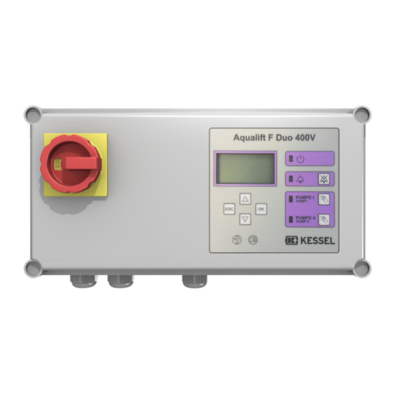
Abb. zeigt:
Schaltgerät
Aqualift F Duo 400V
Einweisung
Datum
Ort
Produktvorteile
Für Mono- und Duoanlagen
lieferbar
Anwenderfreundlich
Menüführung im mehrzeiligen
Display
Mit Selbstdiagnosesystem SDS
und Erinnerungsfunktion für die
nächste Wartung
Anzeige der aktuellen Messwerte
Einfache Einstellung der
funktionsrelevanten Parameter
Betriebsstundenzähler
Optionale Weiterleitung von Alarm-
und Sammelstörmeldungen über
GSM-Schnittstelle
Stempel Fachbetrieb
Seite 5
D
Page 29
GB
Page 55
F
Pagina 81
I
Pagina 107
NL
Strona 133
PL
Sach-Nr. 010-532
Advertisement
Chapters
Table of Contents

Related Manuals for Kessel Aqualift F Comfort 400V Series


Summary of Contents for Kessel Aqualift F Comfort 400V Series
- Page 1 ANLEITUNG FÜR EINBAU, BEDIENUNG UND WARTUNG Seite 5 Page 29 KESSEL - Schaltgerät Page 55 Aqualift F Comfort 400V Pagina 81 Pagina 107 Strona 133 Produktvorteile Für Mono- und Duoanlagen lieferbar Anwenderfreundlich Menüführung im mehrzeiligen Display Mit Selbstdiagnosesystem SDS Abb. zeigt: und Erinnerungsfunktion für die...
- Page 2 2 / 160 V 1.3...
- Page 3 Schaltgerät - ANTLEITUNG FÜR EINBAU, BEDIENUNG UND WARTUNG Original control unit - MANUAL FOR INSTALLATION, OPERATION AND MAINTENANCE Translation of the German original operating manual Gestionnaire - INSTRUCTIONS POUR LE MONTAGE, L‘UTILISATION ET LA MAINTENANCE Traduction des instructions de service originales allemandes Quadro elettrico - ISTRUZIONI PER MONTAGGIO, COMANDO E MANUTENZIONE Traduzione delle istruzioni dell’uso originali tedesche Schakelapparaat - HANDLEIDING VOOR INBOUW, BEDIENING EN ONDERHOUD...
- Page 4 4 / 160 V 1.3...
-
Page 5: Table Of Contents
Inhaltsverzeichnis Allgemeines Einleitung und Begrüßung ........7 Produktbeschreibung, allgemein . - Page 6 Optionen (Nachrüstungen) ........20 Wartung Wartungstermin einstellen .
-
Page 7: Allgemeines
1 Allgemeines Einleitung und Begrüßung 1 Allgemeines Sehr geehrte Kundin sehr geehrter Kunde, wir freuen uns, dass Sie sich für den Erwerb eines unserer Produkte entschieden haben. Sicher wird dieses Ihre Anforderungen in vollem Umfang erfüllen. Wir wünschen ihnen einen reibungslosen und erfolgreichen Einbau. -
Page 8: Typenschild
1 Allgemeines 1.2.2 Typenschild Informationen auf dem Typenschild Bezeichnung des Schaltgerätes Material- Nummer des Schaltgerätes Anschlussspannung und Anschlussfrequenz Stromaufnahmebereich Schutzart (IP) Seriennummer Gefahrenzeichen (elektr. Schaltgerät) Schutzklasse I - Schutzerdung Problemstoff Elektrogerät 10 Revisionsstand der Hardware 25 ATEX - Kennzeichnung (Optional) 28 CE-Zeichen Lieferumfang 11 Schaltgerät... -
Page 9: Baugruppen Und Funktionselemente
1 Allgemeines Baugruppen und Funktionselemente 13 Typenschild 14 Hauptschalter 15 Kabeldurchführungen, Anschlüsse 16 Display und Bedienfeld 1.5.1 Display und Bedienfeld, Anzeigen Navigationstasten für das Menü Pumpe 1 20* LED Pumpe 2 Alarm Betriebsbereit Pfeil oben Blättern im Menü Pfeil unten Blättern im Menü... -
Page 10: Sicherheit
2 Sicherheit Bestimmungsgemäße Verwendung 2 Sicherheit Das Schaltgerät Aqualift ist ausschließlich für die Steuerung von Hebeanlagen (DIN EN 12056) und Pumpstationen für fäkalienfreies und fäkalienhaltiges Abwasser zu verwenden. Ein Einsatz des Schaltgeräts in explosionsgefährdeter Umgebung ist unzulässig. Je nach Ausführung (siehe 1.2.1) ist der Anschluss von Schwimmerschaltern vorgesehen, die der ATEX- Richtlinie (94/9/EG:1994-03-23) entsprechen. -
Page 11: Explosionsgefahr
2 Sicherheit 2.4.2 Explosionsgefahr Bei Aufstellung von Aggregaten in explosionsgefährdeten Bereichen sind die Bestimmungen der Richtlinie 94/9/EG zu beachten. „ATEX-Baugruppen“ sind mit diesen Symbol gekennzeichnet: 11 / 160 V 1.3... -
Page 12: Montage
3 Montage 3 Montage Schaltgerät montieren Das Schaltgerät kann nur geöffnet werden, wenn sich der Hauptschalter <14> in Position OFF befindet. • Hauptschalter <14> in Position OFF bringen, und das Gehäuse aufklappen. • Gehäuse am vorgesehenen Ort montieren, dazu alle vier Befestigungsmöglichkeiten in den Ecken verwenden. -
Page 13: Niveaugeber Anschließen
3 Montage Niveaugeber anschließen 3.3.1 Drucksensor (Option) Soll ein Drucksensor zur Ermittlung des Pegelstandes verwendet werden, diesen wie folgt anschließen. • Druckleitung des Drucksensors auf den Anschlussnippel des Druckleitungsanschlusses <17> schieben und mit der Klemmmutter befestigen. • Ggf. Anschluss für einen Kompressor in die Druckleitung einbinden. -
Page 14: Erstinbetriebnahme
3 Montage Erstinbetriebnahme Ein Trockenlauf der Pumpe(n) ist unbedingt zu vermeiden. Tipp: Befüllen Sie den Abwasserbehälter vor dem Herstellen der Netzspannung so weit mit Wasser, dass im Fall eines unbeabsichtigten Einschaltens der Pumpe(n) (z.B. fehlerhafter Anschluss eines Niveausensors) diese nicht trocken laufen können. -
Page 15: Funktionskontrolle
3 Montage Leistungsgröße Sicherstellen, dass der auf dem Typenschild ausgewiesene Stromaufnahmebereich nicht überschritten wird. Das Schaltgerät würde im Betrieb eine Fehlermeldung ausgeben. • OK betätigen • Art der angeschlossene(n) Pumpe(n) mit den Pfeiltasten auswählen und mit OK bestätigen, das Menü 0 Systeminfo wird angezeigt - das Schaltgerät ist betriebsbereit. -
Page 16: Einstellungen, Menü
3 Montage 2. Überprüfung des Alarmschalters • Abwasserbehälter wie unter 1. Überprüfung der Pumpe(n) beschrieben befüllen, jedoch den Pegelstand so über die Markierung hinaus ansteigen lassen, dass am Schaltgerät Alarm ausgelöst wird (Signalton ertönt / Alarm-LED blinkt). • Wasserzufuhr abstellen. •... - Page 17 3 Montage Navigation im Menü Aktion Bedienung Menüpunkt auswählen Pfeil oben / Pfeil unten, ausgewählter Menüpunkt wird invertiert dargestellt Menüpunkt zur Bearbeitung OK. ist ein Menü-Unterpunkt vorhanden, wird dieser invertiert aktivieren dargestellt. Einstellwert anzeigen bearbeiten OK, Wert wird angezeigt bzw. zur Einstellung invertiert dargestellt Menü...
-
Page 18: Betrieb
4 Betrieb Einschalten 4 Betrieb • Hauptschalter <14> in Position I (ON) drehen, nach erfolgreichem Systemtest erscheint im Display <23> das Menü 0 Systeminfo und die grüne LED <22> leuchtet, das Schaltgerät Aqualift ist betriebsbereit. Alarm Quittieren [12] Ist ein Zustand aufgetreten, der einen Alarm auslöste (z.B. Fehler an einer Pumpe, Pegelstand des Abwassers erreichte Alarm-Niveau) leuchtet die Alarm-LED <21>. -
Page 19: Technische Daten
5 Technische Daten MONO kW DUO kW Nennleistung der Hebeanlage gem. Kessel Programmübersicht Nennstrom (in Betrieb) A 2x 3,2 2x 5,4 Stromaufnahmebereich, A 2,5 - 4 4 - 6,3 2x 2,5 - 4 2x 4 - 6,3 Maximale Schaltleistung, kW, cosφ =1... -
Page 20: Optionen (Nachrüstungen)
5 Technische Daten Die Anforderungen der Normen EN 50014:1997 + A1-A2, EN 50020:2002 werden erfüllt. EG-Baumusterprüfbescheinigung der Zenerbarrieren Kennzeichnung Typ Einzelanlage Typ Doppelanlage Niveaustromkreis in Zündschutzart Eigensicherheit EEx ia IIC Klemmen AUS, EIN, ALARM AUS, EIN1, EIN2, ALARM Zenerbarriere MTL 7789+, Höchstwerte: 15,8* / 28 V 28 V 93 mA... -
Page 21: Wartung
6 Wartung Notiz: Das Schaltgerät ist wartungsfrei 6 Wartung Wartungstermin einstellen Der Wartungstermin wird über das Menü 2, Punkt 2.3 eingestellt. Folgen Sie dem Bildschirmdialog (siehe auch 3.5, Einstellungen, Menü). Fehlersuche Anzeigetext Mögliche Ursache Abhilfemaßnahme Batteriefehler Batterie fehlt, ist defekt oder Spannung kleiner Batterieanschluss prüfen, ggf. -
Page 22: Anhang
7 Anhang 7 Anhang Menüstruktur Die Nummer <24> der jeweiligen Menüebene wird in Ziffernform in der obersten Displayzeile dargestellt. [13] Systeminfo Taste OK betätigen, um in die Ebenen 1 bis 3 zu gelangen Informationen 1.1 Betriebsstunden 1.1.1 Gesamtlaufzeit 1.1.2 Laufzeit Pumpe 1 1.1.3 Laufzeit Pumpe 2 1.1.4... - Page 23 7 Anhang 1.6 Parameter 1.6.1 Netz-Ein-Verzög 1.6.2 Höhe Stauglocke 1.6.3 Einschaltsperre 1.6.4 Messbereich 1.6.5 EIN1-Niveau 1.6.6 EIN2-Niveau 1.6.7 AUS1-Niveau 1.6.8 Alarm-Niveau 1.6.9 Ein-Verzögerung 1.6.10 Nachlaufzeit 1.6.11 Pumpenmodus 1.6.12 Grenzlaufzeit 1.6.13 Grenzlaufzahl 1.6.14 min. Strom 1.6.15 max. Strom 1.6.16 LEP-Offset 1.6.17 auto SDS Wartung 2.1 Handbetrieb...
- Page 24 7 Anhang 3.4.6 Pegelsonde 3.4.7 Pegelsonde + Alarm 3.4.8 Membranschalter 3.5 Kommunikation 3.5.1 Stationsname 3.5.2 Eigene Nr. 3.5.3 Modemtyp 3.5.4 3.5.5 SMS-Zentrale 3.5.6 SMS-Ziel 1 3.5.7 SMS-Ziel 2 3.5.8 SMS-Ziel 3 3.5.9 Status 3.6 Leistungsgrösse 3.6.1 Hebeanlage 1,1kW 3.6.2 Hebeanlage 2,2kW 3.6.3 Pumpstation 1,3kW 3.6.4...
-
Page 25: Anschlusspläne Schwimmerschalter Und Drucksensoren
7 Anhang Anschlusspläne Schwimmerschalter und Drucksensoren Die in den nachstehenden Darstellungen der Funktionsschematas verwendeten Bezeichnungen sind auf dem Anschlussplan gleichlautend verwendet. Der Anschlussplan für die Schwimmerschalter befindet sich im Gehäusedeckel des Schaltgeräts. 7.2.1 Aqualift F Mono 400 V Die Leitungsenden der Schwimmerschalter an den gleichlautenden Klemmen des Klemmenblocks anschließen (Siehe Bezeichnung in Abb. -
Page 26: Aqualift F Duo 400 V
7 Anhang 7.2.3 Aqualift F Duo 400 V Die Leitungsenden der Schwimmerschalter an den gleichlautenden Klemmen des Klemmenblocks anschließen (Siehe Bezeichnung in Abb. [16] ) Bezeichnung Alarm A = Beide Pumpen ausgeschaltet B = Pumpe 1 einschalten C = Pumpe 2 einschalten Ein2 D = Alarm* * bei steigendem Abwasserpegel... - Page 27 V 1.3...
- Page 29 Führend in Entwässerung Privater Wohnungsbau ohne Kanalanbindung 1 2 3 4 1 2 3 4 Öffentlicher Bau z.B. Krankenhaus Öffentlicher Bau z.B. Freizeitanlagen 1 2 3 4 Gewerblicher Bau z.B. Hotel Gewerblicher Bau z.B. Industriebau 2 3 5 Gewerblicher Bau z.B.
- Page 30 MANUAL FOR INSTALLATION, OPERATION AND MAINTENANCE Kessel – Aqualift F Comfort 400V Control Unit Product advantages Available for Mono and Duo stations User-friendly Menu navigation with multi-line display With SDS self-diagnosis system and reminder function for the next Figure shows:...
- Page 31 Table of contents General Introduction and welcome ........32 Product description, general .
- Page 32 Options (retrofits) ..........45 Maintenance Setting the maintenance date .
-
Page 33: General
1 General 1 General Introduction and welcome Dear Customer, We are delighted that you have decided to purchase one of our products. It is sure to satisfy your requirements to the full. We wish you a problem-free and successful installation. In our efforts to maintain our quality standard at the highest possible level, we are naturally dependent on your support. -
Page 34: Type Plate
1 General 1.2.2 Type plate Information on the type plate Designation of the control unit Material number of the control unit Connection voltage and frequency Power usage range Protection degree (IP) Serial number Risk symbols (electr. control unit) Protection class I – Protective earthing Problem material, electric device 10 Revision status of the hardware 25 ATEX mark (optional) -
Page 35: Assemblies And Functional Elements
1 General Assemblies and functional elements 13 Type plate 14 Main switch 15 Cable apertures, connections 16 Display and control panel 1.5.1 Display and control panel, displays Navigation keys for the menu Pump 1 20* LED Pump 2 Alarm Ready for operation Up arrow Scroll in the menu Down arrow... -
Page 36: Safety
2 Safety Proper use 2 Safety The Aqualift control unit may be used exclusively for controlling lifting stations (DIN EN 12056) and pumping stations for wastewater with and without sewage. Any use of the control unit in an environment at risk from explosions is not permissible. Depending on the version (see 1.2.1), it is possible to connect float switches that comply with the ATEX Directive (94/9/EC:1994-03-23). -
Page 37: Danger Of Explosion
2 Safety 2.4.2 Danger of explosion The deployment of units in areas at risk from explosions must be conducted in accordance with Directive 94/9/EC. “ATEX assemblies” are designated with this symbol: 36 / 160 V 1.3... -
Page 38: Assembly
3 Assembly Assembling the control unit 3 Assembly The control unit can be opened only when the main switch <14> is in the OFF position. • Turn the main switch <14> to the OFF position, and fold the housing open. •... -
Page 39: Connecting The Level Detector
3 Assembly Connecting the level detector 3.3.1 Pressure sensor (option) If it is planned to use a pressure sensor to determine the current level, connect the sensor as follows: • Push the pressure pipe of the pressure sensor onto the connection nipple of the pressure-pipe connection <17>... -
Page 40: Performing Initialization
3 Assembly Connecting the battery Connect the battery plug <74>. Connecting the mains voltage Supply the control unit with mains voltage; the initialization will then begin. While the LEDs light up for approx. 4 seconds, the electrical components are checked, the battery for the power outage message is activated and the 0.1. -
Page 41: Function Check
3 Assembly Performance size Make sure that the power usage range displayed on the type plate is not exceeded. Otherwise, the control unit would issue an error message in operating mode. • Press OK • Select the type of the connected pump(s) with the arrow keys and confirm with OK; the 0 System info menu is displayed –... -
Page 42: Settings, Menu
3 Assembly 2. Check of the alarm switch • Fill the wastewater container as described under 1. Check of the pump(s), but allow the level to climb above the marking so that an alarm is triggered on the control unit (audible alarm is sounded/alarm LED flashes). •... - Page 43 3 Assembly Navigation in the menu Action Operation Select menu item Up arrow/down arrow, selected menu item is shown in inverted format. Activate menu item for processing OK. If a menu sub-item is available, it will be displayed in inverted format.
-
Page 44: Operating Mode
4 Operating mode 4 Operating mode Switching on • Turn the main switch <14> to the position I (ON); after a successful system test, the display <23> shows the 0 System info menu and the green LED <22> lights up; the Aqualift control unit is now ready for operation. -
Page 45: Technical Data
5 Technical data 5 Technical data MONO kW DUO kW Rated power of the lifting station according to the Kessel product range overview Rated current (in operating mode) A 2x 3.2 2x 5.4 Power usage range, A 2.5 - 4 4 - 6.3... -
Page 46: Options (Retrofits)
5 Technical data The requirements of standards EN 50014:1997 + A1-A2, EN 50020:2002 will be fulfilled. EC-type examination certificate for Zener barriers Designation Single system type Dual system type Standard circuit In ignition protection class “Intrinsic safety”, EEx ia IIC T erminals OFF, ON, ALARM OFF, ON1, ON2, ALARM... -
Page 47: Maintenance
6 Maintenance Note: The control unit is maintenance-free 6 Maintenance Setting the maintenance date The maintenance date is set using menu 2, Item 2.3. Follow the dialogue on the screen (see also3.5, Settings, menu). Troubleshooting Display text Possible cause Remedial action Battery error Battery is missing, is faulty or voltage is less Check battery connection and replace battery, if... -
Page 48: Appendix
7 Appendix 7 Appendix Menu structure The number <24> of the respective menu level is displayed in numerical form in the top line of the display. [13] System info Actuate the OK key to move to levels 1 to 3 Information 1.1 Operation hours 1.1.1... - Page 49 7 Appendix 1.6 Parameters 1.6.1 Power-up delay 1.6.2 Sensor height 1.6.3 Start-up lock 1.6.4 Sensing zone 1.6.5 ON1 level 1.6.6 ON2 level 1.6.7 OFF1 level 1.6.8 Alarm level 1.6.9 On delay 1.6.10 Post run time 1.6.11 Pump mode 1.6.12 Max. run time 1.6.13 Max.
- Page 50 7 Appendix 3.4.6 Level sensor 3.4.7 Lev. sens.+alarm 3.4.8 Membrane switch 3.5 Communication 3.5.1 Plant name 3.5.2 Own number 3.5.3 Modem type 3.5.4 3.5.5 SMS-Center 3.5.6 SMS-Destination1 3.5.7 SMS-Destination2 3.5.8 SMS-Destination3 3.5.9 Status 3.6 Performance size 3.6.1 Lift. st. 1.1kW 3.6.2 Lift.
-
Page 51: Connection Plans For Float Switches And Pressure Sensors
7 Appendix Connection plans for float switches and pressure sensors The designations used in the following illustrations of the function diagrams are identical to the ones used in the connection plan. The connection plan for the float switches is located in the housing cover of the control unit. - Page 52 7 Appendix 7.2.3 Aqualift F Duo 400 V Connect the cable ends of the float switches to the identical terminals in the terminal block (see designation in Fig. [16] ) Designation Alarm A = Both pumps switched off B = Switch on pump 1 C = Switch on pump 2 D = Alarm* * Given rising wastewater level...
- Page 53 V 1.3...
- Page 54 V 1.3...
- Page 55 Leading in Drainage Private homes without public sewage connection 1 2 3 4 1 2 3 4 Public buildings (e.g. hospital) Public buildings (e.g. leisure facility) 1 2 3 4 Commercial buildings (e.g. hotel) Commercial buildings (e.g. industrial / manu- facturing facilities) 2 3 5 Commercial buildings...
- Page 56 INSTRUCTIONS POUR LE MONTAGE, L‘UTILISATION ET LA MAINTENANCE Gestionnaire de Kessel Aqualift F Comfort 400 V Avantages produit Disponible pour les installations mono et duo Facile à utiliser Guidage à travers le menu sur un écran à plusieurs lignes Avec système d‘autodiagnostic Sur la fig.
- Page 57 Sommaire Généralités Introduction et bienvenue ......... 58 Description générale du produit .
- Page 58 Options (postmontage) ......... . . 71 Maintenance Réglage de la date de maintenance .
-
Page 59: Généralités
1 Généralités Introduction et bienvenue 1 Généralités Chère cliente, cher client, Nous nous réjouissons de votre décision d‘acheter un de nos produits qui, nous en sommes certains, répondra totalement à vos attentes. Nous vous souhaitons un montage sans problème et plein de succès. Dans l‘effort de maintenir nos standards de qualité... -
Page 60: Plaque Signalétique
1 Généralités 1.2.2 Plaque signalétique Informations sur la plaque signalétique Désignation du gestionnaire Numéro de matériau du gestionnaire Tension de raccordement et fréquence de raccordement Plage de consommation de courant Type de protection (IP) Numéro de série Signe d‘alarme (gestionnaire électr.) Classe de protection I - protection par mise à... -
Page 61: Composants Et Éléments De Fonction
1 Généralités Composants et éléments de fonction 13 Plaque signalétique 14 Commutateur principal 15 Passages de câbles, raccordements 16 Écran et tableau de commande 1.5.1 Écran et tableau de commande, affichages Touches de navigation pour le menu Pompe 1 20* DEL Pompe 2 Alarme Opérationnel... -
Page 62: Sécurité
2 Sécurité Utilisation conforme 2 Sécurité Le gestionnaire Aqualift doit être utilisé exclusivement pour la commande de postes de relevage (DIN EN 12056) et de stations de pompage pour eaux grises et eaux noires. L‘utilisation du gestionnaire dans un environnement à risque d‘explosion est interdite. En fonction du modèle (voir 1.2.1), le raccordement d‘interrupteurs à... -
Page 63: Risque D'explosion
2 Sécurité 2.4.2 Risque d‘explosion Lors de la mise en place de groupes dans des zones à risque d‘explosion, les dispositions de la directive 94/9/CE doivent être respectées. Les « composants ATEX » sont signalés par ce symbole : 62 / 160 V 1.3... -
Page 64: Montage
3 Montage Montage du gestionnaire 3 Montage Il est possible d‘ouvrir le gestionnaire uniquement lorsque le commutateur principal <14> se trouve en position OFF. • Amener le commutateur principal <14> en position OFF et ouvrir le boîtier. • Monter le boîtier à l‘endroit prévu, utiliser pour cela toutes les quatre possibilités de fixation situées dans les angles. -
Page 65: Raccordement Du Commutateur De Niveau
3 Montage Raccordement du commutateur de niveau 3.3.1 Capteur de pression (en option) Si vous souhaitez utiliser un capteur de pression pour déterminer le niveau d‘eau, le raccorder comme suit. • Pousser la conduite forcée du capteur de pression sur le nipple de raccord du branchement de la conduite forcée <17>... -
Page 66: Première Mise En Service
3 Montage Première mise en service Le fonctionnement à sec des/de la pompe(s) doit absolument être évité. Conseil : avant d‘établir l‘alimentation électrique, remplissez le réservoir d‘eaux usées avec de l‘eau jusqu‘à un niveau suffisant pour qu‘en cas de mise en marche involontaire des/de la pompe(s) (p. ex. un mauvais raccordement du capteur de niveau), celles-ci ne fonctionnent pas à... -
Page 67: Contrôle De Fonctionnement
3 Montage Puissance nomin. S‘assurer que la plage de consommation de courant indiquée sur la plaque signalétique n‘est pas dépassée. Le gestionnaire afficherait alors un message d‘erreur lors du fonctionnement. • Appuyer sur OK • Sélectionner le type de pompe(s) raccordée(s) à l‘aide des touches fléchées et valider avec OK, le menu 0 Info. -
Page 68: Réglages, Menu
3 Montage 2. Contrôle du commutateur d‘alarme • Remplir le réservoir d‘eaux usées comme décrit sous 1. Contrôle de/des pompe(s), mais faire monter le niveau d‘eau au-dessus du repère jusqu‘à ce que l‘alarme soit déclenchée au niveau du gestionnaire (signal sonore retentit/la DEL d‘alarme clignote). - Page 69 3 Montage Navigation dans le menu Action Commande Sélectionner un point de menu Flèche vers le haut/flèche vers le bas, le point de menu sélectionné est représenté blanc sur noir Activer le point de menu pour OK. Lorsqu‘un point de menu est disponible, celui-ci est représenté l‘éditer blanc sur noir.
-
Page 70: Marche
4 Marche 4 Marche Mise en marche • Tourner le commutateur principal <14> sur la position I (ON), après l‘essai système réussi, le menu 0 Info. système s‘affiche sur l‘écran <23> et la DEL verte <22> s‘allume, le gestionnaire Aqualift est opérationnel. Confirmation de l‘alarme [12] Lorsqu‘un état qui a déclenché... -
Page 71: Caractéristiques Techniques
5 Caractéristiques techniques MONO kW DUO kW Puissance nominale du poste de relevage conformément à la vue d‘ensemble du programme Kessel Courant nominal (en marche), A 2 x 3,2 2 x 5,4 Plage d‘exception pour le courant, A 2,5 - 4... -
Page 72: Options (Postmontage)
5 Caractéristiques techniques Les exigences de la norme européenne EN 50014:1997 + A1-A2, EN 50020:2002 sont remplies. Attestation d‘examen CE de type des barrières Zener Caractérisation dans le type de protection d‘allumage sécurité intrinsèque EEx ia IIC Bornes ARRÊT, MARCHE, ARRÊT, MARCHE1, ALARME MARCHE2, ALARME... -
Page 73: Maintenance
6 Maintenance Note : Le gestionnaire ne demande pas d‘entretien. 6 Maintenance Réglage de la date de maintenance La date de maintenance se règle à partir du menu 2, point 2.3. Suivez les indications du dialogue sur l‘écran (voir également 3.5, Réglages, menu). Aide au diagnostic Texte affiché... -
Page 74: Annexe
7 Annexe Structure du menu 7 Annexe Le numéro <24> du niveau de menu correspondant est affiché sous forme de chiffre dans la première ligne de l‘écran. [13] Info. système Appuyer sur la touche OK pour accéder aux niveaux 1 à 3 Informations 1.1 H. - Page 75 7 Annexe 1.6 Paramètres 1.6.1 Sect. marche tps 1.6.2 Haut.cloche ret. 1.6.3 Séc. mis marche 1.6.4 Plage de mesure 1.6.5 Niveau MARCHE1 1.6.6 Niveau MARCHE2 1.6.7 Niveau ARRÊT1 1.6.8 Niveau Alarme 1.6.9 Marche temporat. 1.6.10 T emps de marche 1.6.11 Mode des pompes 1.6.12 Durée lim.marche...
- Page 76 7 Annexe 3.4.6 Sonde de niveau 3.4.7 Sonde niv.+Alarm 3.4.8 Interr. à membr. 3.5 Communication 3.5.1 Nom de unité 3.5.2 Son numéro 3.5.3 Type de modem 3.5.4 3.5.5 Centrale de SMS 3.5.6 SMS-Destinat. 1 3.5.7 SMS-Destinat. 2 3.5.8 SMS-Destinat. 3 3.5.9 Statut 3.6 Puissance nomin.
-
Page 77: Plans De Connexion Des Interrupteurs À Flotteur Et Des Capteurs De Pression
7 Annexe Plans de connexion des interrupteurs à flotteur et des capteurs de pression Les désignations utilisées dans les illustrations suivantes des schémas de fonctionnement sont utilisées de façon identique dans le plan de connexion. Le plan de connexion pour les interrupteurs à flotteur se trouve dans le couvercle du boîtier du gestionnaire. -
Page 78: Aqualift F Duo 400 V
7 Annexe 7.2.3 Aqualift F Duo 400 V Raccorder les extrémités des fils de sortie des interrupteurs à flotteur aux bornes du même nom du bloc de serrage (voir la désignation à la fig. [16]) Désignation alarme A = les deux pompes mises hors marche B = mettre la pompe 1 en marche* marche2... - Page 79 V 1.3...
- Page 80 V 1.3...
- Page 81 Leader en solution d’assainissement Construction de logements privés sans raccordement au réseau d’assainissement public 1 2 3 4 1 2 3 4 Construction de logements Construction publique, par privés sans raccordement au exemple aménagement de loisirs réseau d’assainissement public 1 2 3 4 Construction industrielle 2 3 5...
- Page 82 ISTRUZIONI PER MONTAGGIO, COMANDO E MANUTENZIONE Quadro elettrico Kessel Aqualift F Comfort 400 V Vantaggi prodotto Disponibile per impianti Mono e Duo Facile da usare Guida a menu con display multirighe Con sistema di autodiagnosi SDS e funzione reminder per manutenzione...
- Page 83 Sommario Informazioni generali Introduzione e saluti..........84 Descrizione del prodotto, generale .
- Page 84 Opzioni (installazioni successive) ....... . 97 Manutenzione Impostazione data manutenzione ....... . 98 Ricerca errori .
-
Page 85: Informazioni Generali
1 Informazioni generali Introduzione e saluti 1 Informazioni generali Gentile Signora, Gentile Signore, siamo lieti che abbia deciso di acquistare uno dei nostri prodotti che sicuramente soddisferà a pieno le sue esigenze. Le auguriamo un‘installazione corretta e di successo. Nello sforzo di mantenere il nostro standard di qualità al massimo livello, siamo naturalmente aperti anche al suo contributo. -
Page 86: Targhetta
1 Informazioni generali 1.2.2 Targhetta Informazioni sulla targhetta Denominazione del quadro elettrico Codice materiale del quadro elettrico Tensione e frequenza di allacciamento Range corrente assorbita Grado di protezione (IP) Numero di serie Segnale di pericolo (quadro elettrico) Classe di protezione I - messa a terra di protezione Materiali pericolosi strumento elettrico 10 Stato di revisione hardware 25 Marcatura ATEX (opzionale) -
Page 87: Gruppi Ed Elementi Funzionali
1 Informazioni generali Gruppi ed elementi funzionali 13 Targhetta 14 Comando principale 15 Passacavi, allacciamenti 16 Display e pannello di controllo 1.5.1 Display e pannello di controllo, visualizzazioni Tasti di navigazione per il menu Pompa 1 20* LED Pompa 2 Allarme Pronto all‘uso Freccia in alto... -
Page 88: Sicurezza
2 Sicurezza Destinazione d‘uso 2 Sicurezza Il quadro elettrico Aqualift deve essere utilizzato esclusivamente per il comando delle stazioni di sollevamento (DIN EN 12056) e le stazioni di pompaggio per acque reflue con e senza sostanze fecali. Non è consentito utilizzare il quadro elettrico in ambienti a rischio di esplosione. In base al modello (vedere 1.2.1) è... -
Page 89: Pericolo Di Esplosione
2 Sicurezza 2.4.2 Pericolo di esplosione Per l‘installazione di gruppi in aree a rischio di esplosione, attenersi alle disposizioni della direttiva 94/9/CE. I „moduli ATEX“ sono contrassegnati dal seguente simbolo: 88 / 160 V 1.3... -
Page 90: Montaggio
3 Montaggio 3 Montaggio Montaggio del quadro elettrico Il quadro elettrico può essere aperto solo se il comando principale <14> si trova su OFF. • Portare il comando principale <14> su OFF per aprire l‘alloggiamento. • Montare l‘alloggiamento sul luogo previsto, utilizzando tutte le quattro possibilità di fissaggio agli angoli. La fornitura contiene una maschera di foratura. -
Page 91: Collegamento Dell'indicatore Di Livello
3 Montaggio Collegamento dell‘indicatore di livello 3.3.1 Sensore a pressione (opzione) Se si deve utilizzare un sensore a pressione per la determinazione del livello, collegarlo come segue. • Spingere la linea di pressione del sensore a pressione sul nipplo di raccordo del collegamento della linea di pressione <17>... -
Page 92: Esecuzione Dell'inizializzazione
3 Montaggio Collegamento della batteria Inserire il connettore <74> della batteria. Produzione di tensione di rete Alimentare il quadro elettrico con tensione di rete, l‘inizializzazione comincia. Per circa 4 secondi i LED si accendono, e i componenti elettrici vengono controllati, la batteria per il messaggio di Caduta alimenta viene attivata e il menu 0.1. -
Page 93: Controllo Funzionale
3 Montaggio Dimensioni delle prestazioni Accertarsi che il range corrente assorbita indicato sulla targhetta non venga superato. Il quadro elettrico emetterebbe un messaggio di errore durante l‘attività. • Premere OK • Selezionare il tipo di pompa/e collegata/e con i tasti freccia e confermare con OK; viene visualizzato il menu 0 Inform.sistema - il quadro elettrico è... -
Page 94: Impostazioni, Menu
3 Montaggio 2. Controllo del comando dell‘allarme • Riempire il serbatoio per le acque reflue come descritto al punto 1. Controllo della/e pompa(e), tuttavia fare aumentare il livello sopra la marcatura in modo che sul quadro elettrico venga emesso un allarme (si sente un segnale acustico / il LED dell‘allarme lampeggia). - Page 95 3 Montaggio Navigazione nel menu Azione Comando Selezione della voce di menu Freccia in alto / in basso, la voce di menu selezionata viene visualizzata in modo inverso Attivazione della voce di menu OK. Se è presente una sottovoce del menu, questa viene visualizzata per l‘elaborazione in modo inverso.
-
Page 96: Attività
4 Attività Accensione 4 Attività • Ruotare il comando principale <14> nella posizione I (ON); al termine del test del sistema viene visualizzato sul display <23> il menu 0 Inform.sistema e il LED verde <22> si accende, il quadro elettrico Aqualift è pronto all‘uso. Confermare allarme acustico [12] Se si è... -
Page 97: Dati Tecnici
5 Dati tecnici 5 Dati tecnici MONO kW DUO kW Potenza nominale della stazione di sollevamento secondo panoramica del programma Kessel Corrente nominale (in attività) A 2x 3,2 2x 5,4 Range corrente assorbita, A 2,5 - 4 4 - 6,3... -
Page 98: Opzioni (Installazioni Successive)
5 Dati tecnici I requisiti delle norme EN 50014:1997 + A1-A2 e EN 50020:2002 sono soddisfatti. Certificato della prova di omologazione Contrassegno delle barriere Zener nel tipo di protezione antincendio Sicurezza intrinseca EEx ia IIC morsetti OFF, ON, ALLARME OFF, ON1, ON2, ALLARME Barriera Zener MTL 7789+, Valori massimi: 15,8* / 28 V 28 V... -
Page 99: Manutenzione
6 Manutenzione Nota: La centralina di commutazione non richiede manutenzione 6 Manutenzione Impostazione data manutenzione La data manutenzione viene impostata dal menu 2, voce 2.3. Seguire il dialogo della schermata (vedere anche 3.5, Impostazioni, menu). Ricerca errori Testo visualizzato Possibile causa Rimedio Errore batteria Batteria assente, difettosa o tensione inferiore a... -
Page 100: Appendice
7 Appendice Struttura del menu 7 Appendice Il numero <24> del rispettivo livello di menu viene visualizzato in formato numerico nella riga superiore del display. [13] Inform.sistema Premere il tasto OK per accedere ai piani da 1 a 3 Informazioni Ore di funziona. - Page 101 7 Appendice Parametri 1.6.1 Rit. accens.rete 1.6.2 Alt. tubo rist. 1.6.3 Blocco accens. 1.6.4 Campo di misura 1.6.5 Livello ACCESO1 1.6.6 Livello ACCESO2 1.6.7 Livello SPENTO1 1.6.8 Livello allarme 1.6.9 Accensione rit. 1.6.10 Dur.fun.dopo sp. 1.6.11 Modalità pompa 1.6.12 Num max accensioni 1.6.13 Tempo max funzionamento 1.6.14...
- Page 102 7 Appendice 3.4.4 Pres.+Comp.+All. 3.4.5 Galleggiante 3.4.6 Sonda di livello 3.4.7 Sonda liv.+ all. 3.4.8 Comando a membr. Comunicazione 3.5.1 Nome stazione 3.5.2 Proprio numero 3.5.3 Tipo di modem 3.5.4 3.5.5 SMS centrale 3.5.6 SMS - arrivo 1 3.5.7 SMS - arrivo 2 3.5.8 SMS - arrivo 3 3.5.9...
-
Page 103: Schemi Di Collegamento Comandi A Galleggiante E Sensori A Pressione
7 Appendice Schemi di collegamento comandi a galleggiante e sensori a pressione Le denominazioni utilizzate nelle seguenti rappresentazioni degli schemi funzionali sono identiche a quelle utilizzate nello schema di collegamento. Lo schema di collegamento per i comandi a galleggiante si trova nel coperchio dell‘alloggiamento del quadro elettrico. - Page 104 7 Appendice 7.2.3 Aqualift F Duo 400 V Collegare le estremità delle linee dei comandi a galleggiante ai morsetti con la stessa denominazione nella morsettiera (vedere Denominazione nella fig. [16] ) Denominazione Allarme A = entrambe le pompe spente B = accendere pompa 1 C = accendere pompa 2 Acceso2 D = allarme*...
- Page 105 V 1.3...
- Page 106 V 1.3...
- Page 107 Leader del drenaggio Edilizia residenziale privata senza collegamento alla fogna 1 2 3 4 1 2 3 4 Edilizia pubblica per es. Ospedale Edilizia pubblica per es. Impianti ricreativi 1 2 3 4 Edilizia commerciale per es. Albergo Edilizia commerciale per es.
- Page 108 HANDLEIDING VOOR INBOUW, BEDIENING EN ONDERHOUD Kessel – schakelapparaat Aqualift F Comfort 400 V Productvoordelen Voor mono- en duo-installaties leverbaar Gebruiksvriendelijk Menu-interface in meerregelig display Met zelfdiagnosesysteem SDS Afb. toont: en herinneringsfunctie voor het schakelapparaat volgende onderhoud Aqualift F Mono...
- Page 109 Inhoudsopgave Algemeen Inleiding en begroeting........110 Productbeschrijving, algemeen .
- Page 110 Opties (uitbreidingen)......... 123 Onderhoud Onderhoudstermijn instellen .
-
Page 111: Algemeen
1 Algemeen Inleiding en begroeting 1 Algemeen Geachte klant We zijn verheugd dat u beslist hebt een van onze producten te kopen. Het product zal met zekerheid volledig aan uw eisen voldoen. We wensen u een probleemloze en succesvolle inbouw. In ons streven om onze kwaliteitsstandaard op het hoogst mogelijke niveau te houden, zijn we natuurlijk ook op uw medewerking aangewezen. -
Page 112: Typeplaatje
1 Algemeen 1.2.2 Typeplaatje Informatie op het typeplaatje Benaming van het schakelapparaat Materiaalnummer van het schakelapparaat Aansluitspanning en aansluitfrequentie Stroomverbruik Beschermingsklasse (IP) Serienummer Gevarentekens (elektr. schakelapparaat) Beschermingsklasse I - randaarding Probleemstof elektrisch apparaat 10 Revisiestand van de hardware 25 ATEX-aanduiding (optioneel) 28 CE-teken Leveringsomvang 11 Schakelapparaat... -
Page 113: Bouwgroepen En Functie-Elementen
1 Algemeen Bouwgroepen en functie-elementen 13 Typeplaatje 14 Hoofdschakelaar 15 Kabeldoorvoeren, aansluitingen 16 Display en bedieningsveld 1.5.1 Display en bedieningsveld, indicaties Navigatietoetsen voor het menu Pomp 1 20* LED Pomp 2 Alarm Bedrijfsklaar Pijl omhoog Bladeren in het menu Pijl omlaag Bladeren in het menu Wissen van een invoer, terug Alarm... -
Page 114: Veiligheid
2 Veiligheid 2 Veiligheid Reglementair gebruik Het schakelapparaat Aqualift mag uitsluitend voor de besturing van pompinstallaties (DIN EN 12056) en pompstations voor fecaliënvrij en fecaliënhoudend afvalwater gebruikt worden. Het gebruik van het schakelapparaat in een explosieve omgeving is niet toegestaan. Afhankelijk van de uitvoering (zie 1.2.1) is aansluiting van vlotterschakelaars vereist, die aan de ATEX-richtlijn (94/9/EG:1994-03-23) voldoen. -
Page 115: Explosiegevaar
2 Veiligheid 2.4.2 Explosiegevaar Bij de opstelling van aggregaten in explosieve zones moeten de bepalingen van de richtlijn 94/ 9/EG in acht genomen worden. „ATEX-bouwgroepen“ zijn met dit symbool aangeduid: 114 / 160 V 1.3... -
Page 116: Montage
3 Montage Schakelapparaat monteren 3 Montage Het schakelapparaat kan alleen geopend worden als de hoofdschakelaar <14> zich in de positie OFF bevindt. • Hoofdschakelaar <14> in positie OFF brengen en de behuizing openklappen. • Behuizing aan de gewenste plaats monteren, hiervoor de vier bevestigingsmogelijkheden in de hoeken gebruiken. -
Page 117: Aqualift F Mono 400V
3 Montage Niveaugever aansluiten 3.3.1 Druksensor (optie) Moet een druksensor voor het bepalen van het peil gebruikt worden, dan moet deze als volgt aangesloten worden. • Drukleiding van de druksensor op de aansluitnippel van de drukleidingaansluiting <17> schuiven en met de klemmoer bevestigen. -
Page 118: Eerste Ingebruikneming
3 Montage Eerste ingebruikneming Het droog lopen van de pomp(en) moet absoluut vermeden worden. Tip: vul het afvalwaterreservoir voor het tot stand brengen van de netvoeding met zoveel water dat in het geval van het per ongeluk inschakelen van de pomp(en) (bijv. foute aansluiting van een niveausensor) deze niet droog kunnen lopen. Batterij aansluiten Stekker <74>... -
Page 119: Functiecontrole
3 Montage Capaciteitsgrootte Ervoor zorgen dat het op het typeplaatje vermelde stroomverbruik niet overschreden wordt. Het schakelapparaat zou tijdens een gebruik een foutmelding geven. • Op OK drukken • Soort van de aangesloten pomp(en) met de pijltoetsen selecteren en met OK bevestigen, het menu 0 Systeeminformat. -
Page 120: Instellingen, Menu
3 Montage 2. Controle van de alarmschakelaar • Afvalwaterreservoir zoals onder 1. Controle van de pomp(en) beschreven vullen, maar het peil zover boven de markering laten stijgen dat aan het schakelapparaat een alarm geactiveerd wordt (signaaltoon weerklinkt/ alarm-LED knippert). • Watertoevoer afsluiten. •... - Page 121 3 Montage Navigatie in het menu Actie Bediening Menupunt selecteren Pijl omhoog/pijl omlaag, geselecteerd menupunt wordt negatieve tekst weergegeven Menupunt voor de bewerking OK. Is er een menu-onderpunt voorhanden, dan wordt deze in activeren negatieve tekst weergegeven. Instelwaarde weergeven OK, waarde wordt weergegeven resp. voor de instelling in negatieve bewerken tekst weergegeven Menu verlaten...
-
Page 122: Bedrijf
4 Bedrijf 4 Bedrijf Inschakelen • Hoofdschakelaar <14> op positie I (ON) draaien, na succesvolle systeemtest verschijnt op het display <23> het menu 0 Systeeminformat. en de groene LED <22> brandt, het schakelapparaat Aqualift is bedrijfsklaar. Alarm bevestigen [12] Is er een toestand opgetreden die een alarm activeerde (bijv. fout aan een pomp, peil van het afvalwater bereikte alarmniveau), brandt de alarm-LED <21>. -
Page 123: Technische Gegevens
5 Technische gegevens 5 Technische gegevens MONO kW DUO kW Nominaal vermogen van de pompinstallatie volgens Kessel-programmaoverzicht Nominale stroom (in bedrijf) A 2x 3,2 2x 5,4 Stroomverbruikbereik, A 2,5 - 4 4 - 6,3 2x 2,5 - 4 2x 4 - 6,3 Maximaal schakelvermogen, kW, cosφ... -
Page 124: Opties (Uitbreidingen)
5 Technische gegevens De vereisten van de normen EN 50014:1997 + A1-A2, EN 50020:2002 worden vervuld. EG-proefmodelkeuringsrapport van de zenerbarrières Aanduiding in ontstekingsbeschermklasse eigenveiligheid EEx ia IIC Klemmen UIT, AAN, ALARM UIT, AAN1, AAN2, ALARM Zenerbarri7re MTL 7789+, maximumwaarden: 15,8* / 28 V 28 V 93 mA 300 Ù... -
Page 125: Onderhoud
6 Onderhoud Notitie: Het schakelapparaat is onderhoudsvrij 6 Onderhoud Onderhoudstermijn instellen De onderhoudstermijn wordt via het menu 2, punt 2.3 ingesteld. Volg de beeldschermdialoog (zie ook 3.5, Instellingen, menu). Foutopsporing Weergavetekst Mogelijke oorzaak Oplossing Batterijfout Batterij ontbreekt, is defect of spanning is kleiner Batterijaansluiting controleren, evt. -
Page 126: Bijlage
7 Bijlage 7 Bijlage Menustructuur Het nummer <24> van het betreffende menuniveau wordt in cijfervorm in de bovenste displayregel weergegeven. [13] Systeeminformat. Toets OK indrukken om naar de niveaus 1 tot 3 te gaan Informatie Bedrijfsuren 1.1.1 Totale looptijd 1.1.2 Looptijd pomp 1 1.1.3 Looptijd pomp 2... - Page 127 7 Bijlage Parameter 1.6.1 Inschvertr voed. 1.6.2 Sensorhoogte 1.6.3 Insch.vergr. 1.6.4 Meetbereik 1.6.5 AAN1-niveau 1.6.6 AAN2-niveau 1.6.7 UIT1-niveau 1.6.8 Alarm-niveau 1.6.9 Een-vertraging 1.6.10 Nalooptijd 1.6.11 Pompmodus 1.6.12 Max. insch.tijd 1.6.13 Max.insch.mom. 1.6.14 Min. stroom 1.6.15 Max. stroom 1.6.16 LEP-offset 1.6.17 auto SDS Onderhoud Handbediening...
- Page 128 7 Bijlage 3.4.5 Vlotter 3.4.6 Niveausensor 3.4.7 Niv.sens.+alarm 3.4.8 Membraanschak. Communicatie 3.5.1 Stationsnaam 3.5.2 Eigen nummer 3.5.3 Modemtype 3.5.4 3.5.5 SMS-centrale 3.5.6 SMS-doel 1 3.5.7 SMS-doel 2 3.5.8 SMS-doel 3 3.5.9 Status Capac.grootte 3.6.1 Pompinst. 1,1 kW 3.6.2 Pompinst. 2,2 kW 3.6.3 Pompstat.
-
Page 129: Aansluitschema's Vlotterschakelaar En Druksensoren
7 Bijlage Aansluitschema‘s vlotterschakelaar en druksensoren De in de volgende weergave van de functieschema‘s gebruikte benamingen zijn op het aansluitschema ook gebruikt. Het aansluitschema voor de vlotterschakelaars bevindt zich in het behuizingsdeksel van het schakelapparaat. 7.2.1 Aqualift F Mono 400 V De leidingeinden van de vlotterschakelaars aan de gelijkluidende klemmen van het klemmenblok aansluiten (zie benaming in afb. -
Page 130: Aqualift F Duo 400 V Atex
7 Bijlage 7.2.3 Aqualift F Duo 400 V De leidingeinden van de vlotterschakelaars aan de gelijkluidende klemmen van het klemmenblok aansluiten (zie benaming in afb. [16] ) Benaming Alarm A = beide pompen uitgeschakeld B = pomp 1 inschakelen C = pomp 2 inschakelen Aan1 D = alarm* * bij stijgend afvalwaterpeil... -
Page 131: Aansluitschema's
V 1.3... - Page 133 Toonaangevend in waterafvoertechniek Particuliere woningbouw zonder aansluiting op riool 1 2 3 4 1 2 3 4 Utiliteitsbouw bv. ziekenhuis Utiliteitsbouw bv. vrijetijdsvoorzieningen 1 2 3 4 Bedrijfsmatige bouw bv. hotel Bedrijfsmatige bouw bv. industriële bouw 2 3 5 Bedrijfsmatige bouw bv.
- Page 134 INSTRUKCJA ZABUDOWY, OBSŁUGI I KONSERWACJI Kessel – urządzenie sterownicze Aqualift F Comfort 400 V Zalety produktu W wersji przeznaczonej do instalacji pojedynczych i podwójnych Łatwa obsługa Nawigacja na wielowierszowym wyświetlaczu Rys. przedstawia: Z systemem autodiagnozy SDS oraz urządzenie funkcją przypomnienia o kolejnej...
- Page 135 Spis treści Informacje ogólne Wstęp i powitanie ..........136 Opis produktu, informacje ogólne .
- Page 136 Opcje (wyposażenie dodatkowe) ....... . 149 Konserwacja Ustawianie terminu konserwacji....... . . 150 Wyszukiwanie błędów .
-
Page 137: Informacje Ogólne
1 Informacje ogólne Wstęp i powitanie 1 Informacje ogólne Szanowni Klienci! Gratulujemy zakupu jednego z naszych produktów. Z pewnością spełni on wszystkie Państwa oczekiwania. Życzymy, by montaż przebiegł bez zakłóceń. Dążąc do utrzymania najwyższego poziomu jakości, korzystamy oczywiście także z Państwa pomocy. Będziemy wdzięczni za wszelkie sugestie dotyczące możliwości ulepszania naszych produktów. -
Page 138: Tabliczka Znamionowa
1 Informacje ogólne 1.2.2 Tabliczka znamionowa Informacje na tabliczce znamionowej Nazwa urządzenia sterowniczego Numer seryjny materiału urządzenia sterowniczego Napięcie przyłączeniowe i częstotliwość Zakres poboru prądu Rodzaj ochrony (IP) Numer seryjny Oznaczenia ostrzegawcze (elektr. urządzenie sterownicze) Klasa ochronności I – uziemienie ochronne Materiał... -
Page 139: Podzespoły I Elementy Funkcyjne
1 Informacje ogólne Podzespoły i elementy funkcyjne 13 Tabliczka znamionowa 14 Włącznik główny 15 Przepusty kablowe, przyłącza 16 Wyświetlacz i panel sterowniczy 1.5.1 Wyświetlacz i panel sterowniczy, komunikaty Przyciski nawigacyjne menu Pompa 1 20* LED Pompa 2 Alarm Urządzenie gotowe do pracy Strzałka w górę... -
Page 140: Bezpieczeństwo
2 Bezpieczeństwo Zastosowanie zgodne z przeznaczeniem 2 Bezpieczeń stwo Urządzenie sterownicze Aqualift przeznaczone jest wyłącznie do sterowania przepompowniami (DIN EN 12056) oraz przepompowniami do ścieków fekalnych i wolnych od fekaliów. Zastosowanie urządzenia sterowniczego w obszarze zagrożonym wybuchem jest niedozwolone. W zależności od wersji (patrz 1.2.1) przewidziane jest podłączenie przełączników pływakowych, zgodnych z dyrektywą... -
Page 141: Zagrożenia Związane Z Produktem
2 Bezpieczeństwo Zagrożenia związane z produktem 2.4.1 Zagrożenia związane z napięciem elektrycznym i przewodami Wszystkie przewodzące prąd elementy konstrukcyjne są zabezpieczone przed przypadkowym kontaktem. Przed otwarciem osłon obudowy, wtyczek i przewodów należy je odłączyć od zasilania. Prace na elektrycznych elementach konstrukcyjnych mogą być przeprowadzane wyłącznie przez personel specjalistyczny (patrz 2.2). -
Page 142: Montaż
3 Montaż 3 Montaż Montaż urządzenia sterowniczego Urządzenie sterownicze można otwierać tylko wtedy, gdy włącznik główny <14> znajduje się w pozycji OFF. • Należy umieścić włącznik główny <14> w pozycji OFF i otworzyć obudowę. • Należy zamontować urządzenie w wyznaczonym miejscu, wykorzystując do tego wszystkie cztery możliwości mocowania w narożnikach. -
Page 143: Podłączanie Czujnika Poziomu
3 Montaż Podłączanie czujnika poziomu 3.3.1 Czujnik ciśnienia (opcjonalnie) Jeśli do ustalania stanu wodowskazowego stosowany ma być czujnik ciśnienia, należy podłączyć go w następujący sposób. • Przewód ciśnieniowy czujnika ciśnienia należy dosunąć do złączki przyłącza przewodu ciśnieniowego <17> i przymocować nakrętką zaciskową. •... -
Page 144: Pierwsze Uruchomienie
3 Montaż Pierwsze uruchomienie Należy koniecznie unikać pracy pomp(y) przy niedoborze środków smarowych. Wskazówka: przed podłączeniem napięcia sieciowego należy napełnić zbiornik na ścieki wodą, aby w przypadku przypadkowego włączenia pomp(y) (np. nieprawidłowego podłączenia czujnika poziomu) nie doszło do pracy przy niedoborze środków smarowych. Podłączanie baterii Należy podłączyć... -
Page 145: Kontrola Funkcji
3 Montaż Współczynnik wydajności Należy upewnić się, że podany na tabliczce znamionowej zakres poboru prądu nie został przekroczony. W takim przypadku urządzenie sterownicze będzie sygnalizowało błąd działania. • Wcisnąć przycisk OK. • Za pomocą strzałek należy wybrać rodzaj podłączonej pompy (pomp) i potwierdzić przyciskiem OK, wyświetlone zostanie menu 0 Info systemowe –... -
Page 146: Ustawienia, Menu
3 Montaż 2. Kontrola przełącznika alarmowego • Należy napełnić zbiornik na ścieki w sposób przedstawiony w punkcie 1. Kontrola pomp(y), jednak stan wodowskazowy powinien znaleźć się na takiej wysokości ponad oznaczeniem, aby urządzenie sterownicze uruchomiło alarm (rozbrzmiewa sygnał dźwiękowy / pulsuje alarmowa dioda LED). •... - Page 147 3 Montaż Czynność Obsługa Wybrać punkt menu Strzałka w górę / strzałka w dół, wybrany punkt menu zostanie wyświetlony odwrotnie. Aktywowanie punktu menu do edycji OK. Jeśli dostępny jest punkt podmenu, zostanie on wyświetlony odwrotnie. Edycja wyświetlanych wartości OK, wartość zostanie wyświetlona bądź przedstawiona odwrotnie nastawczych względem ustawienia.
-
Page 148: Działanie
4 Działanie 4 Dzia łanie Włączanie • Włącznik główny <14> należy ustawić w pozycji I (ON), po pozytywnym zakończeniu testu systemowego na wyświetlaczu <23> ukaże się menu 0 Info systemowe oraz zaświeci się zielona dioda LED <22>, urządzenie sterownicze Aqualift jest gotowe do pracy. -
Page 149: Dane Techniczne
5 Dane techniczne 5 Dane techniczne MONO kW DUO kW Wydajność znamionowa przepompowni zgodnie z asortymentem firmy Kessel Prąd znamionowy (podczas działania) A 2x 3,2 2x 5,4 Zakres poboru prądu, A 2,5 - 4 4 - 6,3 2x 2,5–4 2x 4–6,3 Maksymalna obciążalność, kW, cosφ... -
Page 150: Opcje (Wyposażenie Dodatkowe)
5 Dane techniczne Wymagania norm EN 50014:1997 + A1-A2, EN 50020:2002 są spełnione. Certyfikat oceny typu WE barier Zenera Oznakowanie w rodzaju ochrony przeciwzapłonowej samobezpieczeństwo EEx ia IIC Zaciski WYŁ., WŁ., ALARM WYŁ., WŁ.1, WŁ.2, ALARM Bariera Zenera MTL 7789+, wartości maksymalne: 15,8* / 28 V 28 V... -
Page 151: Konserwacja
6 Konserwacja Uwaga: Urządzenie sterownicze nie wymaga konserwacji. 6 Konserwacja Ustawianie terminu konserwacji Termin konserwacji należy ustawić poprzez menu 2, punkt 2.3. Należy postępować zgodnie z oknami dialogowymi (patrz również 3.5, Ustawienia, menu). Wyszukiwanie błędów Tekst komunikatu Możliwa przyczyna Środki zaradcze Błąd baterii Brak baterii, bateria jest uszkodzona lub napięcie Należy sprawdzić... -
Page 152: Załącznik
7 Załącznik Struktura menu 7 Załącznik Numer <24> danego poziomu menu wyświetlany jest w formie cyfry w górnym wierszu wyświetlacza. [13] Info systemowe Wcisnąć przycisk OK, by przejść do poziomów 1–3 Informacje 1.1 Godziny pracy 1.1.1 Calkow.cz.pr. 1.1.2 Cz. pr. pompy 1 1.1.3 Cz. - Page 153 7 Załącznik 1.6 Parametry 1.6.1 Opóź.włącz.sieci 1.6.2 Wys.dzw.spiętrz. 1.6.3 Blokada włącz. 1.6.4 Zakres pomiarowy 1.6.5 Poziom WŁ.1 1.6.6 Poziom WŁ.2 1.6.7 Poziom WYŁ.1 1.6.8 Poziom alarm 1.6.9 Opóź. włącz. 1.6.10 Czas wybiegu 1.6.11 Tryb pompy 1.6.12 Maks. czas pracy 1.6.13 Maks.licz.cyk.p.
- Page 154 7 Załącznik 3.4.6 Sonda poziomu 3.4.7 Sonda poz.+alarm 3.4.8 Przeł. membran. 3.5 Komunikacja 3.5.1 Nazwa stacji 3.5.2 Nr własny 3.5.3 Typ modemu 3.5.4 3.5.5 Centrala SMS 3.5.6 SMS – cel 1 3.5.7 SMS – cel 2 3.5.8 SMS – cel 3 3.5.9 Status 3.6 Współcz.
-
Page 155: Schematy Połączeń, Przełącznik Pływakowy I Czujniki Ciśnienia
7 Załącznik Schematy połączeń, przełącznik pływakowy i czujniki ciśnienia Nazwy zastosowane na poniższych ilustracjach schematów funkcjonalnych odpowiadają tym zastosowanym na schemacie połączeń. Schemat połączeń przełącznika pływakowego znajduje się na pokrywie obudowy urządzenia sterowniczego. 7.2.1 Aqualift F Mono 400 V Należy podłączyć końcówki przewodów przełącznika pływakowego do zacisków bloku zaciskowego o tej samej nazwie (patrz nazwa na rys. -
Page 156: Aqualift F Duo 400 V
7 Załącznik 7.2.3 Aqualift F Duo 400 V Należy podłączyć końcówki przewodów przełącznika pływakowego do zacisków bloku zaciskowego o tej samej nazwie (patrz nazwa na rys. [16] ) Nazwa Alarm A = obie pompy wyłączone B = włącz pompę 1 C = włącz pompę... -
Page 157: Schematy Połączeń
V 1.3... - Page 158 V 1.3...
- Page 159 V 1.3 158 / 160...
- Page 160 Wiodący producent systemów odwadniania Budownictwo mieszkaniowe bez podłączenia do kanalizacji 1 2 3 4 5 1 2 3 4 5 Budynki użyteczności Budowle ogólnodostępne publicznej, np. szpitale np. obiekty rekreacyjne Działalność gospodarcza np. hotele Budownictwo przemysłowe 2 3 5 Budownictwo handlowo-usługowe np.
Need help?
Do you have a question about the Aqualift F Comfort 400V Series and is the answer not in the manual?
Questions and answers