Kessel Aqualift F Basic Installation And Operating Manual
Pumping station
Hide thumbs
Also See for Aqualift F Basic:
- Installation and operating manual (216 pages) ,
- Installation, operating and maintenance instructions (180 pages) ,
- Instructions for installation, operation and maintenance (180 pages)
Table of Contents
Advertisement
Available languages
Available languages
Quick Links
2019/12
Aqualift F Basic
Aqualift F Basic
DE
EN
FR
016-102_03 DE_EN_FR
Pumpstation / Einbau- und
Bedienungsanleitung.........................................2
Pumping station / Installation and operating
manual............................................................ 48
Poste de pompage / Instructions de pose et
d'utilisation...................................................... 94
Advertisement
Chapters
Table of Contents

Subscribe to Our Youtube Channel
Related Manuals for Kessel Aqualift F Basic


Summary of Contents for Kessel Aqualift F Basic
- Page 1 Aqualift F Basic Aqualift F Basic Pumpstation / Einbau- und Bedienungsanleitung.........2 Pumping station / Installation and operating manual............48 Poste de pompage / Instructions de pose et d’utilisation............94 2019/12 016-102_03 DE_EN_FR...
-
Page 2: Table Of Contents
Inhalt Liebe Kundin, lieber Kunde, als Premiumhersteller von innovativen Produkten für die Hinweise zu dieser Anleitung........Entwässerungstechnik bietet KESSEL ganzheitliche Sys- Sicherheit..............temlösungen und kundenorientierten Service. Dabei stel- Einleitung..............len wir höchste Qualitätsstandards und setzen konsequent auf Nachhaltigkeit - nicht nur bei der Herstellung unserer Technische Daten............ -
Page 3: Hinweise Zu Dieser Anleitung
Hinweise zu dieser Anleitung Sicherheit Folgende Darstellungskonventionen erleichtern die Orientie- Folgende Symbole werden verwendet: rung: Zeichen Bedeutung Darstellung Erläuterung Gerät freischalten! siehe Abbildung 1 Positionsnummer 5 von nebenstehender Abbildung Gebrauchsanweisung beachten Handlungsschritt in Abbildung CE-Kennzeichnung Prüfen, ob Hand- steuerung aktiviert Handlungsvoraussetzung wurde. - Page 4 Der Betreiber der Anlage ist dazu verpflichtet: eine Gefährdungsbeurteilung zu erstellen, entsprechende Gefährdungszonen zu ermitteln und aus- zuweisen, Sicherheitsunterweisungen durchzuführen, gegen die Benutzung durch Unbefugte zu sichern. Person freigegebene Tätigkeiten an KESSEL-Anlagen Betreiber Sichtprüfung, Inspek- tion, Batterietausch Sachkundiger, (kennt, ver- Entleerung, Reinigung steht Betriebsanweisung)
- Page 5 Person freigegebene Tätigkeiten an KESSEL-Anlagen Fachkundiger, (Fachhand- Einbau, Tausch, War- werker, nach Einbauanwei- tung von Komponen- sung und Ausführungsnormen) ten, Inbetriebnahme Elektrofachkraft VDE 0105 Arbeiten an elektri- (nach Vorschriften für elektr. scher Installation Sicherheit, oder nach natio- nalen Entsprechungen) 1) Bedienung und Montage darf nur durch Personen erfolgen, die das 18. Lebensjahr vollendet haben.
- Page 6 WARNUNG ACHTUNG Gefahr durch Überspannung! Kontaminierte Oberfläche! Anlage nur in Gebäuden betreiben, in denen ein Anlage und Umgebung können durch Keime verun- Überspannungsableiter (z. B. Überspannungs- reinigt sein. schutzeinrichtung Typ 2 nach VDE) installiert Keine Nahrungsmittel im selben Raum lagern ist.
-
Page 7: Einleitung
VORSICHT Einleitung Pumpen können unerwartet anlaufen. Vor Wartung oder Reparatur der Anlage ausschal- Bestimmungsgemäße Verwendung ten oder Stromversorgung abtrennen. Die Anlage darf nur zum Abpumpen von haushaltsüblichem Die Pumpe darf niemals trocken oder im Schlürf- fäkalienhaltigen Abwasser, nicht jedoch von brennbaren betrieb laufen, Laufrad und Pumpengehäuse bzw. - Page 8 Lieferumfang Mono Behälter mit Abdeckplatte Pumpe (im Karton) Armaturen (im Karton) Kleinteile mit Einbau- und Bedienungsanleitung (in Tüte) Palette 8 / 144 Pumpstation / Einbau- und Bedienungsanleitung 016-102_03 DE_EN_FR...
- Page 9 Mono Tronic / Duo Tronic Behälter mit Abdeckplatte Schaltgerät (im Karton) Kleinteile mit Einbau- und Bedienungsanleitung (in Tüte) Schwimmerhalterung (im Karton) Pumpe(n) (im Karton) Verrohrung(en) (im Karton) Palette 016-102_03 DE_EN_FR Pumpstation / Einbau- und Bedienungsanleitung 9 / 144...
- Page 10 Produktbeschreibung Die Anlage ist zum Einbau ins Erdreich, in den mitgelieferten Schacht, außerhalb von Gebäuden vorgesehen. Die Anlage wird für die Bestückung mit einer oder zwei Pumpen (Mono/ Duo) hergestellt. Der Aufbau der beiden Pumpen und deren Verrohrung ist symmetrisch. Ausführungen: Mono (mit Schwimmerschalter) Mono Tronic (mit Schaltgerät)
- Page 11 Mono Abdeckplatte Anbohrflächen für Zulauf, Kabelleerrohr, Entlüftung Behälter Anschlussstutzen für Druckleitung (DN 50) Halterung für Alarmsonde (optional) Rückflussverhinderer Schmutzwasserpumpe mit Schwimmerschalter 016-102_03 DE_EN_FR Pumpstation / Einbau- und Bedienungsanleitung 11 / 144...
- Page 12 Mono Tronic / Duo Tronic Abdeckplatte Anbohrflächen für Zulauf, Kabelleerrohr, Entlüftung Niveauerfassung mit Schwimmerschalter Behälter Schaltgerät Anschlussstutzen für Druckleitung (DN 50) Rückflussverhinderer Schmutzwasserpumpe Schmutzwasserpumpe (Duo) 12 / 144 Pumpstation / Einbau- und Bedienungsanleitung 016-102_03 DE_EN_FR...
- Page 13 Funktionsprinzip 016-102_03 DE_EN_FR Pumpstation / Einbau- und Bedienungsanleitung 13 / 144...
- Page 14 Typenschild Bezeichnung der Anlage Artikelnummer Aqualift F Mono/Duo Anschlussspannung und Anschluss- XXXXX frequenz, Stromaufnahmebereich U=XXXV; XX Hz; I=XXA Maximaler Förderstrom / Förderhöhe Qmax=Xm³/h; Hmax=Xm Betriebsart + Schutzart (IP) S1; IPXX (XmWs) Ser.Nr.: XXXXXXX Auftr.Nr.: XXXXXXX Seriennummer RevStd.:XX DD.MM/JJ EN 12050-X Revisionsstand der Hardware QR-Code 14 / 144...
- Page 15 Anzeigen, Bedientasten und deren Funktionen Schaltgerät LED Betriebsbereit (grün) LED Alarm (rot) LED Anlagenbehälter Ein- schaltniveau erreicht (orange) LED Abwasserpumpe läuft (orange) LED Abwasserpumpe läuft (orange, nur Duo Tronic) Symbol Betrieb Aqualift Basic Taster Alarm ausschalten (quittieren) Symbol Anlagenbehälter Taster Abwasserpumpe ein (manuell) (10) Taster Abwasserpumpe ein (manuell), (nur Duo Tronic)
-
Page 16: Technische Daten
Technische Daten Technische Daten Leistung und Förderhöhe der Pumpe Pumpe H [ m ] Angabe / Pumpenart STF 1300 Gewicht 10 kg Leistung P1 / P2 1,3 kW / 0,8 kW Drehzahl 2650 min STF 1300 Betriebsspannung 230 V; 50 Hz Nennstrom 6,0 A Förderleistung max. - Page 17 Schacht Angabe / Schachttyp Werte Gewicht 16 kg 100 / 150 Zulauf [DN] muss vor Ort gebohrt werden Druckanschluss [DN] 50 (d=63 mm) für PVC Kabelleerrohr muss vor Ort gebohrt werden Be-/Entlüftung muss vor Ort gebohrt werden Höhe 830 mm Außendurchmesser 600 mm Abdeckplatte / Ausführung...
-
Page 18: Montage
Montage Bodenaushub und Platzierung der Anlage Eignung von Produkt(-variante) für Umgebungsbedingun- gen (siehe "Bestimmungsgemäße Verwendung", Seite 7) und Einbautiefe (siehe "Produktbeschreibung", Seite 10) sicherstellen. Böschungswinkel β (ca. 60°) festlegen. Baugrube ausheben, dabei am Fuß mind. 50 cm umlau- fenden Untergrund sicherstellen. Baugrube mit einer Sauberkeitsschicht von 30 cm ver- β... - Page 19 Vertiefter Einbau Für größere Einbautiefen kann optional das Verlängerungs- stück Art.-Nr. 829100 verwendet werden. Dichtung lagerichtig in Schacht einlegen. Verlängerungsstück in Schacht stecken und bodeneben ausrichten. 016-102_03 DE_EN_FR Pumpstation / Einbau- und Bedienungsanleitung 19 / 144...
- Page 20 Rohranschlüsse Zulauf- / Entlüftungsleitung anschließen Position für Rohranschlüsse bestimmen. Bohrer mit passender Sägeglocke (Art.Nr. 500101) aus- wählen. Bohrung gemäß der Anleitung der Sägeglocke ausführen. Entsprechende Dichtungen für Rohrdurchführung einset- zen. Zulauf-/ Entlüftungsleitung einfetten und durch Dichtun- gen für Rohrdurchführung schieben. Druckanschluss herstellen Klebeflächen vorher reinigen.
- Page 21 Kabeldurchführung herstellen Anschluss Kabelleerrohr (Variante A) Das Kabelleerrohr ist mit maximal 45°-Bögen auszu- führen. Bohrer mit passender Sägeglocke (Art.Nr. 500101) aus- wählen. Bohrung für Kabelleerrohr gemäß der Anleitung der Sägeglocke ausführen. Dichtung für Rohrdurchführung einsetzen. Kabelleerrohr einfetten und durch Dichtung für Rohr- durchführung schieben.
- Page 22 Pumpe montieren und einbauen Dichtung einfetten. Armatur auf Pumpe montieren und mit Schrauben befestigen. Pumpe einhängen. Pumpe am Druckabgang anschlie- ßen. Schnellverschluss arretieren. Kabel durch Kabelleerrohr führen und elektrisch anschließen. Ausreichend Kabellänge zum Demontieren der Pumpe bei der Wartung vorhalten. 22 / 144 Pumpstation / Einbau- und Bedienungsanleitung 016-102_03 DE_EN_FR...
- Page 23 Schwimmerhalterung montieren (Tronic) Schwimmerhalterung einsetzen. Schwimmerhalterung mit Drehverschluss arretieren. Elektroanschlüsse am Schaltgerät vornehmen (siehe "Elektrischer Anschluss", Seite 29). 016-102_03 DE_EN_FR Pumpstation / Einbau- und Bedienungsanleitung 23 / 144...
- Page 24 Alarmsonde montieren (Option, nur Mono mit Schwimmerschalter) Alarmsonde (Art.-Nr. 20222, 20223) Sondenhalterung an vormontierten Adapter anschrau- ben. Sonde an Halterung anklipsen. 24 / 144 Pumpstation / Einbau- und Bedienungsanleitung 016-102_03 DE_EN_FR...
- Page 25 Absperrschieber montieren (Option) Schnellverschluss an der Pumpe öffnen und Pumpe am Griff herausziehen. Schrauben lösen und entfernen. Druckrohr und Lippendichtung entfernen. Absperrschieber mit neuer Lippendichtung montieren. Absperrschieber mit den Schrauben befestigen. Pumpe einhängen und am Druckabgang anschließen. 016-102_03 DE_EN_FR Pumpstation / Einbau- und Bedienungsanleitung 25 / 144...
- Page 26 Abdeckplatte montieren Dichtung fetten und lagerichtig in Schacht einlegen. Abdeckplatte mit Schrauben befestigen. Dichtheitsprüfung Sicherstellen, dass die Anlage stromlos, sauber und frei von Bauschutt ist. Dem Behälter klares Wasser zuführen, bis die Oberkante des Behälters (nicht des Verlängerungsstückes) erreicht ist. Prüfen, ob an Zuläufen, Kabelleerrohr und ggf.
- Page 27 5.10 Baugrube verfüllen Grube mit geeignetem Füllmaterial (Schotter mit 0/16er Körnung, 50 cm umlaufend) auffüllen, dabei alle 30 cm das Füllmaterial fachgerecht auf Dpr ≥ 95% verdichten (z. 30 cm B. mit einer Rüttelplatte). Zur sauberen Fixierung das Bodenteil mit Magerbeton umhüllen (siehe Magerbetonkeil in der Abbildung).
- Page 28 5.11 Schaltgerät (Tronic) 5.11.1 Schaltgerät montieren Montageposition wählen, dabei Folgendes sicherstellen: Eine Schutzkontaktsteckdose befindet sich in unmittel- barer Nähe zum Schaltgerät. Die Anschlusskabel von Abwasserpumpe und Schwimmerschalter können fachgerecht installiert und bis zum Schaltgerät geführt werden. Das Schaltgerät kann sicher und ausreichend befestigt werden.
- Page 29 5.11.2 Elektrischer Anschluss GEFAHR Gefahr durch falsch dimensionierte Anschlusslei- tungen. Die Anlage ist auschließlich für den Betrieb mit den mitgelieferten Anschlussleitungen (oder gleichwer- tig) vorgesehen. Im Zweifelsfall mit Hersteller / Lie- ferant Rücksprache halten. Die Anschlusskabel sicher vom Anlagenbehälter zum Schaltgerät verlegen (z.B.
- Page 30 Zugentlastungen für alle Anschlusskabel befestigen, Anzugsdrehmoment 0,5 Nm. Batteriestecker an der Batterie anstecken. Kabel der Batterie so verlegen, dass die LEDs nicht ver- deckt oder eingeklemmt werden. Gehäusedeckel aufsetzen und befestigen, Anzugsdreh- moment der Schrauben 1,2 Nm. Anschlussplan (Mono) 30 / 144 Pumpstation / Einbau- und Bedienungsanleitung 016-102_03 DE_EN_FR...
- Page 31 (1) Netzanschluss (3) Schwimmerschalter (4) Alarm Braun Gelb Anschluss für externen Fernsi- gnalgeber/ potentialfreien Kontakt Blau Weiß Anschluss für externen Fernsi- Grün/Gelb Rosa gnalgeber/ potentialfreien Kontakt Braun (2) Abwasserpumpe Grau Grün/Gelb Grün Blau Nicht belegt Braun Anschlussplan (Duo Tronic) 016-102_03 DE_EN_FR Pumpstation / Einbau- und Bedienungsanleitung 31 / 144...
- Page 32 Nicht belegt Potentialfreien Kontakt / Fernsignalgeber anschließen Es kann ein Potentialfreier Kontakt an das Schaltgerät angeschlossen werden, erhältlich als KESSEL-Zubehör Art. Nr. 80074. Nach dem Anschließen des Schaltgerätes an das Strom- netz die Alarm- (7) und die Pumpentaste (9) gleichzeitig für 5 Sekunden drücken.
-
Page 33: Inbetriebnahme
Inbetriebnahme Inbetriebnahme der Anlage (Varianten Tronic mit Für die Inbetriebnahme ist die EN 12056-4 zu beachten. Schaltgerät) Prüfung der Anlage Schaltgerät initialisieren Vor Inbetriebnahme sind folgende Punkte zu prüfen: Schaltgerät mit Netzspannung versorgen. Korrekter Einbau der Pumpe ✓ Die Initialisierung beginnt, dabei leuchten die 4 LEDs Fixierung aller entnehmbaren Bauteile nacheinander auf, ein Signalton ertönt und die Abwasser- Dichtheit der Anlage... - Page 34 Abdeckplatte an der Anlage wieder festschrauben. ✓ Die Anlage ist betriebsbereit. Aqualift Basic Die Funktionskontrolle ist erfolgreich, wenn folgende Vor- gänge wie beschrieben ausgeführt werden: ✓ Niveau-Alarm wird ausgelöst, die Alarm-LED (2) blinkt rot, ein Signalton wird erzeugt und die Abwasserpumpe beginnt, den Anlagenbehälter zu leeren.
-
Page 35: Betrieb
Betrieb Mono (Variante mit Schwimmerschalter) Einschalten / Ausschalten Über den Schwimmerschalter wird die Pumpe EIN und AUS geschaltet. Mono Tronic / Duo Tronic 7.2.1 Automatikbetrieb Die Anlage befindet sich im Automatikbetrieb, wenn kein Fehler erkannt wurde und die Betriebs-LED (1) grün leuch- tet. - Page 36 7.2.2 Alarmzustände Alarm Anlagenbehälter zu voll Überschreitet der Pegelstand im Anlagenbehälter das Alarmniveau (Schwimmerschalter), wird Alarm ausgelöst, die Alarm-LED (2) blinkt und ein Signalton wird erzeugt. Die Abwasserpumpe läuft. Dieser Alarmzustand lässt sich nicht quittieren, er wird nur durch ein erfolgreiches Abpumpen ausgeschaltet. Der akustische Ton kann ausgeschaltet werden (kurz auf die Alarm-Taste drücken).
- Page 37 7.2.3 Übersicht LED-Anzeigen - Informationen Blinkmuster LED 1 - 4 Blinken Leuchten / Eingeschaltet Ausgeschaltet Blinken im Wechsel Blinken gleichzeitig Aqualift Basic Signalton Beschreibung Maßnahme orange orange (Intervall) grün (1) rot (2) (4) / (5) Betriebszustände Betriebsbereit Anlagenbehälter voll, es Keine Maßnahme not- wird in Kürze abgepumpt wendig, Abwasserpumpe...
- Page 38 Signalton Beschreibung Maßnahme orange orange (Intervall) grün (1) rot (2) (4) / (5) Alarmzustände / Fehler Batteriefehler Batterie austauschen Netzausfall, Netzspannung Netzspannung wieder her- fehlt, Anlage ohne Funktion stellen, Alarm quittieren Niveaufehler, unlogi- sche Reihenfolge der Niveaus wurde erkannt Grenzlaufzeit / -anzahl, Alarm quittieren Abwasserpumpe wurde zu oft oder zu lange eingeschaltet...
- Page 39 Alarm quittieren Tritt ein Zustand auf, der einen Alarm auslöst, wird das durch das Leuchten der Alarm-LED (2) und ggf. einer der anderen LEDs angezeigt. Nach der Beseitigung der Ursache für den Alarm, kann der Alarm durch Drücken der Taste (7) quittiert werden.
- Page 40 Handbetrieb aktivieren Taster (9) / (10) betätigen, die Handbetrieb-LED (4) / (5) blinkt orange. Bei aktiviertem Handbetrieb kann die Abwasserpumpe wie folgt eingeschaltet werden: Kurzzeitig einschalten Taster (9) / (10) 1x drücken. ✓ Die Abwasserpumpe wird für einen kurzen Zeitraum ein- geschaltet.
-
Page 41: Wartung
7.2.5 Anlage ausschalten Netzstecker des Schaltgeräts ausstecken und warten, bis nach ein paar Sekunden der Alarm für den Netzaus- fall aktiviert wird (kurzer, wiederholter Signalton und die Alarm-LED (2) blinkt) Taster Alarm (7) drücken und so lange gedrückt halten, bis die Alarm-LED (2) nicht mehr blinkt, es ertönen vier kurze Signaltöne, das Schaltgerät ist ausgeschaltet Ist das Schaltgerät ausgeschaltet, ist der Batteriean- schluss deaktiviert. - Page 42 Sichtkontrolle Die Anlage ist monatlich vom Betreiber durch Beobach- tung von zwei Schaltspielen auf Betriebsfähigkeit und Dichtheit zu überprüfen. 42 / 144 Pumpstation / Einbau- und Bedienungsanleitung 016-102_03 DE_EN_FR...
- Page 43 Abdeckplatte öffnen. Schnellverschluss an der Pumpe öffnen. Pumpe komplett mit Druckleitung am Griff herauszie- hen. Pumpenteile auf Verformung und Ablagerungen prüfen, ggf. KESSEL-Service kontaktieren. Leichtgängigkeit der beweglichen Teile sicherstellen. Sichtprüfung der Armaturenkomponenten durchführen. Schwimmerschalter feucht abwischen. 016-102_03 DE_EN_FR Pumpstation / Einbau- und Bedienungsanleitung...
- Page 44 Freistromrad reinigen/warten Spiralgehäuse demontieren. Freistromrad auf Verformungen und Leichtgängigkeit prü- fen. Freigelegtes Freistromrad demontieren und mittels Was- serbad reinigen. Entlüftungsöffnung freimachen. Pumpe in umgekehrter Reihenfolge wieder zusammen- bauen. 44 / 144 Pumpstation / Einbau- und Bedienungsanleitung 016-102_03 DE_EN_FR...
- Page 45 Niveauerfassung Drehverschluss öffnen. Alarmsonde (optional) und Schwimmerhalterung aus den Halterungen herausnehmen. Alle Teile zur Reinigung in Wasserbad eintauchen, danach feucht abwischen. Komponenten in umgekehrter Reihenfolge wieder zusam- menbauen. 016-102_03 DE_EN_FR Pumpstation / Einbau- und Bedienungsanleitung 45 / 144...
- Page 46 Rückflussverhinderer Schrauben lösen. Klappengehäuse demontieren. VORSICHT Angestautes Abwasser läuft aus! Klappengehäuse und Rückschlagklappe in Wasserbad reinigen. Beweglichkeit der Rückschlagklappe sicherstellen. Klappengehäuse wieder montieren. Behälter auf starke Verunreinigungen prüfen, falls erfor- derlich reinigen. Spitze Geräte sind nicht geeignet. Elektrischer Anschluss ACHTUNG Anlage freischalten! Sicherstellen, dass die elektrischen Komponen- ten während der Arbeiten von der Spannungsver-...
-
Page 47: Hilfe Bei Störungen
Hilfe bei Störungen Fehler Ursache Abhilfemaßnahmen Keine Netzspannung vorhanden Netzspannung prüfen Hausstrom-Sicherung hat ausgelöst Sicherung wieder einschalten Anschlussleitung beschädigt Reparatur nur durch Elektrofachkräfte/Service- Pumpe läuft nicht partner Schwimmerschalter defekt Kundendienst kontaktieren Überhitzung Tauchpumpe schaltet sich nach Temperatur- rückgang selbsttätig wieder ein Falsches Schwimmerschalter blockiert Wartung durchführen (siehe "Niveauerfassung",... - Page 48 Contents Dear customer, As a premium manufacturer of innovative products for drain- Notes on this manual..........ing technology, KESSEL offers integrated system solutions Safety............... and customer-oriented service. In doing so, we set the high- Introduction.............. est quality standards and focus firmly on sustainability - not only with the manufacturing of our products, but also with Technical data............
-
Page 49: Notes On This Manual
Notes on this manual Safety The following conventions make it easier to navigate the The following symbols are used: manual: Icon Meaning Symbol Explanation Isolate device! See Figure 1 Position number 5 from the adjacent figure Observe the instructions for use Action step in figure Check whether CE marking... - Page 50 Person Approved activities on KESSEL systems Operating company Visual check, inspec- tion, change of battery Technical expert, (familiar with, Emptying, cleaning...
- Page 51 Person Approved activities on KESSEL systems Electrical specialist VDE 0105 Work on electri- (per regulations for electrical cal installation safety, or per national equivalents) 1) Operation and assembly work may only be carried out by persons who are 18 years of age.
- Page 52 WARNING NOTICE Danger due to overvoltage! Contaminated surface! Operate the system only in buildings in which The system and surroundings can be contaminated an overvoltage protection system (e.g. surge by germs. arrestor, type 2 per VDE regulations) is installed. Do not store or consume any food in the same Interference voltage can seriously damage elec- room.
-
Page 53: Introduction
CAUTION Introduction Pumps can start up unexpectedly. Before performing maintenance or repair work on Intended use the system, switch it off or disconnect from the The system shall be used only for the pumping of normal power supply. household wastewater containing sewage, but not for com- The pump must never run dry or in slurping oper- bustible or explosive liquids or solvents. - Page 54 Scope of delivery Mono Tank with cover plate Pump (in the box) Fittings (in the box) Small parts with installation and operating instructions (in bag) Pallet 54 / 144 Pumping station / Installation and operating manual 016-102_01 DE_EN_FR...
- Page 55 Mono Tronic / Duo Tronic Tank with cover plate Control unit (in the box) Small parts with installation and operating instructions (in bag) Float switch bracket (in the box) Pump(s) (in the box) Piping (in the box) Pallet 016-102_01 DE_EN_FR Pumping station / Installation and operating manual 55 / 144...
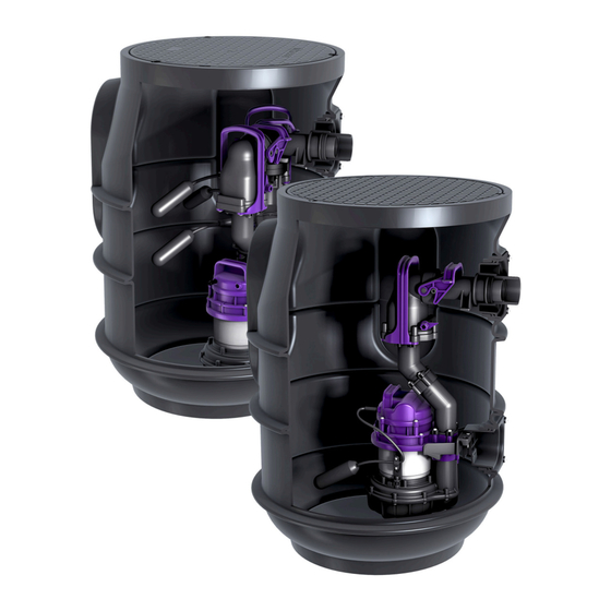
- Page 56 Product description The system is intended for underground installation, in the chamber provided, outside buildings. The system is pro- duced for equipping with one or two pumps (mono/duo). The layout of the two pumps and their piping is symmetrical. Versions: Mono (with float switch) Mono Tronic (with control unit) Duo Tronic (with control unit)
- Page 57 Mono Cover plate Drilling surfaces for inlet, conduit pipe, ventilation Tank Connecting socket for pressure pipe (DN 50) Bracket for alarm probe (optional) Backflow preventer Wastewater pump with float switch 016-102_01 DE_EN_FR Pumping station / Installation and operating manual 57 / 144...
- Page 58 Mono Tronic / Duo Tronic Cover plate Drilling surfaces for inlet, conduit pipe, ventilation Level detection with float switch Tank Control unit Connecting socket for pressure pipe (DN 50) Backflow preventer Wastewater pump Wastewater pump (Duo) 58 / 144 Pumping station / Installation and operating manual 016-102_01 DE_EN_FR...
- Page 59 How it works 016-102_01 DE_EN_FR Pumping station / Installation and operating manual 59 / 144...
- Page 60 Type plate Name of the system Article number Aqualift F Mono/Duo Connection voltage and connection fre- XXXXX quency, current consumption range U=XXXV; XX Hz; I=XXA Maximum delivery rate / pumping height Qmax=Xm³/h; Hmax=Xm Operating mode + protection rating (IP) S1; IPXX (XmWs) Ser.
- Page 61 Displays, operating keys and their functions Control unit Ready for operation LED (green) Alarm LED (red) LED system tank switch-on level reached (orange) LED wastewater pump running (orange) LED wastewater pump run- ning (orange, only Duo Tronic) Operation symbol Aqualift Basic Switch off (acknowledge) alarm button System tank symbol Wastewater pump on (manual) button...
-
Page 62: Technical Data
Technical data Technical data Performance and pumping height of the pump Pump H [ m ] Information / pump type STF 1300 Weight 10 kg Power P1 / P2 1.3 kW / 0.8 kW Speed 2650 rpm STF 1300 Operating voltage 230 V;... - Page 63 Chamber Information / chamber type Values Weight 16 kg 100 / 150 Inlet [DN] Must be drilled on-site Pressure connection [DN] 50 (d=63 mm) for PVC Conduit pipe Must be drilled on-site Aeration/ventilation Must be drilled on-site Height 830 mm Outside diameter 600 mm Cover plate / version...
-
Page 64: Installation
Installation Soil excavation and placement of the system Ensure suitability of product (variant) for environmental conditions (see "Intended use", page 53) and installation depth (see "Product description", page 56). Determine embankment gradient (ca. 60°). Excavate installation pit. In doing so, ensure that there is a footing of at least 50 cm around the base. - Page 65 Deeper installation For larger installation depths, the optional extension section Art. no. 829100 can be used. Lay seal in the chamber, correctly positioned. Insert the extension section into the chamber and level with ground. 016-102_01 DE_EN_FR Pumping station / Installation and operating manual 65 / 144...
- Page 66 Pipe connections Connect inlet/ventilation pipe Determine position for pipe connections. Select drill with appropriate hole saw (Art. no. 500101). Carry out drilling in accordance with the hole saw instruc- tions. Insert appropriate pipe seals. Grease inlet/ventilation pipe and slide through the pipe seals.
- Page 67 Establish cable pass-through Conduit pipe connection (variant A) The conduit pipe is to be installed with max. 45° bend. Select drill with appropriate hole saw (Art. no. 500101). Carry out drilling for the conduit pipe in accordance with the hole saw instructions. Insert conduit pipe seal.
- Page 68 Fit and install pump Grease seal. Mount fittings to pump and fasten in place with screws. Hang pump in place. Connect pump to pressure pipe con- nection. Lock the quick-release closure in posi- tion. Feed cable through the conduit pipe and connect electrically.
- Page 69 Fit float switch bracket (Tronic) Insert float switch. Lock float switch bracket in place with the twist lock. Carry out electrical connection at the control unit (see "Electrical connection", page 75). 016-102_01 DE_EN_FR Pumping station / Installation and operating manual 69 / 144...
- Page 70 Fit alarm probe (option, only Mono with float switch) Alarm probe (Art. no. 20222, 20223) Screw probe bracket onto pre-assembled adapter. Clip the probe to the bracket. 70 / 144 Pumping station / Installation and operating manual 016-102_01 DE_EN_FR...
- Page 71 Fit shut-off valve (option) Open quick-release closure on the pump and lift pump out by the handle. Loosen and remove screws. Remove pressure pipe and lip seal. Fit shut-off valve with new lip seal. Fasten shut-off valve with the screws. Hang pump in place and connect to pressure pipe con- nection.
- Page 72 Fitting the cover plate Grease seal and place in the chamber, correctly posi- tioned. Fasten cover plate with screws. Leak test Ensure that the system is de-energised, clean and free of building debris. Feed clear water into the system tank until it reaches the top edge of the system tank (not the extension section).
- Page 73 5.10 Backfill the excavation pit Fill the excavation pit with suitable filling material (ballast with size 0/16 grain, 50 cm all round), whilst compacting the filling material properly (e.g. with a vibrating plate) to 30 cm Dpr ≥ 95% every 30 cm. For proper fastening, surround the base section with lean concrete (see lean concrete wedge in the figure).
- Page 74 5.11 Control unit (Tronic) 5.11.1 Installing the control unit Select installation position taking the following into account: There is a safety socket in the direct vicinity of the con- trol unit. The connecting cable from the wastewater pump and float switch can be installed correctly and routed to the control unit.
- Page 75 5.11.2 Electrical connection DANGER Danger through incorrectly dimensioned connection cables. The system is intended exclusively for operation with the connection pipes provided (or equivalent). In case of doubt, contact the manufacturer/supplier. Lay the connection cable securely (e.g. conduit pipe) from the system tank to the control unit. Ensure that there is adequate cable length for the maintenance of the elec- trical components.
- Page 76 Fasten strain relief for all connection cables - tightening torque 0.5 Nm. Fit battery connector onto the battery. Route the battery cable such that the LEDs are not cov- ered or trapped. Fit the housing cover and fasten in place - screw tighten- ing torque 1.2 Nm.
- Page 77 (1) Voltage (3) Float switch (4) Alarm Brown Yellow Connection for external remote sig- nal generator / potential-free contact Blue White Connection for external remote sig- Green/yellow Pink nal generator / potential-free contact Brown (2) Wastewater pump Grey Green/yellow Green Blue Not used Brown...
- Page 78 Connect potential-free contact / remote signal generator A potential-free contact can be connected to the control unit, available as KESSEL accessory, art. no. 80074. After connecting the control unit to the mains, press the alarm button (7) and pump button (9) simultaneously for 5 seconds.
-
Page 79: Commissioning
Commissioning ✓ The initialisation starts and the 4 LEDs illuminate consec- Observe EN 12056-4 for the commissioning. utively, a signal tone sounds and the wastewater pump is Checking the system switched on for a few seconds. ✓ After successful initialisation, the control unit is ready for Check the following points before commissioning: operation and the green LED (1) illuminates. - Page 80 The functional check is successful if the following procedures are carried out as described: ✓ Level alarm is triggered, the alarm LED (2) flashes red, a signal tone is generated and the wastewater pump starts to empty the system tank. ✓...
-
Page 81: Operation
Operation Mono (variants with float switch) Switching on/off The pump is switched ON and OFF via the float switch. Mono Tronic / Duo Tronic 7.2.1 Automatic operation The system is in automatic operation, if there are no errors detected and the operating LED (1) is illuminated in green. The wastewater pump is switched on and off in accordance with the wastewater level. - Page 82 7.2.2 Alarm statuses System tank too full alarm If the level in the system tank exceeds the alarm level (float switch), the alarm is triggered, the alarm LED (2) flashes and a signal tone is generated. The wastewater pump is running. This alarm status cannot be acknowledged, it is only switched off after successful pumping off.
- Page 83 7.2.3 Overview of LED displays - Information Flashing pattern LED 1 - 4 Flashing Lights up / switched on Switched off Flashing alternately Flashing simultaneously Aqualift Basic Acoustic signal Description Measure Green Orange Orange Red (2) (interval) (4) / (5) Operating states Ready for operation System tank full, will...
- Page 84 Acoustic signal Description Measure Green Orange Orange Red (2) (interval) (4) / (5) Alarm statuses / errors Battery error Replace battery Power outage, mains voltage Reinstate mains volt- failed, system non-functional age, acknowledge alarm Level error, illogical sequence of levels detected Max run time / max run occur, wastewater pump switch Acknowledge alarm...
- Page 85 Acknowledge alarm If a condition arises that triggers an alarm, this will be indi- cated through the illumination of the alarm LED (2) and, if applicable, one of the other LEDs. After rectifying the cause of the alarm, the alarm can be acknowledged by pressing the button (7).
- Page 86 Activate manual operation Press button (9) / (10), the manual operation LED (4) / (5) flashes orange. The wastewater pump can be switched on as follows when manual operation is activated: Switching on briefly Press button (9) / (10) 1x. ✓...
- Page 87 7.2.5 Switching off the system Unplug the mains plug for the control unit, wait for a few seconds until the power outage alarm is activated (short, repetitive signal tone and the alarm LED (2) flashing) Press and hold the alarm button (7) until the alarm LED (2) no longer flashes, four short signal tones sound and the control unit is switched off If the control unit is switched off, the battery connection...
-
Page 88: Maintenance
Maintenance Observe EN 12056-4 for maintenance. Maintenance interval According to standard specifications, maintenance must be carried out at the following intervals: Quarterly for systems in commercial operations Every six months for systems in apartment buildings Annually for systems in single-family homes Visual inspection The system must be checked once every month by the operator through observation of two switching cycles for... - Page 89 Pull out the pump, complete with pressure pipe, by the handle. Check the pump parts for deformation and deposits, con- tact KESSEL service department if necessary. Ensure the moving parts can move easily. Carry out a visual check of the fitting components.
- Page 90 Cleaning/servicing the multi-vane impeller Remove the spiral housing. Check the multi-vane impeller for deformation and deposits. Remove the multi-vane impeller and clean with a water bath. Clear the ventilation pipe. Assemble the pump again in reverse order. 90 / 144 Pumping station / Installation and operating manual 016-102_01 DE_EN_FR...
- Page 91 Level measurement Open the twist lock. Pull the alarm probe (optional) and float switch out of the brackets. Immerse parts in a water bath for cleaning and wipe off with a damp cloth afterwards. Assemble the components again in reverse order. 016-102_01 DE_EN_FR Pumping station / Installation and operating manual 91 / 144...
- Page 92 Backflow preventer Loosen the screws. Remove flap housing. CAUTION Accumulated wastewater flows out! Clean flap housing and backwater flap in a water bath. Make sure that the backwater flap can move freely. Re-fit flap housing. Check tank for serious contamination, clean if necessary. Sharp devices are not suitable.
-
Page 93: Troubleshooting
Troubleshooting Error Cause Remedial measures No mains voltage available Check mains voltage Main power circuit breaker has tripped Switch circuit breaker on again Connection cable damaged Repair only by qualified electricians/service partners Pump is not running Float switch defective Contact Customer Services Overheating Submersible pump switches back on again automatically when the temperature has... - Page 94 Sommaire Chère cliente, cher client, En qualité de producteur de pointe de produits novateurs Informations spécifiques aux présentes instruc- dans le domaine de la technique d’assainissement, KESSEL tions................. propose des réponses systématiques globales et un ser- Sécurité..............vice orienté aux besoins de la clientèle. Nous misons simul- Introduction..............
-
Page 95: Informations Spécifiques Aux Présentes Instruc
Informations spécifiques aux présentes Sécurité instructions Les instructions emploient les pictogrammes suivants : Les conventions de représentation suivantes facilitent l’orien- Picto- gramme / Signification tation : label Représentation Explication voir figure 1 Activer l’appareil ! Numéro de repère 5 de la figure ci-contre Action de la figure Observer le mode d'emploi Vérifier si la com-... - Page 96 à la mise en pratique de formations se rappor- tant aux consignes de sécurité, de le protéger contre l’utilisation par des personnes non autorisées. Personne Activités autorisées sur les systèmes KESSEL Exploitant Contrôle visuel, ins- pection, remplace- ment de la batterie 96 / 144 Poste de pompage / Instructions de pose et d’utilisation...
- Page 97 Personne Activités autorisées sur les systèmes KESSEL Technicien spécialisé Vidage, nettoyage (connaît et comprend les (intérieur), contrôle instructions d’utilisation) fonctionnel, configura- tion du gestionnaire Spécialiste (ouvrier spécia- Pose, remplace- lisé, suivant les instructions de ment, maintenance pose et les normes d’exécution)
- Page 98 AVERTISSEMENT ATTENTION Pièces sous tension Surfaces chaudes ! Respecter les instructions suivantes lors de travaux Le moteur d’entraînement peut atteindre des tempé- sur des câbles et raccordements électriques : ratures élevées en cours de fonctionnement. Les directives nationales s’appliquent à tous les Porter des gants de protection travaux électriques effectués sur le système.
-
Page 99: Introduction
Équipement de protection personnel prescrit ! Introduction Le port d’un équipement de protection est toujours imposé lors de la pose, de la maintenance et de l’éva- Utilisation conforme à l'usage prévu cuation du système. Le système est uniquement destiné au pompage des eaux Vêtements de protection usées ménagères avec ou sans matières fécales et ne doit Gants de protection... - Page 100 Détail de livraison Mono Cuve avec couvercle de protection Pompe (dans le carton) Canalisation de refoulement (dans le carton) Accessoires avec instructions de pose et d'utilisation (dans un sachet) Palette 100 / 144 Poste de pompage / Instructions de pose et d’utilisation 016-102_01 DE_EN_FR...
- Page 101 Mono Tronic / Duo Tronic Cuve avec couvercle de protection Gestionnaire (dans le carton) Accessoires avec instructions de pose et d'utilisation (dans un sachet) Support pour flotteur (dans le carton) Pompe(s) (dans le carton) Canalisation(s) de refoulement (dans le carton) Palette 016-102_01 DE_EN_FR Poste de pompage / Instructions de pose et d’utilisation...
- Page 102 Description du produit Le système est prévu pour une pose à enterrer, dans le regard fourni, à l’extérieur des bâtiments. Le système pré- voit l’installation d’une ou de deux pompes (Mono / Duo). La structure des deux pompes et leur tubulure sont symé- triques.
- Page 103 Mono Couvercle de protection Surfaces de perçage pour arri- vée, conduit pour câbles, ventilation Cuve Raccord pour conduite de refoulement (DN 50) Support pour sonde d'alarme (en option) Dispositif antiretour Pompe à eaux usées avec interrupteur à flotteur 016-102_01 DE_EN_FR Poste de pompage / Instructions de pose et d’utilisation 103 / 144...
- Page 104 Mono Tronic / Duo Tronic Couvercle de protection Surfaces de perçage pour arri- vée, conduit pour câbles, ventilation Détection du niveau avec interrupteur à flotteur Cuve Gestionnaire Raccord pour conduite de refoulement (DN 50) Dispositif antiretour Pompe à eaux usées Pompe à...
- Page 105 Principe de fonctionnement 016-102_01 DE_EN_FR Poste de pompage / Instructions de pose et d’utilisation 105 / 144...
- Page 106 Plaque signalétique Désignation du poste N° de référence Aqualift F Mono/ Duo Tension et fréquence d'alimen- XXXXX tation, puissance absorbée U=XXXV ; XX Hz ; I=XXA Débit maximal / hauteur de refoulement Qmax=Xm³/h ; Hmax=Xm Mode de fonctionnement + type de protection (IP) S1 ;...
- Page 107 Affichages, touches de commande et leurs fonctions Gestionnaire Voyant d'alimentation (vert) Voyant d’alarme (rouge) Voyant de niveau haut (orange) Voyant de fonctionnement de la pompe (orange) Voyant de fonctionnement de la pompe (orange, Duo Tronic uniquement) Pictogramme En service Aqualift Basic Touche Extinction de l'alarme (acquittement) Pictogramme Cuve Bouton Fonctionnement Pompe (mode manuel)
-
Page 108: Caractéristiques Techniques
Caractéristiques techniques Caractéristiques techniques Débit et hauteur de relevage de la pompe Pompe H [ m ] Indication / type de pompe STF 1300 Poids 10 kg Puissance P1 / P2 1,3 kW / 0,8 kW Régime 2650 tr/min STF 1300 Tension de service 230 volts ;... - Page 109 Regard Indication / type de regard Valeurs Poids 16 kg 100 / 150 Arrivée [DN] doit être percé sur site Raccordement de 50 (d=63 mm) pour PVC la pression [DN] Conduit pour câbles doit être percé sur site Aération / ventilation doit être percé...
-
Page 110: Montage
Montage Réalisation de l'excavation et mise en place du système S’assurer de l’adéquation du produit (de la variante) avec les conditions environnantes (cf. "Utilisation conforme à l'usage prévu", page 99) et la profondeur de pose (cf. "Description du produit", page 102). Définir l'angle de remblai β... - Page 111 Pose plus profonde Pour des profondeurs de pose plus importantes, il est pos- sible d’utiliser en option la rallonge de rehausse réf. 829100. Insérer correctement le joint dans le regard. Mettre la rallonge de rehausse en place dans le regard et l’aligner de manière à...
- Page 112 Raccords de tuyaux Raccorder la conduite d'arrivée / de ventilation Déterminer la position des raccords de tuyaux. Choisir une perceuse équipée d’une scie cloche adé- quate (réf. 500101). Procéder au perçage dans le respect des instructions de la scie cloche. Insérer des joints d'étanchéité...
- Page 113 Procéder au passage du câble Raccord du conduit pour câbles (variante A) Le conduit pour câbles doit présenter un arc maximal de 45°. Choisir une perceuse équipée d’une scie cloche adé- quate (réf. 500101). Procéder au perçage du conduit pour câbles dans le respect des instructions de la scie cloche.
- Page 114 Monter et assembler la pompe Graisser le joint Monter la canalisation de refoulement sur la pompe et fixer avec des vis. Mettre en place la pompe. Raccorder la pompe à la sortie de refoulement. Bloquer la fermeture rapide. Guider le câble à travers le conduit pour câbles et le raccorder électrique- ment.
- Page 115 Monter le support à flotteur (Tronic) Mettre en place le support à flotteur. Bloquer le support à flotteur avec une fermeture rota- tive. Faire le raccordement électrique du gestionnaire (cf. "Raccordement électrique", page 121). 016-102_01 DE_EN_FR Poste de pompage / Instructions de pose et d’utilisation 115 / 144...
- Page 116 Monter la sonde d'alarme (en option, Mono avec interrupteur à flotteur uniquement) Sonde d’alarme (réf. 20222, 20223) Visser le porte-sonde sur l'adaptateur prémonté. Clipper la sonde sur le porte-sonde. 116 / 144 Poste de pompage / Instructions de pose et d’utilisation 016-102_01 DE_EN_FR...
- Page 117 Monter le dispositif d'arrêt (en option) Déverrouiller la fermeture rapide de la pompe et retirer la pompe en la tenant par la poignée. Desserrer et retirer les vis. Retirer la conduite de refoulement et le joint à lèvre. Monter le dispositif d'arrêt avec un nouveau joint à lèvre.
- Page 118 Montage du couvercle de protection Graisser et insérer correctement le joint dans le regard. Fixer le couvercle de protection avec des vis. En cas de fuite, en éliminer la cause. Essai d'étanchéité S'assurer de l'absence de fuite. S'assurer que la pompe est hors tension, propre et exempte de gravats.
- Page 119 5.10 Remplir l’excavation Remblayer l'excavation avec des matériaux de rem- blayage appropriés (concassé présentant des grains d'une grosseur de 0/16 sur une surface circulaire de 30 cm 50 cm), sur l'ensemble de l'excavation et par couche de 30 cm, en veillant à compacter les matériaux de rem- blayage à...
- Page 120 5.11 Gestionnaire (Tronic) 5.11.1 Montage du gestionnaire Choisir l'emplacement prévu au montage en veillant aux points suivants : Proximité directe du gestionnaire d'une prise secteur avec terre. Installation correcte du câble de raccordement de la pompe et de l'interrupteur à flotteur à amener jusqu'au gestionnaire.
- Page 121 5.11.2 Raccordement électrique DANGER Risque dû au dimensionnement erroné des conduites de raccordement. Le système est exclusivement prévu pour une utili- sation avec les conduites de raccordement fournies (ou des conduites équivalentes). Demander conseil au fabricant / fournisseur en cas de doute. Poser les câbles de raccordement correctement de la cuve jusqu'au gestionnaire (se servir p.
- Page 122 Mettre en place, sur chaque câble le réducteur de ten- sion, couple de serrage 0,5 Nm. Brancher la batterie. Poser le câble de la batterie de manière à ne pas recou- vrir ni coincer les voyants. Mettre le couvercle du boîtier en place et le fixer, couple de serrage des vis de 1,2 Nm.
- Page 123 (1) Raccordement au réseau (3) Interrupteur à flotteur (4) Alarme Brun Jaune Raccord pour le report d'alarme / contact sans potentiel externe Bleu Blanc Raccord pour le report d'alarme / Vert/jaune Rose contact sans potentiel externe Brun (2) Pompe Gris Vert/jaune Vert Bleu...
- Page 124 Raccordement du contact sans potentiel / report d'alarme Il est possible de raccorder un contact sans potentiel au gestionnaire, disponible dans les KESSEL accessoires (réf. 80074). Raccorder d'abord le gestionnaire au secteur, puis appuyer pendant 5 secondes simultanément sur la touche d'alarme (7) et la touche de la pompe (9).
-
Page 125: Mise En Service
Mise en service Mise en service du système (variantes Tronic avec La norme EN 12056-4 doit être respectée lors de la mise en service. interrupteur à flotteur) Contrôle du système Initialisation du gestionnaire Alimenter le gestionnaire en tension de réseau. Vérifiez les points suivants avant la mise en service : Pose et montage corrects de la pompe ✓... - Page 126 Aqualift Basic Le contrôle fonctionnel a réussi dès que les processus sui- vants ont été effectués comme décrit. ✓ Déclenchement du niveau d'alarme, le voyant d'alarme rouge (2) clignote, un signal acoustique retentit et la pompe commence à vider la cuve. ✓...
-
Page 127: Fonctionnement
Fonctionnement Mono (variante avec interrupteur à flotteur) Marche / arrêt La pompe est MISE EN MARCHE et ARRÊTÉE au moyen de l’interrupteur à flotteur. Mono Tronic / Duo Tronic 7.2.1 Mode automatique Le système fonctionne en mode automatique sans défauts si le voyant d'alimentation vert (1) est allumé. - Page 128 7.2.2 États d'alarme Alarme de trop-plein de la cuve Le dépassement du niveau d'alarme (interrupteur à flotteur) dans la cuve déclenche une alarme, le voyant d'alarme (2) clignote et un signal acoustique retentit. La pompe démarre. L'acquittement de cet état d'alarme est impossible et il ne disparaît qu'après un pompage réussi.
- Page 129 7.2.3 Aperçu des voyants d'affichage - informations Motif de clignotement des voyants 1 - 4 Clignotent Brillent / activées Désactivées Clignotent en alternance Clignotent simultanément Aqualift Basic Voyant Signal acoustique Description Action Rouge Orange Orange Vert (1) (intervalle) (4) / (5) États de service En ordre de marche 016-102_01 DE_EN_FR...
- Page 130 Voyant Signal acoustique Description Action Rouge Orange Orange Vert (1) (intervalle) (4) / (5) Cuve pleine, le pom- Aucune démarche n'est page démarre sous peu requise, il suffit de mettre la pompe hors service via l'actionnement de la Pompage de la cuve en cours touche (8) (cf.
- Page 131 Voyant Signal acoustique Description Action Rouge Orange Orange Vert (1) (intervalle) (4) / (5) Durée limite de marche, dépassement de la durée de fonctionnement maximale de la pompe Patienter jusqu'à ce Dépassement du que le niveau d'alarme niveau d'alarme ne soit plus dépassé Dépassement du Acquitter l'alarme et rem- nombre maximal de...
- Page 132 7.2.4 Commande manuelle Voyant - Mode manuel Voyant - Mode manuel (Duo uniquement) Bouton Pompe 1 (10) Bouton Pompe 2 (Duo uniquement) L'activation du mode manuel s'effectue via le bouton (9) / (10). La pompe n'est plus automatiquement mise en service dans ce cas.
- Page 133 7.2.5 Arrêt du système Retirer la fiche de secteur du gestionnaire et patienter quelques secondes jusqu'à ce que l'alarme de panne de secteur soit activée (bref signal acoustique périodique et clignotement du voyant d'alarme (2)) Appuyer sur le bouton d'alarme (7) sans relâcher jusqu'à ce que le voyant d'alarme (2) ne clignote plus ;...
-
Page 134: Maintenance
Maintenance La norme EN 12056-4 doit être respectée lors de la main- tenance. Intervalle de maintenance Procéder à la maintenance selon les prescriptions de la norme en respectant au moins les intervalles suivants : Maintenance trimestrielle des systèmes d'entreprises commerciales, artisanales ou industrielles Maintenance semestrielle des systèmes de maisons à... - Page 135 Vérifier si les pièces de la pompe présentent des défor- mations et des dépôts. Au besoin, contacter le service KESSEL. S’assurer que les pièces mobiles se déplacent sans entrave. Procéder à un contrôle visuel des composants de la canalisation de refoulement.
- Page 136 Nettoyage / maintenance de la roue vortex Démonter la volute de pompe. Vérifier l’absence de déformations et la souplesse de fonctionnement de la roue vortex. Démonter la roue vortex et la nettoyer à l'eau. Nettoyer les orifices de ventilation. Remonter la pompe dans le sens inverse du démontage. 136 / 144 Poste de pompage / Instructions de pose et d’utilisation 016-102_01 DE_EN_FR...
- Page 137 Détection du niveau Ouvrir la fermeture rotative. Retirer la sonde d'alarme (en option) et le support pour flotteur des supports. Nettoyer l'ensemble des pièces à l'eau, puis les essuyer. Remonter les composants dans le sens inverse du démontage. 016-102_01 DE_EN_FR Poste de pompage / Instructions de pose et d’utilisation 137 / 144...
- Page 138 Dispositif antiretour Desserrer les vis. Démonter le corps de clapet. ATTENTION Les eaux usées accumulées s’échappent ! Nettoyer le corps de clapet et le clapet antiretour à l'eau claire. S'assurer de la mobilité du clapet antiretour. Remonter le corps de clapet. S'assurer que la cuve est exempte de salissures impor- tantes, nettoyer au besoin.
-
Page 139: Aide En Cas De Panne
Déclenchement du fusible principal Réactiver le fusible Cordon d'alimentation défectueux Réparation par un électricien qualifié / un parte- Pompe ne fonc- naire de SAV de KESSEL tionne pas Flotteur défectueux Informer le service après-vente si nécessaire Surchauffe La pompe submersible se remet automatique- ment en marche après la chute de la tempéra-... -
Page 140: Leistungserklärung / Declaration Of Performance
Leistungserklärung / Declaration of Performance 140 / 144 Pumpstation / Einbau- und Bedienungsanleitung 016-102_03 DE_EN_FR... - Page 144 Registrieren Sie Ihr Produkt online, um von einer schnelleren Hilfe zu profitieren! http://www.kessel.de/service/produktregistrierung.html KESSEL AG, Bahnhofstr. 31, 85101 Lenting, Deutschland...
Need help?
Do you have a question about the Aqualift F Basic and is the answer not in the manual?
Questions and answers