
Related Manuals for LevelOne WGR-2301


Summary of Contents for LevelOne WGR-2301
-
Page 1: User Manual
Introduction WGR-2301 AC750 Dualb Bandb Wireless Gigabit, Dual WAN, VPN User Manual V1.0 Digital Data Communications Asia Co., Ltd. http://www.level1.com http://www.level1.com Page 1... -
Page 2: Table Of Contents
Introduction Table of Contents Table of Contents ........................2 Factory settings ......................6 Contact Us........................6 Chapter 1. Product Overview ..................... 7 Key characteristics ..................... 7 Specifications ......................8 Chapter 2. Hardware Installation ..................9 Panel description ......................9 Precaution for installation ..................10 Preparing for installation .................... - Page 3 Introduction 6.4.3 DHCP auto binding ................... 39 6.4.4 DHCP client list ....................39 6.4.5 Case of DHCP configuration ................40 DDNS configuration ....................42 6.5.1 DDNS authentication ..................43 UPnP ........................43 Chapter 7. Wireless configuration ................... 45 Basic settings ......................45 7.1.1 AP Mode ......................
- Page 4 Introduction Figure 9_3 IP/MAC binding global configuration ..............84 9.2.2 IP/MAC binding configuration ................85 9.2.3 IP/MAC binding instances ................... 86 PPPoE Server ......................89 9.3.1 PPPoE introduction ..................... 89 9.3.2 PPPoE global Settings..................90 9.3.3 PPPoE account configuration ................92 9.3.4 PPPoE user status ....................
- Page 5 Introduction 12.3.2 Domain Block Notification ................139 MAC Address Filtering....................141 12.4 12.4.1 MAC Address Filtering ..................142 12.4.2 MAC Address Filtering Settings ................. 143 Chapter 13. For the invalid entries, the system will skip the invalid configuration entries in binding VPN ......................145 PPTP ........................
-
Page 6: Factory Settings
The factory user name of the system administrator is admin, and the factory password is admin (case-sensitive). Contact Us If you have any questions during installation or use, please contact us in the following manners. Customer service: 0800-011-110 LEVELONE discussions: http://www.level1.com E-mail support: support@level1.com http://www.level1.com Page 6... -
Page 7: Chapter 1. Product Overview
Chapter 1 Product Overview Chapter 1. Product Overview Key characteristics Supports fixed IP, dynamic IP, PPPoE, AP Client, 3G client access Supports traffic load balancing and line backup Supports policy routing Supports the Internet behavior management function ... -
Page 8: Specifications
Chapter 1 Product Overview Supports VPN function Supports UPnP Supports dynamic domain names Supports HTTP remote management Supports the WEB upgrading mode Supports backup and import of WEB configuration files The machine meets the 6KV lightning-proof feature Specifications ... -
Page 9: Chapter 2. Hardware Installation
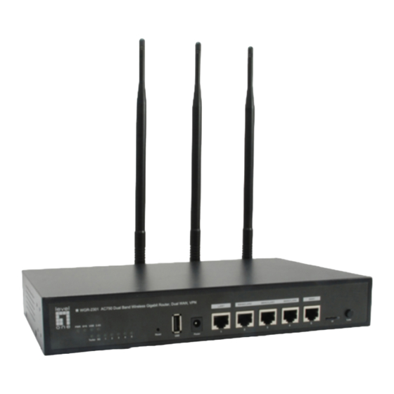
This section introduces the appearance of Progressive ™ 510W, and its front panel, back panel is shown in Figure 2-1, Figure 2-2. Figure 2-1 Diagram of front panel - Progressive WGR-2301 Figure 2-2 Diagram of rear panel - Progressive WGR-2301... -
Page 10: Precaution For Installation
Chapter 2 Hardware Installation LED that corresponds to the port stays lit, and it will flash if there is flow. The WPS feature is temporarily not supported by this software version, so the Note corresponding status LED is not used. Table 2-1 LED description Description of interfaces Interface... -
Page 11: Preparing For Installation
Chapter 2 Hardware Installation Please use the original power cord. Preparing for installation We have applied to local operators (ISP, such as China Telecom, China Unicom, etc.) for broadband services. Preparation of related devices: Modem (This item is not required when connected directly to Ethernet). Hub or switch or wireless devices. -
Page 12: Hardware Connection
Chapter 2 Hardware Installation Hardware connection 1. Establish a LAN connection Connect the LAN port of the router and a PC or a hub or a switch in LAN with a network cable. Or after the device's wireless feature is enabled, connect wireless clients or other wireless devices to the router over a wireless connection. -
Page 13: Chapter 3. Logging To The Device
Chapter 3 Logging Device Chapter 3. Logging to the device This chapter describes how to configure the correct network settings for the network computers, how to log on to the appliances and how to use shortcut icons to quickly link to the HiPER website for product information and services. -
Page 14: Logging To The Device
Chapter 3 Logging Device Pinging 192.168.1.1 with 32 bytes of data: Reply from 192.168.1.1: bytes=32 time<1ms TTL=255 Reply from 192.168.1.1: bytes=32 time<1ms TTL=255 Reply from 192.168.1.1: bytes=32 time<1ms TTL=255 Reply from 192.168.1.1: bytes=32 time<1ms TTL=255 Ping statistics for 192.168.1.1: Packets: Sent = 4, Received = 4, Lost = 0 (0% loss), Approximate round trip times in milli-seconds: Minimum = 0ms, Maximum = 0ms, Average = 0ms If the screen is shown as follows, it indicates that the connection between the computer... - Page 15 Chapter 3 Logging Device such as http://192.168.1.1. After the connection is established, you will see a login interface as shown in Figure 3-1. In the first use, you should log in as a system administrator, that is, enter your administrator username and password (the factory defaults of username, password are admin and admin respectively, which are case sensitive) on the login interface, and then click <OK>.
- Page 16 Chapter 3 Logging Device Homepage description: The top-right corner of the page displays device model, hardware version, software version and three fast link icons. These 3 shortcut icons have the following functions: Product Discussion– Link to the discussion forums of the HiPER official website to participate in discussions about the product.
-
Page 17: Chapter 4. Configuration Wizard
Chapter 4 Configuration Wizard Chapter 4. Configuration Wizard By reading this chapter, you can understand the basic network parameters required for the device to access to the Internet, and these parameters are configured to connect the device to the Internet. Before configuring "Internet Line" in the Configuration Wizard, you should properly configure the network settings of the network computer. -
Page 18: Dynamic Ip Access
Chapter 4 Configuration Wizard 4.1.1 Dynamic IP access The default WAN1 access is dynamic IP access, as shown in Figure 4-3. If your Internet access mode is dynamic IP access, please click <Next>, to complete the configuration of the WAN1 port. Figure 4-2 Configuration Wizard - Dynamic IP access 4.1.2 Static IP access If your Internet access mode is Static IP access, please select "Fixed IP access"... -
Page 19: Pppoe Access
Chapter 4 Configuration Wizard 4.1.3 PPPoE access If your Internet access mode is PPPoE access, please select "PPPoE access" in the drop-down list box of Figure 4-5 , and fill in the corresponding user name and password, and then click <Next> to enter into the next page to complete the configuration of WAN1. Figure 4-4 Configuration wizard - PPPoE access User name, password: Type in the user name, password provided by the ISP. -
Page 20: Chapter 5. Start Menu
Chapter 5 Start Menu Chapter 5. Start menu Start menu is located on the top of the Level 1 menu bar of the WEB interface, providing the interface for 4 common pages, including: configuration wizard, running status, port flow, device reboot. In the Start menu, you can quickly configure the basic parameters required by the device in working properly, view the information about the interfaces, and view the statistics data of the devices' real-time traffics. -
Page 21: Interface Traffic
Chapter 5 Start Menu Interface Traffic This section describes the Start-> Interface Traffic page, as shown in Figure 5-2. You can view the average, maximum, sum and the current real-time rate for the relevant ports to receive and send data, and provide different units (Kbit/s and KB/s) for them. Tip: If this page fails to display properly, please click the hyperlink "If it cannot display properly, please install a svgviewer"... -
Page 22: Restart Device
Chapter 5 Start Menu Display: Provides two display effect options, solid effect and hollow effect. Color: It can be selected for display according to needs and preferences, such as red, blue, orange, etc. Flip: Click the Flip button, and the colors can swap to receive and send data. Restart device If you need to restart the device, just enter into the Start->... -
Page 23: Chapter 6. Network Parameters
Chapter 6 Network parameters Chapter 6. Network parameters In the network parameter menu, you can configure the basic network parameters for the device, including WAN/LAN configuration, line combination, DHCP server, DDNS configuration and UPnP. Configuration of WAN port This section describes the Network parameters ->WAN configuration page. In this page, you can configure not only the line information, modify or delete the configured lines according to the actual needs, but also view the connection status of lines. -
Page 24: Wan1 Access
Chapter 6 Network parameters 6.1.1 WAN1 access Dynamic IP access Figure 6-2 Dynamic IP access Access mode: Selects the corresponding access mode, and "Dynamic IP access" is selected here. Operator policy: Selects the operator of the interface, with the options as follows: Operator policy, China Telecom, China Unicom and China Mobile respectively. - Page 25 Chapter 6 Network parameters Telecom routes while Unicom traffic flows on the Unicom routes. Generally, it is not recommended to modify the MAC address of interfaces. However, in some cases, the operator binds the MAC of the device, which results in the failure of the new network device to dial up successfully, and at this time, the MAC address of the device needs to be modified as that of the original network device.
-
Page 26: List Of Line Connection Information
Chapter 6 Network parameters Idle time: The time length after there is no Internet traffic of access and before automatic disconnection. 0 means no automatic disconnection. MTU: Maximum transmission unit, 1480 bytes by default. The device will automatically negotiate with the peer device in PPPoE dialup. Do not modify it unless in special applications. - Page 27 Chapter 6 Network parameters Dynamic IP access Figure 6-5 List of line connection information - Dynamic IP access As shown in the above figure, APClient port is a dynamic IP access. Connection type: In the case of "Connected", it shows the time length of the connection.
-
Page 28: Line Combination
Chapter 6 Network parameters PPPoE access Figure 6-7 List of line connection information - PPPoE access If a line is a PPPoE dialup one, then click on the interface, the "Dial-up" and "Hang-up" will appear below the "Line connection information list", as shown in the figure above, the WAN1 port is PPPoE access, click on "WAN1", and four buttons are displayed on the lower right part of the line connection information list. -
Page 29: Description Of Line Combination Function
Chapter 6 Network parameters 6.2.1 Description of line combination function Line detection mechanism Regardless of line combination modes, make sure that the network is not interrupted when the line fails, which require that the device must be able to monitor line status in real time. -
Page 30: Global Configuration Of Line Combination
Chapter 6 Network parameters Line combination mode The device provides 2 line groups: "Main line" group and "Backup line" group. For convenience's sake, the lines in the "main line" group are collectively known as main line, and the lines in the "backup line" group are collectively known as backup line. All lines are main lines by default. - Page 31 Chapter 6 Network parameters Figure 6-8 Full Load Balancing Line load balancing mode: "All line load balancing" is selected here. Save: The line combination configuration parameters take effect. Refill: Restores to the configuration parameters before modification. Tip: Line combination mode is "All line load balancing" by default. Partial Load Balancing Figure 6-9 Partial Load Balancing Line combination mode: "Partial line load balancing while the others backed up"...
-
Page 32: Load Balancing List
Chapter 6 Network parameters "Main line" list box. Save: The line combination configuration parameters take effect. Refill: Restores to the configuration parameters before modification. 6.2.3 Load Balancing List In the Network parameter -> Line combination -> Line combination status information page, you can view, configure the information of configuration line. Figure 6-10 Load Balancing List Edit the line combination status information: Click on the interface of the line or the "Edit"... -
Page 33: Identity Binding
Chapter 6 Network parameters Figure 6-11 Line combination configuration Interface: Selects access modes (WLAN, 3G, APClient) WAN1 configuration: Configure WAN1 to provide access to intranet users. 3G client configuration: The device provides access to intranet users as a 3G client. -
Page 34: Configuration Of Lan Port
Chapter 6 Network parameters configuration -> Identity binding page to enable the identity binding function. In the case of multi-line session load balancing, NAT sessions in the same application may be distributed in different lines, which will cause such applications as online bank, QQ, etc. -
Page 35: Dhcp Server
Chapter 6 Network parameters Figure 6-13 Configuration of LAN port IP address: Sets the LAN IP addresses, and the first IP address is 192.168.1.1 by default, while the other three IP addresses are 0.0.0.0 by default. Subnet mask: Sets the subnet mask of the corresponding IP address, which is 255.255.255.0 by default. -
Page 36: Dhcp Server Configuration
Chapter 6 Network parameters DHCP server settings, static DHCP and DHCP automatic binding and DHCP client list. 6.4.1 DHCP server configuration Figure 6-14 Configuring the DHCP service Enable DHCP server: Used to disable or enable the device's DHCP server function. Selecting it means allow. -
Page 37: Static Dhcp
Chapter 6 Network parameters Primary DNS server: The IP address of the primary DNS server automatically assigned by the DHCP server to the network computers. Secondary DNS server: The IP address of the secondary DNS server assigned by the DHCP server to the network computers automatically. Enable DNS proxy: Selecting it means enabled. - Page 38 Chapter 6 Network parameters Figure 6-15 Static DHCP list Static DHCP configuration Click <Add new entry> in the page as shown in Figure 6-15, to enter into the Static DHCP configuration page as shown in the figure below. Below is a description of the meaning of the parameters for configuring static DHCP.
-
Page 39: Dhcp Auto Binding
Chapter 6 Network parameters Tip: After the setting is successful, the device will assign the preset IP address for the specified computer in a fixed way. The assigned IP addresses must be within the range provided by the DHCP server. 6.4.3 DHCP auto binding Below is the description of DHCP automatic binding function. -
Page 40: Case Of Dhcp Configuration
Chapter 6 Network parameters Figure 6-18 DHCP client list 6.4.5 Case of DHCP configuration Application requirements In this example, the device must have the DHCP function enabled, and the starting address is 192.168.1.10, with a total number of 100 allocable addresses. The host with the MAC address of 00:21:85:9B:45:46 assigns the fixed IP address of 192.168.1.15, while the host with the MAC address of 00:1f:3c:0f:07:f4 assigns the fixed IP address of 192.168.1.10. - Page 41 Chapter 6 Network parameters Figure 6-19 DHCP service settings - Instance The third step is to enter the Network parameters -> DHCP server-> Static DHCP page, and click <Add new entry>, to configure the two static DHCP instances in the request (such as Figure 6-21, Figure 6-22).
-
Page 42: Ddns Configuration
Chapter 6 Network parameters Figure 6-21 Static DHCP configuration - Instance B At this point, the configuration is complete, and you can view the information about 2 static DHCP entries in the "Static DHCP information list", as shown in Figure 6-23. If configuration errors are found, you can click the corresponding item's icon directly and enter into the Static DHCP configuration page for modification and saving. -
Page 43: Ddns Authentication
Chapter 6 Network parameters Dynamic DNS (DDNS) is a service to resolve a fixed domain name to a dynamic IP address (such as ADSL dial-up Internet access) services. You need to apply to the DDNS service provider for this service, and various service providers provide the specific service of DDNS according to the actual situation. - Page 44 Chapter 6 Network parameters used for PCs and intelligent devices (or instruments). Using UPnP means simpler, more choices and more innovative experiences. The network products supporting Universal Plug and Play need only be physically connected to the network to begin to work. This section describes the Network parameters ->UPnP page and configuration.
-
Page 45: Chapter 7. Wireless Configuration
Chapter 7 Wireless configuration Chapter 7. Wireless configuration In the wireless configuration, the relevant wireless functions and parameters are mainly set in the device, including: basic settings, wireless security settings, wireless MAC address filtering, and wireless advanced configuration. In addition, you can also view the status information about the wireless host. -
Page 46: Ap Mode
Chapter 7 Wireless configuration 7.1.1 AP Mode Figure 7-1 AP Mode Enable wireless function: Only after the wireless function is enabled can the wireless clients be connected to the device, to have wireless communications through the device, connect and access the cable network to which the device is connected. AP working mode: The AP Mode is selected here, namely the pure AP mode, in which the peer device can be an AP Client mode and single client. -
Page 47: Repeater Mode
Chapter 7 Wireless configuration Channel: This parameter is used to select the frequency bands in which the wireless network works, with the available range from 1 to 11, and it provides automatic options, which means that the device can automatically select the optimal frequency band. - Page 48 Chapter 7 Wireless configuration Figure 7-2 Repeater Mode For the meaning of enabling wireless function, AP working mode, SSID, wireless mode, channel, channel bandwidth, enabling SSID broadcast, see Section 7.1.1 AP Mode for relevant explanations, and these terms will no longer be detailed if any in the subsequent configuration.
-
Page 49: Bridge Mode
Chapter 7 Wireless configuration TKIP: It means that the TKIP encryption algorithm is used to protect communication data during the data exchange process. For details, please refer to the section 7.2.4 WPA-PSK/WPA2-PSK. AES: It means that the AES encryption algorithm is used to protect communication data during the data exchange process. -
Page 50: Lazy Mode
Chapter 7 Wireless configuration 7.1.4 Lazy Mode The device can exchange data with network devices and single clients in the Repeater Mode, Bridge Mode when its work mode is Lazy Mode, to realize network connectivity. Figure 7-4 Lazy Mode The meaning of related configuration parameters is the same as AP Mode and Repeater Mode. - Page 51 Chapter 7 Wireless configuration Figure 7-5 AP Mode networking environment 1. Requirements: Some home users want to put desktop computer, laptop, Tablet PC, smart phones on the Internet via wireless devices, and prevent users other than their home from accessing to wireless devices. 2.
- Page 52 Chapter 7 Wireless configuration Figure 7-6 AP Mode configuration Enter into the Wireless configuration -> Wireless security settings page, to configure the authentication modes and key for wireless communication. Through the above configuration, wireless users can connect to the wireless devices so long as they pass the authentication, and access to the Internet through it.
- Page 53 Chapter 7 Wireless configuration Device A, and access to the Internet through Device A. 2. Analysis: Achieved by the following solutions Solution I: Devices A and B are set to Repeater Mode. Solution II: Devices A and B are set to Bridge Mode. Solution III: Devices A and B are set to Repeater Mode, Bridge Mode respectively.
-
Page 54: Wireless Security Settings
Chapter 7 Wireless configuration Figure 7-8 Repeater Mode instance Configure the AP mode of Device B as Repeater Mode, and the SSID, wireless mode, channel, channel bandwidth, security mode, pre-shared key are configured in the same way as Device A, and the AP MAC address is: 0022AABB5428 (the MAC address of Device A). -
Page 55: No Security Mechanism
Chapter 7 Wireless configuration 7.2.1 No security mechanism Figure 7-9 None Security mechanism: "No security mechanism" is selected here, which means that this device does not allow any security mechanism to authenticate the other wireless devices or wireless clients of the access device. 7.2.2 WEP Figure 7-10 WEP Security mechanism: Selecting "WEP"... -
Page 56: Wpa/Wpa2
Chapter 7 Wireless configuration authentication key. To perform data transmission, you must provide the correct key. Shared key: Here, the wireless client host must provide a correct key to pass the authentication; otherwise, it cannot be associated with the wireless devices, and cannot perform data transmission. -
Page 57: Wpa-Psk/Wpa2-Psk
Chapter 7 Wireless configuration use the Radius server for authentication and obtaining the key. WPA version: Sets the security mode this device will use: Auto: Means that the device can automatically choose WPA or WPA2 safe mode according to the requests of wireless client. ... -
Page 58: Wireless Mac Address Filtering
Chapter 7 Wireless configuration security mechanism, this device will use the WPA mode based on the Pre-Shared key. WPA version: Sets the security mode this device will use: Auto: Means that the device can automatically choose WPA-PSK or WPA2-PSK safe mode according to the requests of wireless clients. - Page 59 Chapter 7 Wireless configuration Figure 7-13 Wireless MAC Address Filtering Enable MAC address filtering: Enable or disable the MAC address filtering function, checking it means to enable it. Filtering rules: Sets the rules for MAC address filtering. Permission: Only allows the MAC addresses in the list to access the wireless network: It indicates that only the wireless clients that correspond to the MAC addresses in the MAC address filtering information list are allowed to access to the device but disallow the wireless clients out of the filtering table to access.
-
Page 60: Wireless Advanced Configuration
Chapter 7 Wireless configuration Wireless Advanced Configuration This section describes the meaning of the wireless advanced parameters in the Wireless Configuration-> Advanced. In this page, you can set wireless advanced parameters, and under normal circumstances, keep the default values of these parameters. If you have special needs, you can configure in this page. -
Page 61: Client List
Chapter 7 Wireless configuration 256-2346 bytes, and the default is 2346 bytes. The transmission efficiency for large segments is high, but if there is a clear conflict in the wireless network, or if the network is used at a high frequency, the reduction of segments can improve the reliability of data transfer. - Page 62 Chapter 7 Wireless configuration Figure 7-16 Client List ID: Serial number. MAC address: The MAC address of the wireless host. Filter: Selecting it to indicate that the current MAC address has been added into the "List of MAC address filter information" (which can be viewed in the Wireless configuration -->...
-
Page 63: Chapter 8. Advanced Configuration
Internet, it is reflected as limited range of public network IP addresses. Since the internal network can be effectively isolated from the outside world, so NAT can also provide some assurance for network security. LEVELONE routing products provide flexible NAT function. The following will detail its characteristics. NAT address space... -
Page 64: Port Forwarding
Chapter 8 Wireless configuration to the Intranet server through the device, at this point, the static NAT mapping or virtual server (DMZ host) needs to be set up on the device in order to achieve this objective. With the static NAT mapping function, a one-to-one mapping relationship can be established between<External IP address + External port>and<Internal IP address + Internal port>, so that all the service requests for a specified port of the device will be forwarded to the matching intranet server, and the computer in the external network can access to the services provided by this server. - Page 65 Chapter 8 Wireless configuration the meaning of the parameters for the static NAT mapping list and the static NAT mapping configuration. Port Forwarding list Figure 8_1 Port Forwarding list Tip: After enabling certain functions of the system, the list displays some NAT static mapping entries (A static mapping entry named as "admin"...
- Page 66 Chapter 8 Wireless configuration Figure 8_2 Port Forwarding Settings Static mapping name: The name of static NAT mapping, which is custom and cannot be repeated. Enable this configuration: Selecting it indicates that the static NAT mapping takes effect, and not selecting it means that the static NAT mapping does not take effect, but retains its configuration.
-
Page 67: Nat Rules
Chapter 8 Wireless configuration 8.1.3 NAT rules The NAT rules features of the device are described below, including: NAT rule info lists, meaning of Easy IP NAT rules configuration parameters, meaning of One2One NAT rules configuration parameters. List of NAT rules information In NAT rules information list, you can see the configured NAT rules. - Page 68 Chapter 8 Wireless configuration Figure 8_4 Easy IP Rule name: Customizes the name of the NAT rule. NAT type: Selects EasyIP here, which means the internal IP address are mapped to the same external IP address. External IP address: In the NAT rule, the external IP address mapped to the internal IP address.
-
Page 69: Dmz
Chapter 8 Wireless configuration subject to one-to-one mapping. External starting IP address: In the NAT rule, the external starting IP address mapped to the internal starting IP address. Tip: Each One2One rule can only bind 20 external addresses at maximum. "External starting IP address"... -
Page 70: Nat And Dmz Configuration Instances
Chapter 8 Wireless configuration 8.1.5 NAT and DMZ configuration instances This section describes the specific instances of NAT and DMZ configuration. Includes: Static NAT mapping instances, instances with the type of NAT rules as EasyIP, One2One. 一、 Instances of Static NAT mapping configuration Intranet computer 192.168.1.99 starts the TCP80 port services, and wants to access this service through WAN1 port 80. - Page 71 Chapter 8 Wireless configuration "Rule name". The third step is to select "NAT type" as "EasyIP". The fourth step is to fill in 218.1.21.3 in the "External IP address". Fill in 192.168.1.10 and 192.168.1.100 in "Internal starting IP address" and "Internal ending IP address" respectively. The fifth step is to select the rule-bound interface as WAN1 port.
-
Page 72: Static Route Settings
Chapter 8 Wireless configuration the fixed IP access to the default Internet line in Network parameters —> WAN port configuration page, or directly enter the Start--> Configuration wizard > Network parameter spage to configure the line. After the default Internet access line is configured correctly, the system-reserved NAT rules corresponding to the default line will be automatically generated, and the NAT function is automatically enabled. - Page 73 Chapter 8 Wireless configuration Static route is manually configured by a network administrator, making the transmission of packets to the specified destination network be realized according to the predetermined path. Static routing does not change with changes in the structure of the network, therefore, when network structure changes or there is a network failure, you need to manually modify the static routing information in the routing table.
-
Page 74: Policy Routing
Chapter 8 Wireless configuration Routing name: The name of static routes (custom, no repetition). Enable this configuration: Enables this static route. Selecting it means enabled, while deselecting it means the route is disabled. Destination network: The destination network number for this static route. Subnet mask: The mask of the destination network for this static route. -
Page 75: Enable Policy Routing
Chapter 8 Wireless configuration 8.3.1 Enable policy routing Figure 8_12 Policy routing list Enable policy routing: This is a global switch of policy routing. Only after it is enabled can the configured policy routing can take effect. Move to: Users can appropriately sort the policies using this bLeveloneon. 8.3.2 Policy routing configuration Click <Add new entry>... - Page 76 Chapter 8 Wireless configuration Figure 8_13 Policy routing configuration Interface: Sets the physical interface bound by the policy routing, and the packets that meet the conditions of policy routing will be forwarded from the bound interface. Policy route name: Customizes the name of the policy. Source address: The source IP address of the packets following this policy route, which can be configured in two ways.
-
Page 77: Anti-Netsniper
Chapter 8 Wireless configuration protocol is ICMP, the port range needs not be configured. Effective time setting: Selects the time period for the policy routing takes effect, and the default date is "Every day". The time is "All day". You can go to Advanced settings —> Configure policy route page to edit the time for the policy route to take effect. -
Page 78: Port Vlan
Chapter 8 Wireless configuration configuration interface is shown in the figure below. Figure 8_15 Port mirroring Enable mirroring: Checking it to enable this feature. When the HiPER 840G device supports two or more LAN ports, the port mirroring function can work. - Page 79 Chapter 8 Wireless configuration Figure 8_16 Port VLAN list VLAN group number: Displays the VLAN group number of the VLAN. VLAN group name: Displays the VLAN group name of the VLAN. VLAN members: Displays the members to the VLAN. 4. Port VLAN Figure 8_17 Port VLAN settings VLAN group number: Sets the VLAN group number.
-
Page 80: Syslog Configuration
Chapter 8 Wireless configuration A VLAN can contain more than one port, and one port can belong to more than one VLAN. 5. Instances of Port VLAN Requirements: The host under the LAN1 port can communicate with the hosts under the LAN2, LAN3 ports, but those under the LAN2 and LAN3 ports cannot access to each other. -
Page 81: Chapter 9. User Management
Chapter 9 Wireless configuration Chapter 9. User management This chapter describes the secondary menu under the primary menu of user management, including: User state, IP/MAC binding, PPPoE server, WEB authentication, user group configuration. User status This section describes the User management-> User status page. Administrators can understand all intranet users' net behaviors, the traffic occupied by the net behaviors and the status of each user, and so on by viewing, analyzing the pie charts and lists in this page. -
Page 82: Figure 9_2 User Status Information List
Chapter 9 Wireless configuration The following describes the list of user status information, through checking of which, administrators can learn about each online user's online time, real-time upload/download rate, total uplink/downlink traffic, net behaviors, etc. Figure 9_2 User status information list The first column of user status information displays if each user's net behaviors are affecting work, whose status includes: Severe (red), minor (yellow), normal (green). -
Page 83: Ip/Mac Binding
Chapter 9 Wireless configuration Group: Displays the group to which the user belongs. Net behavior: Displays the user's net behaviors. Settings: Click the icon. If you want to clear the user's net behavior statistics, please click "Clear data". Note: Click on the icon to modify the description information of PPPoE dial-up user, WEB authenticated user. -
Page 84: Ip/Mac Binding List
Chapter 9 Wireless configuration 9.2.1 IP/MAC binding list Figure 9_3 IP/MAC binding global configuration Allow non-IP/MAC bound user to connect to the device: Allows or disallows the non-IP/MAC bound users to connect to the device, and access to other networks through the device. -
Page 85: Ip/Mac Binding Configuration
Chapter 9 Wireless configuration Tip: Before deciding to cancel the "Allow non-IP/MAC bound user to connect to the device" function, you must make sure that the management computer has been added to the "IP/MAC binding information list", otherwise it will cause the management computer to be unable to connect to the device. -
Page 86: Ip/Mac Binding Instances
Chapter 9 Wireless configuration Binding: Binds all the IP/MAC entries in the text box. Tip: In the above input format, there may be one or more spaces between the IP and MAC, MAC and username. For the invalid entries, the system will skip the invalid configuration entries in binding. 9.2.3 IP/MAC binding instances Flexibly using the IP/MAC binding feature can configure "white list"... - Page 87 Chapter 9 Wireless configuration Figure 9_6 IP/MAC binding information list – Instance I Configure "Black list" of Internet access for intranet users, following these steps: First, specify the illegal user by configuring the IP/MAC binding entries, and there are two methods: Use the IP address of the host that is prohibited from Internet access and the MAC address of any of the non-intranet adapter as the IP/MAC address binding pair, and add it into the...
- Page 88 Chapter 9 Wireless configuration Figure 9_7 IP/MAC binding information list – Instance II For example, if you want to prohibit a host with the IP address of 192.168.1.30 and the MAC address of 0021859b2564 from connecting and passing the device, you can add an IP/MAC address binding pair, enter the host's IP address and MAC address, and deselect "Allow"...
-
Page 89: Pppoe Server
Chapter 9 Wireless configuration PPPoE Server This section describes the device's PPPoE function, including: PPPoE introduction, PPPoE global configuration of device, configuration of PPPoE accounts and viewing of PPPoE connection status. 9.3.1 PPPoE introduction PPPoE (Point-to-Point Protocol over Ethernet). It allows a host on the Ethernet to connect to the Internet through a simple access device. -
Page 90: Pppoe Global Settings
Chapter 9 Wireless configuration same as that in the PADI packet. If the PPPoE server cannot provide services to PADI, it is not allowed to use the PADO packet to respond. PADR: Since PADI is sent as a broadcast, the PPPoE client may receive more than one PADO packet, and it will review all the PADO packets received and choose a PPPoE server based on the server name in it or the services provided, and then send a PADR (PPPoE Active Discovery Request) packet to the selected server. - Page 91 Chapter 9 Wireless configuration Figure 9_10 PPPoE Global Settings Enable PPPoE server: Enables/disables the PPPoE server function of the device. Select it to enable. Forcing PPPoE authentication: Enabling it means to only allow the users who pass the intranet PPPoE authentication to access the Internet. Exception address group: After the device enables the forcing PPPoE authentication, the users of the address group can communicate with external network without dial-up authentication, and the address group needs to be configured in the User management ->...
-
Page 92: Pppoe Account Configuration
Chapter 9 Wireless configuration system to be established. Tip: The steps that PPPoE users change the dial-up password: 1) Users open the dial-up client, and dial up using the user name, password. 2) After a successful dial-up, log into the self-service page, whose address is: http://192.168.1.1/poeUsers.asp (the address is the LAN IP address for the device). - Page 93 Chapter 9 Wireless configuration User name: The user name of PPPoE dial-up users. Enable: If the user is allowed to access the Internet. Checking it means allow. Fixed IP address: Displays the IP address bound to that user name. Charging mode: When the charging feature is enabled, the "by date" will be displayed (which currently supports charged by date).
-
Page 94: Pppoe User Status
Chapter 9 Wireless configuration User name: The account (custom, not repeatable) used by users in initiating PPPoE connections for the PPPoE server to authenticate, the value range is: 1-31 characters. Password: The password used by users in initiating PPPoE connections for the PPPoE server to authenticate. -
Page 95: Export Pppoe Accounts
Chapter 9 Wireless configuration you can view the account information used; if users use the configured user name to connect to the PPPoE server, we can see such information of the IP addresses, the user's MAC address, online time of PPPoE connections, upload/download rates, etc. the PPPoE server assigns to the user in the list. -
Page 96: Import Pppoe Accounts
Chapter 9 Wireless configuration Figure 9_14 Export PPPoE Accounts Export account: Click this bLeveloneon to export all PPPoE accounts in the list, including the user name, password for the account, in the. txt format. 9.3.6 Import PPPOE Accounts Figure 9_15 Import PPPOE Accounts Tip: When configuring PPPOE accounts to be imported and bound in batch, its input format is "Account + password", for example, test 123456, each row can have only one configuration... -
Page 97: Instance Of Pppoe Server Configuration
Chapter 9 Wireless configuration 9.3.7 Instance of PPPoE server configuration Demand: Only the users authenticated by the Intranet can access the Internet. Now, 3 accounts are configured for intranet users, and their user names are test1, test2, and test3 respectively. Initial passwords are: password1, password2, password3, in which test1, test2 are separately bound with 10.0.0.1, 10.0.0.2 and the charging feature is enabled (the using period of the account is from October 1, 2012 to December 31, 2013) and a notification is issued 15 days prior to account expiration;... - Page 98 Chapter 9 Wireless configuration Figure 9_17 PPPoE account Settings Repeat Step 2, and configure the account with the PPPoE user name as test2. Bind it with 10.0.0.2. Configure the account of test3, and set the maximum number of sessions for its account to 5.
-
Page 99: Web Authentication
Chapter 9 Wireless configuration WEB authentication 9.4.1 WebAuth Global Settings Enter the User management->WEB certification page to configure the WEB authentication feature of the device. WEB Authentication is used to authenticate Intranet users as to having permission to access the Internet, that is, after enabling this feature, the intranet users cannot access to the Internet unless passing the WEB authentication. -
Page 100: Web Authentication Account List
Chapter 9 Wireless configuration Window title: The title of the custom WEB authentication pop-up window. Window tip text: Tip texts for custom WEB authentication pop-up window. Network image link: Enters the network link to the picture, to make this picture as the background of the WEB authentication pop-up window. - Page 101 Chapter 9 Wireless configuration User name: Displays/configures the user name of the WEB authentication user. Concurrent number: Displays the number of users using the same WEB authentication. User status: Displays the connection status of the WEB authentication users, including: not used, in use.
-
Page 102: Web Authentication Client Status
Chapter 9 Wireless configuration 2. How the WEB authenticated users to go off line safely 1) Users open the browser for authentication using the user name, password. 2) After successful authentication, the dialog box for successful authentication that opens, click Go off line safely. 3) Click OK in the web page message dialog box that opens. -
Page 103: User Group Settings
Chapter 9 Wireless configuration User Group Settings In the User management -> User Group Settings page, and click <Add new entry> in the "User group configuration list", to enter the page as shown in Figure 9_ Figure 9_23 User group list Figure 9_24 User group Settings Group name: Customizes the group name of the user group. - Page 104 Chapter 9 Wireless configuration http://www.level1.com Page 104...
-
Page 105: Chapter 10. App Control
Chapter 10 Wireless configuration Chapter 10. App Control The features described in this chapter are include time period, net behavior management, QQ white list, MSN white list, electronic notifications. 10.1 Schedule Settings Enter the App Control -> Schedule Settings page, and click "Add new entry" to enter into the configuration page as shown in Figure 10_ . -
Page 106: Application Control
Chapter 10 Wireless configuration Figure 10_2 Schedule Settings 10.2 Application Control This section describes the net behavior management list and net behavior management configuration in the App Control -> Application Control page. http://www.level1.com Page 106... -
Page 107: Application Management List
Chapter 10 Wireless configuration 10.2.1 Application Management List Enter the Behavior management-> Net behavior management page, to enable the net behavior management feature in this page, and view the net behavior management information configured in the list of net behavior management information. Figure 10_3 Application Management List Enable net behavior management: Checking it means to enable the net behavior management feature. - Page 108 Chapter 10 Wireless configuration messages, forums, etc. Effective time setting: Sets the time when the net behavior management instance takes effect. Tip: When a net behavior management feature does not take effect, make sure that this policy library is up-to-date.
-
Page 109: Internet Application Management
Chapter 10 Wireless configuration Figure 10_4 Internet Application Management Settings 10.2.3 Internet Application Management Demands In order to control its employees' net behavior, a company prescribes according to their actual needs, to prohibit QQ, MSN and other chat software, stocks and game software, checking stocks and game site information, and access to the shopping website during the working time. - Page 110 Chapter 10 Wireless configuration The R & D Department (address: 192.168.1.100-192.168.1.129) prohibits the use of chat software. The company's working hours are: Monday-Friday, 9 o'clock -18 o'clock. Analysis From above, 2 net behavior management policies are configured based on the requirements of the company's net behavior management.
-
Page 111: Qq White List
Chapter 10 Wireless configuration Figure 10_5 Internet Application Management Figure 10_6 Internet Application Management (Continued Figure 10_5) 10.3 QQ white list QQ white list refers to the QQ users who are defined to be allowed to log on after QQ is http://www.level1.com Page 111... - Page 112 Chapter 10 Wireless configuration prohibited in the Net behavior management page. Enter the App Control-> QQ white list page, after the QQ white list feature is enabled, click "Add new entry" to add QQ white list users in the QQ white list configuration page. Figure 10_7 QQ white list Allow 400/800 Business QQ: Checks to allow 400/800 Business QQ.
-
Page 113: Tm Whitelist
Chapter 10 Wireless configuration Figure 10_8 Import QQ Accounts Tip: The maximum number of QQ numbers supported by this version is 4294967295 10.4 TM Whitelist Aliwangwang White List refers to the Aliwangwang users allowed to log in after Aliwangwang is prohibited in the Net behavior management Enter the App Control ->... -
Page 114: Notification
Chapter 10 Wireless configuration Figure 10_9 Trademanager Whitelist Enabled Aliwangwang white list: Checks to enable Aliwangwang white list feature. 10.5 Notification Enter the App Control -> Notification page to configure routine business notification and account expiration notification. Notification is a notice sent by the device to users in the form of Web pages when the Intranet users access to the website. -
Page 115: Daily Routine Notification
Chapter 10 Wireless configuration 10.5.1 Daily Routine Notification Figure 10_10 Daily Routine Notification Enable: Checks to enable the Routine business notification feature. Notification network segment: Sets the address range of routine business notification, which can only contain 65535 addresses at maximum. Notification title, content: Sets the title and content of the routine business notification. -
Page 116: Account Expiration Notification
Chapter 10 Wireless configuration Effective frequency: Sets the frequency of routine business notification. Preview page: Click this bLeveloneon to preview the configured notification contents. Save: After click <Save>, the specified users in the Intranet will receive a routine business notification sent by the device when it accesses to the web page for the first time with the effective time period. -
Page 117: Application Audit
Enable web logs: Enables the web log to view the records of Intranet users' access to webpages in the Behavior audit page. Such as “2012-12-03 15:07:47 srcip=10.0.0.10; url=www.Levelone.com.cn”, which means that the users whose Intranet IP address is 10.0.0.10 at 15:07 on December 3, 2012 visited www.Levelone.com.cn. -
Page 118: Policy Database
Chapter 10 Wireless configuration Enable behavior-blocking log: Enable the behavior-blocking log to view the user records filtered by the behavior management PDB. Figure 10_13 Internet Audit Note: Net behavior audit can record the latest 400 log information. 10.7 Policy Database This section describes the App Control - Policy Database page and operating procedures. - Page 119 Chapter 10 Wireless configuration Figure 10_14 Policy Database list The following describes the meaning of the parameters in the policy library info list. Name: The name of a policy. Type: The type of a policy, for example, QQ is of the IM type as shown in the above figure. Notes: A detailed description of a policy.
-
Page 120: Chapter 11. Qos
Chapter 10 Wireless configuration Chapter 11. This chapter describes the fine rate limit, flexible bandwidth and connection limit features. 11.1 Fixed Rate Limiting This section describes the QoS -> Fixed Rate Limiting page and the meaning of configuration parameters. Users can limit the uploading, downloading rates of the Intranet users in a segment of address through the fine rate limit feature, in order to achieve a rational distribution and utilization of bandwidth. -
Page 121: Flexible Bandwidth
Chapter 10 Wireless configuration Fixed Rate Limiting Rule Settings Click <Add new entry> in the above figure to enter the Fixed Rate Limiting Rule Settings page. The following describes the meaning of the parameters for configuring fine rate limit. Figure 11_2 Fixed Rate Limiting Rule Settings Group name: Customizes the group name of the instance of the fine rate limit, which cannot be the same as another instance name. - Page 122 Chapter 10 Wireless configuration Tip: It is not recommended to enable the flexible bandwidth feature and fine rate limit feature. Figure 11_3 Flexible Bandwidth Enable flexible bandwidth: Checks to enable the flexible bandwidth feature. Uplink and downlink bandwidth of WAN1: Sets the uplink and downlink bandwidth of WAN1 applied for from ISP, and the custom maximum value of Gigabit devices can be set to 1000M.
-
Page 123: Session Limiting
Chapter 10 Wireless configuration 11.3 Session Limiting This section describes the QoS-> Session Limiting page. You can define the maximum total number of connections, the maximum number of TCP connections, the maximum number of UDP connections, and the maximum number of ICMP connections established by each host in the Intranet allowed by the device by setting the numbers of connections. - Page 124 Chapter 10 Wireless configuration Under normal circumstances, the maximum number of sessions cannot be set too low, so it is recommended that: "The number of TCP connections" is not less than 100, "the number of UDP connections" is not less than 50, "the number of ICMP connections" is not less than 10. If their value is too small, it will cause the LAN users to be unable to access the Internet or access the Internet normally.
-
Page 125: Chapter 12. Firewall
Chapter 12 VPN Chapter 12. Firewall This chapter describes how to configure the device's firewall feature, including security configuration, access control policy, and domain name filtering. 12.1 Attack Prevention This section describes the Firewall -> Attack Prevention interface and its configuration. Internal Attack Prevention Figure 12_1 Attack Prevention - Internal Attack Prevention Enable DDoS attack defense: When enabled, the device will effectively defend against the... -
Page 126: Access Control
Chapter 12 VPN Enable SYN FLOOD defense: When enabled, the device can effectively defend against Intranet SYN FLOOD attacks. Enable ARP proofing defense: When enabled, the device's LAN port can send ARP broadcast packets at a certain time interval (the default is 100 milliseconds), which can effectively defend against ARP spoofing. -
Page 127: Access Control Rule
Chapter 12 VPN 12.2.1 Access Control Rule Configuring access control policies on the device can monitor each packet flowing through the device. By default, the device is not configured with access control policies, and it will forward all the legitimate packets received. If the access control policy is configured, when the device receives a packet, it will extract the source MAC address, source address, destination address, upper-layer protocol, port number or the packet content for analysis, and assign them according to the order of the policy table from top to bottom, view any matching policy, and implement the... -
Page 128: Access Control List
Chapter 12 VPN domain name. When the filter type is DNS filtering, the filtering conditions available for setting include: source address, filtering content (refers to the domain names to be filtered), action, effective time period. Tip: DNS filtering is implemented through Port 53, while URL filtering is implemented through Port 80. -
Page 129: Access Control Settings
Chapter 12 VPN Move to: This bLeveloneon allows you to sort the instances accordingly. Tip: The user-defined access control policies are matched from top to bottom according to the order in the list. 12.2.3 Access Control Settings Access control policy is to control the packets flowing through the device. Click <Add new entry>... - Page 130 Chapter 12 VPN Figure 12_4 Access Control Settings - IP address filtering Policy name: The name of the custom access control policy. Enable this configuration: Enables this access control policy. Selecting it means to enable this policy, while deselecting it means to disable it. Source address: The Intranet users controlled by the access control policy.
- Page 131 Chapter 12 VPN all protocols. Appendix C provides a table of commonly used protocol numbers and protocol names. Common services: Provides the common service ports using UDP or TCP. Among them, the option "All" means all ports: Ports 1-65535. After a port number (service) is selected, the system will automatically fill the port number in "Destination starting port"...
- Page 132 Instance 2: If you enter www.Levelone.com.cn/bbs/, then all web pages beginning with www.Levelone.com.cn/bbs/ will match that policy, thus controlling the LEVELONE's access to BBS page in this site.
- Page 133 URL filtering cannot control users in using a Web browser to access other services. For example, the URL filtering cannot control the access to ftp://ftp.Levelone.com.cn. In this case, you need to disallow or allow FTP connections by configuring the access control policy of IP filter type.
- Page 134 Chapter 12 VPN For the access control policy with the filter type of "Keyword" , "Action" has only the option, "Disallow". The filtered content should exclude: < > , % ‘ \ “ & ; and the characters except spaces. 四、...
-
Page 135: Access Control Settings Instance
Chapter 12 VPN 12.2.4 Access Control Settings instance This section describes two instances of access control. 一、 Instance I Requirements: An enterprise Intranet requires allowing only the users with the IP addresses of 192.168.1.10 - 192.168.1.20 to use WEB services during working hours (Monday to Friday, 9:00-18:00). - Page 136 Chapter 12 VPN Figure 12_9 Access Control Settings - Instance I (Continued Figure 12_8) 二、 Instance II Requirements: An enterprise network wants to prohibit the users in 192.168.1.80-192.168.1.100 from visiting the website http://www.bbc.com (IP address is 212.58.246.93) and the website http://www.cnn.com (IP address is 157.166.255.18), but allow all other online services of the group.
- Page 137 Chapter 12 VPN Figure 12_10 Access Control Settings –Instance II Figure 12_11 Access Control Settings – Instance I (Continued Figure 12_10) http://www.level1.com Page 137...
-
Page 138: Domain Filtering
Chapter 12 VPN 12.3 Domain filtering This section describes the domain name filtering feature of the Firewall -> Domain filtering page, including the matters needing attention in the domain name filtering operation steps, domain name filtering configuration process. 12.3.1 Domain filtering Settings Figure 12_12 Domain filtering page Steps of configuring domain name filtering: Check the "Enable domain name filtering". -
Page 139: Domain Block Notification
Chapter 12 VPN Select the time period for the domain name filtering to take effect. In the text box corresponding to "Domain name", enter the appropriate domain name, and click < Add new entry > bLeveloneon. A corresponding domain name will appear in the "Domain name list". - Page 140 Chapter 12 VPN Figure 12_13 Domain Block Notification page Enable domain name filtering notification feature: Checking it means to enable this feature. After this feature is enabled, the device will send a notice to the user when the intranet users access the prohibited domain names, and after the set time, it will skip to a specific web site.
-
Page 141: Mac Address Filtering
Chapter 12 VPN Figure 12_14 Domain Block Notification page 12.4 MAC Address Filtering This section describes the MAC address filtering function of the Firewall -> MAC address filtering page, including: The steps of MAC address filtering and the points for attention to the process of MAC address filter configuration. -
Page 142: Mac Address Filtering
Chapter 12 VPN 12.4.1 MAC Address Filtering Figure 12_15 MAC Address Filtering List Enable MAC address filtering: Checks to enable the MAC address filtering function. Filtering rules: Users can choose "Allow Allow only the MAC addresses in the list to access to the network"... -
Page 143: Mac Address Filtering Settings
Chapter 12 VPN 12.4.2 MAC Address Filtering Settings Enter the MAC address filtering information list, click "Add new entry", to enter the MAC address filtering configuration page, as shown in the figure below. Figure 12_16 MAC Address Filtering Settings User name: Displays the user name of the configured MAC address filtering. MAC address: Configures the MAC address to be filtered. - Page 144 Chapter 12 VPN Text box: Sets the corresponding MAC address information in the text box. The input format is "MAC+ user name". MAC address: The user's MAC address (which can be obtained using the ipconfig /all command under the DOS environment on Windows platforms). ...
-
Page 145: Chapter 13. For The Invalid Entries, The System Will Skip The Invalid Configuration Entries In Binding Vpn
Chapter 13 VPN Chapter 13. For the invalid entries, the system will skip the invalid configuration entries in binding VPN VPN (Virtual Private Network): VPN refers to the technology for establishing a dedicated data communication network in the public network (such as Internet) based on ISP (Internet Service Provider) and NSP (Network Service Provider). -
Page 146: Pptp List
Chapter 13 VPN PPTP Tunnel Server Mobile user Figure 13_1 PPTP typical application 13.1.2 PPTP list Enter the VPN ->PPTP page to view the information related to the PPTP tunnel, such as user name, business type, remote Intranet IP address, session state, time of connection established. Figure 13_2 PPTP list Tip: The operation of the "Establish"... -
Page 147: Pptp Server Configuration
Chapter 13 VPN NAT, and after the PPTP configuration is complete, the system will automatically generate a static NAT mapping to TCP 1723 port (which can be viewed in the "Static mapping information list" of Advanced Configuration->NAT static mapping and DMZ, named as "PPTP"). - Page 148 Chapter 13 VPN Number of address pool addresses: Sets the total number of the addresses in the address pool. Server IP address: The virtual interface IP address of the tunnel server. This address is not included in the address pool. Please confirm that the address and the address pool that is configured are located on the same network segment.
-
Page 149: Pptp Client Settings
Chapter 13 VPN single PC, to implement the communications between the PPTP tunnel remote PC and the local LAN. User name: The user name used when the custom client is dialing. Password: The password used when the custom client is dialing. Fixed IP address: Sets up the IP address assigned by the PPTP server to the client, and the address must be in the PPTP server address pool. - Page 150 Chapter 13 VPN Enable the configuration: Check it to enable this configuration. Enable NAT: After NAT is enabled, the PPTP client will do NAT to the PPTP tunnel, that is, translate the LAN IP address to the IP address assigned by the peer PPTP server, so that LAN users will be connected to the LAN at the opposite end of the tunnel with the IP address assigned by the PPTP server, and the device at the opposite end of the tunnel need not to set the local route.
-
Page 151: Pptp Configuration Instance
Chapter 13 VPN 13.1.5 PPTP configuration instance Figure 13_6 PPTP instance topology In this scenario, a company is based in Shanghai. It has a branch office in Beijing, and hopes to achieve a mutual access to the internal resources of the LAN in two places. The company also has some mobile users in business trips and using remote office hoping to remotely access the company's internal resources of LAN. - Page 152 Chapter 13 VPN Configure Shanghai VPN gateway Figure 13_7 PPTP server Settings Create an account for the Beijing Branch, user type: LAN to LAN. User name: Test2. Password: 123456. Password authentication mode: MS-CHAPV2. Remote Intranet network addresses: 192.168.16.1. Remote Intranet subnet mask: 255.255.255.0. Figure 13_8 PPTP server Settings - LAN to LAN Create an account for mobile users, user types: Mobile users.
- Page 153 Chapter 13 VPN Figure 13_9 PPTP server Settings - Mobile users Configure Beijing PPTP Client Figure 13_10 PPTP client Settings PPTP clients are configured as shown in the above figure, user name: test1. Password: 123456. Password authentication mode: MS-CHAPV2. Remote Intranet network addresses: 192.168.1.1. Remote subnet mask: 255.255.255.0, tunnel server address: 200.200.202.126.
- Page 154 Chapter 13 VPN The first step is to create a PPTP dial-up connection: Enter the Windows XP ->"Start"-> "Settings" -> "Control Panel", and select "Switch to category view". Select "Network and Internet connections". Select "Set up a network connection to your work location". Select "Virtual private network connection (V)", and click "Next".
- Page 155 Chapter 13 VPN Enter the corresponding pages respectively, to view the PPTP instance connection information. As shown in the figure below, you can view the user name, service type, session status, using time, remote Intranet IP address/mask and other information of the PPTP instances. Figure 13_11 PPTP List 1 Figure 13_12 PPTP List 2 http://www.level1.com...
-
Page 156: Ipsec
Chapter 13 VPN Figure 13_13 PPTP Client Info List 1 Figure 13_14 PPTP Client Info List 2 13.2 IPSec 13.2.1 IPSec Overview With the development of security standards and network protocols, various VPN technologies http://www.level1.com Page 156... - Page 157 Chapter 13 VPN emerge, but IPSec VPN is currently one of the most widely used VPN security technologies. IPSec is a set of open standards, protocols to create and maintain IP network secure communication that provides two security mechanisms: encryption and authentication. Encryption mechanism ensures the confidentiality of data, while authentication mechanism ensures that data come from the original sender and are not destroyed and tampered with during transmission.
- Page 158 Chapter 13 VPN generated hash (as the input fingerprints) is used to validate the authenticity and integrity of the contents and sources. SHA-1 (Secure Hash Alogrithm1): The algorithm for generating a 160-bit hash from any length information and the 20-byte key. It is generally considered more secure than MD5 because it generates a larger hash.
- Page 159 Chapter 13 VPN communication, namely establish a security association SA. SA consists of a pair of specified security parameter indexes (SPI), the destination IP address and the used security protocol. Through SA, the IPSec tunnel provides the following security features: Confidentiality (through encryption) ...
- Page 160 Chapter 13 VPN The first exchange, (Messages 1 and 2): Provides and accepts encryption and authentication algorithms. The second exchange, (Messages 3 and 4): Implements the Diffie-Hellman exchange, both the initiator and the responder provide a current number (which is randomly generated). The third exchange, (Messages 5 and 6): Sends and verifies their identity.
- Page 161 Chapter 13 VPN When both communication parties establish an authenticated secure channel, the second phase will continue to be implemented, and in this phase, IPSec SA will be negotiated to protect user data to be transmitted through the IPSec tunnel. Similar to the process of the first phase, both parties exchanged proposals to determine the security parameters used in the SA.
- Page 162 Chapter 13 VPN In the WEB UI mode, you can enable the DPD function by selecting the "DPD" option, and determine the test cycle by configuring "heartbeat" in the "Advanced options" of VPN configuration—>IPSec. 13.2.1.3 IPSec NAT traversal Due to historical reasons, one of the problems in deploying an IPSec VPN network in the NAT mode lies in the impossibility to locate the IPSec peers after network address translation (NAT).
-
Page 163: Ipsec List
Chapter 13 VPN 13.2.2 IPSec list Enter the VPN configuration->IPSec page to view the information about associated IPSec tunnels, such as SA status, remote gateway address, remote Intranet address, locally bound interfaces, etc. Figure 13_15 IPSec list Tip: If the IPSec connection mode is "The other party dynamically connects to the local", the "Establish"... - Page 164 Chapter 13 VPN 13.2.3.1 Gateway to gateway Figure 13_16 Gateway to gateway Connection mode: Here, gateway to gateway is selected. Remote end Gateway address (domain name): The address of the remote gateway address (or domain name) of the IPSec tunnel. When set to a domain name, a DNS server needs to be configured on the device, and then the device will periodically resolves the domain name.
- Page 165 Chapter 13 VPN Intranet mask: Subnet mask of locally protected Intranet. Security options: Pre-shared key: Pre-shared key used by negotiation, with the maximum of 128 characters. Encryption and authentication algorithm 1: The preferred encryption and authentication algorithm that can be used for negotiation in the second phase. Figure 13_17 IPSec Advanced options -- Main mode First phase Negotiation mode: Sets the negotiation mode in the first phase, with the options: main mode...
- Page 166 Chapter 13 VPN Encryption and authentication algorithm (1-4): Sets the encryption and authentication algorithm used for negotiation in the first phase. You can select four groups, each of which the combination of different encryption algorithms and authentication algorithms and DH groups.
- Page 167 Chapter 13 VPN 13.2.3.2 Dynamic connection to the gateway Figure 13_18 Dynamic connection to the gateway The parameters described in the "gateway to gateway" connections are no longer to be described again one by one. Connection mode: Here, dynamic connection to the gateway is selected. In this case, this device can only be used as the initiator when establishing an IPSec tunnel, and the IPSec tunnel should have the aggressive mode selected at both ends for the IKE negotiation in the first phase.
- Page 168 Chapter 13 VPN "Domain name" and "IP address". 13.2.3.3 Other party dynamically connects to local machine Figure 13_19 Other party dynamically connects to local machine The parameters for the other party to dynamically connect to local machine has been described in the previous two sections, so there is no need to repeat any more.
-
Page 169: Ipsec Configuration Instance
Chapter 13 VPN 13.2.4 IPSec configuration instance 13.2.4.1 Gateway to gateway 上海 北京 LAN: 192.168.1.1/24 LAN: 192.168.16.1/24 WAN:200.200.202.126/24 WAN:200.200.202.127/24 Internet IPSec 隧道 UTT VPN 网关 UTT VPN 网关 Figure 13_20 Gateway to gateway topology Requirements: In this scenario, a company is based in Shanghai. It has a branch office in Beijing, and hopes to achieve a mutual access to the internal resources of the LAN in two places. - Page 170 Chapter 13 VPN Figure 13_21 Gateway to gateway configuration 1 Remote gateway address is set as the WAN IP address of Beijing gateway, 200.200.202.127, and remote Intranet address is the LAN IP address of Beijing gateway, 192.168.1.1, which is locally bound at WAN1 port.
- Page 171 Chapter 13 VPN Figure 13_22 Gateway to gateway configuration 2 Remote gateway address is set as the WAN IP address of Shanghai gateway, 200.200.202.126, and remote Intranet address is the LAN IP address of Shanghai gateway, 192.168.1.1, which is locally bound at WAN1 port.
- Page 172 Chapter 13 VPN Figure 13_23 IPSec connection status - Shanghai gateway Figure 13_24 IPSec connection status - Beijing gateway http://www.level1.com Page 172...
- Page 173 Chapter 13 VPN 13.2.4.2 Dynamic on one party 上海 北京 LAN: 192.168.1.1/24 LAN: 192.168.16.1/24 WAN:200.200.202.126/24 WAN:动态获取 Internet IPSec 隧道 UTT VPN 网关 UTT VPN 网关 Figure 13_25 "Dynamic on one party" topology Requirements: In this scenario, a company is based in Shanghai. It has a branch office in Beijing, and hopes to achieve a mutual access to the internal resources of the LAN in two places.
- Page 174 Chapter 13 VPN Figure 13_26 Dynamic on one party - The other party dynamically connects to local machine Set the connection mode to the other party dynamically connecting to the local machine, and Beijing gateway dynamically connecting to Shanghai gateway. Meanwhile, set the Beijing gateway information, such as Intranet addresses, identity ID.
- Page 175 Chapter 13 VPN Figure 13_27 Dynamic on one party - Dynamically connects to the gateway Sets the connection mode of Beijing gateway to a dynamic connection to the gateway. Meanwhile, sets up Shanghai gateway - related information, such as gateway address, Intranet address, identity ID.
- Page 176 Chapter 13 VPN Figure 13_28 IPSec connection status -- Other party connects to local host dynamically Figure 13_29 IPSec connection status -- Connect to local host dynamically http://www.level1.com Page 176...
-
Page 177: Chapter 14. System
Chapter 14 VPN Chapter 14. System In the System Management main menu, you can enter the Administrator configuration, Language selection, clock management, configuration management, software upgrade, remote management, scheduled task page. This chapter mainly describes how to change administrator user name and password. How to set the device clock. How to back up and import configuration files. -
Page 178: Language
Chapter 14 VPN Password, confirming password: Customizes the password of the administrator who logs in the WEB interface. Modification of administrators' factory user name, password For security reasons, we strongly recommend to modify the initial administrator user name and password, and to keep them with care. Enter into the System Management->... - Page 179 Chapter 14 VPN Figure 14-4 Time Current system time: Displays the current date and time information of the device (unit: Y-M-D, H:M:S). Time zone selection: Selects the international time zone in which the device resides. Only choosing a correct time zone can the network time synchronization function work properly. Manual time setting: Manually enters the current date and time (unit: Y-M-D, H:M:S).
-
Page 180: Configuration
Chapter 14 VPN 14.4 Configuration This section describes the configuration methods of System -> Configuration. In this page, you can back up the current configuration files to a local PC, import the new configuration file to the device and restore the factory settings of the device. Figure 14-5 Configuration management Back up configuration files Click the <Save>... -
Page 181: Firmware Upgrade
Upgrading steps: Step 1: Download the latest version of software Click on the hyperlink "Download the latest version" and go to the official site of LEVELONE to download the latest version of the software to your local PC. Tip: Please select the most appropriate type of the latest software. -
Page 182: Remote Management
Chapter 14 VPN or select the new software on the local PC by clicking < Browse ... >. Step 3: Update device software After selecting the software, click on the <Upgrade> bLeveloneon, to update the device software. Tip: It is strongly recommended to upgrade when the device load is low (less users). Upgrading device software on a regular basis enables the device to get more functions or to have a better working performance. -
Page 183: Scheduled Task
If “WAN1” adopts PPPoE dial-up, its IP address is dynamic, and you can configure the DDNS function in the Network parameters -> DDNS configuration. For security purposes, unless absolutely necessary, do not enable the remote management function. In looking for LEVELONE's customer service engineer's service, please enable the remote management function. 14.7 Scheduled task This section describes the System management->... - Page 184 Chapter 14 VPN Figure 14_9 Scheduled task list 2 Description of scheduled task parameters Figure 14-10 Scheduled Task Settings Task name: Name of the custom tasks. Startup type: Indicates time cycle, and the options are: per week, per day, per hour, per minute.
-
Page 185: Chapter 15. System
Chapter 15 System Chapter 15. System In System status, you can easily view the running state of the device, and the system information and history of the device. 15.1 Interface Status The running status page described in this section is the same as 5-1 錯誤! 找不到參照來源 。 , so it is not to be detailed again here. -
Page 186: System Log
Chapter 15 System Y-M-D, H:M:S). System running time: Displays the time from starting of the device at this time to viewing the time. CPU utilization: Shows the percentage of the current CPU utilization. Memory usage: Shows the percentage of the current memory usage. Serial number: Shows the internal serial number of product (which may be different from the surface serial number). - Page 187 Chapter 15 System Figure 15_2 System information The common log information displayed in the device is as follows: Content of logs Details Meaning of information DHCP:IP arp:[IP address] Means DHCP address conflicts: The conflicted device discovers the IP address already existing in the Intranet when its DHCP Server is ready to assign it to a user, at this point, the system will assign another...
-
Page 188: Log Management Settings
Chapter 15 System notice Give notice to user: [IP Push notification messages to the IP address] address. Figure 14- 1 Log information 15.3.2 Log Management Settings Figure 15_3 Log Management Settings Enable DHCP logging: Check to enable DHCP logging, for recording the conflicts of the DHCP server and DHCP Distribute the address conflicts, and other messages. -
Page 189: Chapter 16. Customer Service
On the Customer service page, you can easily link to LEVELONECare, Product discussion, Knowledge base, Appointment service and other columns of the LEVELONE company's official website, so that you can get to know LEVELONE services system in a faster way, and enjoy its intimate services. -
Page 190: Faq
Appendix A Appendix A A-1 How is an intranet computer with Windows 7 system connected to a wireless access device? Step one: Configure the TCP/IP for a computer properly Enter the "Start > Control Panel > Network and Internet > Network and Sharing Center >... - Page 191 Appendix A Figure 0-1 Configuring the TCP/IP properties of a computer (Win 7) Step two: Connect to a wireless network After the installation of the wireless network card is complete, click the icon on the bottom right of the desktop. From the pop-up list of network connections, select the wireless network to be connected, and click <Connect>.
- Page 192 Appendix A Figure 0-2 Establishing a wireless connection (Win 7) When the right corner of the entry displays "Connected", it means that the computer is already connected to a wireless network. Figure 0-3 Wireless connection established successfully (Win 7) http://www.level1.com Page 192...
-
Page 193: How Can I Restore The Device To Its Factory Settings
Appendix A A-2 The device is used as wireless client, why can a wireless connection not be established? After confirming that the device is powered normally and connected normally, please check the following configurations of the wireless devices in the network: 1. -
Page 194: Appendix B Figure Index
Appendix E Figure Index Appendix B Figure Index Figure 2-1 Diagram of front panel - Progressive WGR-2301 ..........9 Figure 2-2 Diagram of rear panel - Progressive WGR-2301 ..........9 Figure 2-3 Establish a LAN connection and a WAN connection ........12 Figure 3-1 WEB login interface .................. - Page 195 Appendix E Figure Index Figure 7-5 AP Mode networking environment ..............51 Figure 7-6 AP Mode configuration ..................52 Figure 7-7 Repeater Mode networking environment ............52 Figure 7-8 Repeater Mode instance .................. 54 Figure 7-9 None ......................... 55 Figure 7-10 WEP ....................... 55 Figure 7-11 WPA/WPA2 .....................
- Page 196 Appendix E Figure Index Figure 9_15 Import PPPOE Accounts ................96 Figure 9_16 Instance - PPPoE Global Settings ..............97 Figure 9_17 PPPoE account Settings ................98 Figure 9_18 Instance - PPPoE User Status List ..............98 Figure 9_19 WebAuth Global Settings ................99 Figure 9_20 Web Authentication Account List ..............
- Page 197 Appendix E Figure Index Figure 13_1 PPTP typical application ................146 Figure 13_2 PPTP list ...................... 146 Figure 13_3 PPTP server - Global Settings ..............147 Figure 13_4 PPTP server - Account Settings ..............148 Figure 13_5 PPTP client ....................149 Figure 13_6 PPTP instance topology ................
- Page 198 Appendix E Figure Index Figure 0-1 Configuring the TCP/IP properties of a computer (Win 7) ......191 Figure 0-2 Establishing a wireless connection (Win 7) ........... 192 Figure 0-3 Wireless connection established successfully (Win 7) ........192 http://www.level1.com Page 198...
-
Page 199: Appendix Clicense Statement / Gpl Code Statement
Appendix E Figure Index Appendix C LICENSE STATEMENT / GPL CODE STATEMENT This product resp. the here (http://global.level1.com/downloads.php?action=init) for downloading offered software includes software code developed by third parties, including software code subject to the GNU General Public License Version 2 (“GPLv2”) and GNU Lesser General Public License 2.1 („LGPLv2.1“). -
Page 200: Gnu General Public License
Appendix E Figure Index BEEN ADVISED OF THE POSSIBILITY OF SUCH DAMAGES. GNU GENERAL PUBLIC LICENSE Version 2, June 1991 Copyright (C) 1989, 1991 Free Software Foundation, Inc. 51 Franklin Street, Fifth Floor, Boston, MA 02110-1301, USA Everyone is permitted to copy and distribute verbatim copies of this license document, but changing it is not allowed. - Page 201 Appendix E Figure Index TERMS CONDITIONS COPYING, DISTRIBUTION AND MODIFICATION 0. This License applies to any program or other work which contains a notice placed by the copyright holder saying it may be distributed under the terms of this General Public License.
- Page 202 Appendix E Figure Index not normally print such an announcement, your work based on the Program is not required to print an announcement.) These requirements apply to the modified work as a whole. If identifiable sections of that work are not derived from the Program, and can be reasonably considered independent and separate works in themselves, then this License, and its terms, do not apply to those sections when you distribute them as separate works.
- Page 203 Appendix E Figure Index If distribution of executable or object code is made by offering access to copy from a designated place, then offering equivalent access to copy the source code from the same place counts as distribution of the source code, even though third parties are not compelled to copy the source along with the object code.
- Page 204 Appendix E Figure Index This section is intended to make thoroughly clear what is believed to be a consequence of the rest of this License. 8. If the distribution and/or use of the Program is restricted in certain countries either by patents or by copyrighted interfaces, the original copyright holder who places the Program under this License may add an explicit geographical distribution limitation excluding those countries, so that distribution is permitted only in or among countries...
-
Page 205: End Of Terms And Conditions
Appendix E Figure Index PARTIES OR A FAILURE OF THE PROGRAM TO OPERATE WITH ANY OTHER PROGRAMS), EVEN IF SUCH HOLDER OR OTHER PARTY HAS BEEN ADVISED OF THE POSSIBILITY OF SUCH DAMAGES. END OF TERMS AND CONDITIONS How to Apply These Terms to Your New Programs If you develop a new program, and you want it to be of the greatest possible use to the public, the best way to achieve this is to make it free software which everyone can redistribute and change under these terms. - Page 206 Appendix E Figure Index You should also get your employer (if you work as a programmer) or your school, if any, to sign a "copyright disclaimer" for the program, if necessary. Here is a sample; alter the names: Yoyodyne, Inc., hereby disclaims all copyright interest in the program `Gnomovision' (which makes passes at compilers) written by James Hacker.
Need help?
Do you have a question about the WGR-2301 and is the answer not in the manual?
Questions and answers