Sony PDW-HR1 Operation Manual
Professional disc field station
Hide thumbs
Also See for PDW-HR1:
- Operation manual (199 pages) ,
- Operations & installation manual (60 pages) ,
- Installation manual (16 pages)
Table of Contents
Advertisement
Quick Links
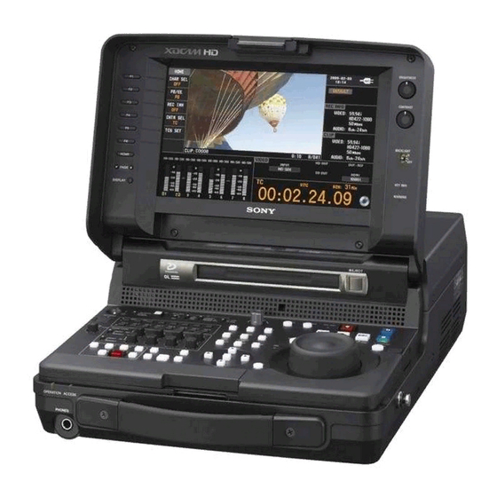
PROFESSIONAL DISC FIELD STATION
PDW-HR1
The supplied CD-ROM includes operation manuals for the PDW-HR1 Professional Disc
Field Station (English, Japanese, French, German, Italian, Spanish and Chinese
versions) in PDF format.
For more details, see "Using the CD-ROM Manual" on page 20.
OPERATION MANUAL
1st Edition (Revised 5)
[English]
Advertisement
Table of Contents

Related Manuals for Sony PDW-HR1


Summary of Contents for Sony PDW-HR1
- Page 1 PROFESSIONAL DISC FIELD STATION PDW-HR1 The supplied CD-ROM includes operation manuals for the PDW-HR1 Professional Disc Field Station (English, Japanese, French, German, Italian, Spanish and Chinese versions) in PDF format. For more details, see “Using the CD-ROM Manual” on page 20.
-
Page 2: Important Safety Instructions
The unit is not disconnected from the AC power source Important Safety Instructions (mains) as long as it is connected to the wall outlet, even if the unit itself has been turned off. • Read these instructions. • Keep these instructions. This apparatus is provided with a main switch on the rear •... - Page 3 CAUTION Use of controls or adjustments or performance of procedures other than those specified herein may result in hazardous radiation exposure. WARNING Excessive sound pressure from earphones and headphones can cause hearing loss. This Professional Disc Field Station is classified as a CLASS In order to use this product safely, avoid prolonged listening at 1 LASER PRODUCT.
- Page 4 (urban outdoors) and E4 (controlled EMC environment, ex. TV limited warranty applicable to this product. studio). The manufacturer of this product is Sony Corporation, 1-7-1 Konan, Minato-ku, Tokyo, Japan. The Authorized Representative for EMC and product safety is Sony Deutschland GmbH, Hedelfinger Strasse 61, 70327 Stuttgart, Germany.
- Page 5 ATTENTION Consignes de sécurité importantes Eviter d’exposer l’appareil à un égouttement ou à des éclaboussures. Ne placer aucun objet rempli de liquide, • Lisez ces instructions. comme un vase, sur l’appareil. • Conservez ces instructions. • Tenez compte de tous les avertissements. Ne pas installer l’appareil dans un endroit confiné, par •...
- Page 6 Ce produit est prévu pour être utilisé dans les environnements électromagnétiques suivants : E1 (résidentiel), E2 (commercial et industrie légère), E3 (urbain extérieur) et E4 (environnement EMC contrôlé ex. studio de télévision). Le fabricant de ce produit est Sony Corporation, 1-7-1 Konan, Minato-ku, Tokyo, Japon.
- Page 7 Installieren Sie das Gerät so, dass der Benutzer leicht auf den E4 (kontrollierter EMV-Bereich, z.B. Fernsehstudio) Hauptschalter zugreifen kann. Der Hersteller dieses Produkts ist Sony Corporation, 1-7-1 Konan, Minato-ku, Tokyo, Japan. Der autorisierte Repräsentant für EMV und Produktsicherheit ist Sony Deutschland GmbH, Hedelfinger Strasse 61, 70327 Stuttgart, Deutschland.
- Page 8 Важные инструкции по технике безопасности ДАННОЕ УСТРОЙСТВО ДОЛЖНО БЫТЬ • Прочитайте эти инструкции. ЗАЗЕМЛЕНО. • Сохраните эти инструкции. • Относитесь к предупреждениям с вниманием. • Следуйте всем инструкциям. ВНИМАНИЕ • Не используйте это изделие рядом с водой. Аппарат не должен подвергаться воздействию капель •...
- Page 9 1-7-1, Конан, Минато-ку, Токио, Япония, 108-0075 Сделано в ЯПОНИИ Импортер на территории стран Таможенного союза ЗАО «Сони Электроникс», Россия, 123103, Москва, Карамышевский проезд, 6 PDW-HR1 - профессиональное устройство записи на диски, поддерживающее воспроизведение и запись Full × × HD (1920 1080 и...
-
Page 11: Table Of Contents
Table of Contents Chapter 1 Overview Features..................16 Features of this unit ................16 System Configurations ..............19 Using the CD-ROM Manual ............20 Preparations ..................20 Reading the CD-ROM manual ............20 Chapter 2 Names and Functions of Parts Configuration ................. - Page 12 Discs used for recording and playback..........60 Notes on handling................60 Write-protecting discs ................. 61 Loading and unloading a disc.............. 61 Formatting a disc ................. 61 Chapter 4 Recording and Playback Recording ..................62 Mixed recording of clips in different formats on the same disc..62 Preparations for recording ..............
- Page 13 What is scene selection? ..............90 Creating and editing clip lists .............. 91 Managing clip lists................96 Disc Operations ................97 Checking disc properties..............97 Using planning metadata ..............98 Checking user-defined essence marks ..........99 Formatting discs................... 99 Displaying disc and clip properties in a web browser ....... 100 Transferring clips (Direct FTP function)........
- Page 14 Operating on files ................132 Exiting file operations ............... 133 FTP File Operations..............133 Making FTP connections..............133 Command list ..................134 Recording Continuous Timecode with FAM and FTP Connections ................139 Chapter 8 Menus Menu System Configuration ............140 Setup Menu ..................140 Items in the basic menu ..............
- Page 15 To eject discs with the unit powered off..........187 Specifications ................187 Software Downloads................190 Using UMID Data................191 Ancillary Data................193 Ancillary data in HDSDI/SDSDI signals .......... 193 Ancillary data in MXF files............... 193 General MXF metadata..............193 Closed caption data................194 List of Supported USB Keyboards..........
-
Page 16: Features
It has a compact, lightweight body for easy portability 1) MPEG HD is a registered trademark of Sony Corporation. outdoors, making it ideal for field applications and also for 2) Playback only supported for 18 Mbps. - Page 17 By checking the thumbnails, STOP operations on the camcorder. you can easily find the scene you want. 1) HDCAM is a trademark of Sony Corporation. Usability features Clip Continuous Rec function Normally, a clip is generated as an independent file every AC, DC, and battery power support time recording starts and stops.
- Page 18 202 option board is installed) operation • DVB-ASI TS input and output (when the PDBK-202 The PDW-HR1 is small and light enough to carry out into option board is installed) the field. It can be operated with batteries, allowing you to •...
-
Page 19: System Configurations
System Configurations Professional Discs PDW-HD1500 PDW-700 • PFD23A • PFD50DLA RM-280 editing controller Sony BP-L80S/GL95 battery DC power source AC power source BVE-700 Microphone SD video monitor Headphones HD video monitor HDW-2000 series Audio monitor PDW-F75 Laptop computer System Configurations... -
Page 20: Using The Cd-Rom Manual
Adobe Reader. In such a case, install the latest version you can download from the URL mentioned in “Preparations” above. Note If you have lost or damaged the CD-ROM, you can purchase a new one to replace it. Contact your Sony service representative. Using the CD-ROM Manual... -
Page 21: Configuration
Names and Functions of Parts Chapter Configuration Connector panel (see page 38) Security slot You can fit a commercially available security cable into this slot. For information about how to use Battery pack shoe (covered) your security cable, refer to the (see page 41) instructions provided with the security cable. -
Page 22: Control Panel
Control Panel The names and symbols of buttons and knobs on the Orange: Function when the button is operated with the control panel are color coded according to function. SHIFT button held down. White: Function when the button or knob is operated independently. -
Page 23: Time Data Settings Section
b On/standby ("/1) switch and indicator 1 Time data settings section When the POWER switch on the connector panel is set to the + position, and when DC power is connected to the DC IN 12V connector on the connector panel, this switches the 1 INT/EXT/SDI switch unit between the operating state (the switch is in the + 2 PRESET/REGEN switch... -
Page 24: Menu Operation Section
For details, see “Setting Timecode” (page 51). 2 Menu operation section 1 PUSH SET knob 2 MENU button 3 SAVE button 4 RESET button 5 SUB CLIP/DISC MENU button 6 S.SEL button 7 THUMBNAIL/ESSENCE MARK button 8 CHAPTER button 9 RETURN button q;... -
Page 25: Return Button
on, when you want to perform a thumbnail search or create During recording or playback, a shot mark 1 or shot mark a clip list from a GUI screen. Press it again, turning it off, 2 essence mark is recorded when you press the PUSH SET to return to full-screen display. -
Page 26: Audio Level Adjustment Section
Press it again to resume recording or playback. REF on page P1 VIDEO of the function menu) is not being input. d PREV (previous) button Press this button, turning it on, to show the first frame of This unit can automatically enter standby off mode the current clip. -
Page 27: Delete Button
d ALL/CH-1 and CH-2 to CH-4 adjustment knobs c DELETE button These knobs adjust the audio levels of channels 1 to 4 (CH- Deletes an In or Out point in a clip or sub clip. Delete the 1 to CH-4). The knobs in the upper row adjust recording point (if it exists) by holding down the IN or OUT button levels, and the knobs in the lower row adjust playback and pressing this button. -
Page 28: Entry Button
h UNDO button 6 OPERATION and ACCESS indicators Undoes the immediately preceding operation. and PHONES jack i IN (set IN point) and OUT (set OUT point) buttons This buttons light when an In or Out point is set. 1 OPERATION indicator When either button is pressed alone, the timecode of the In 2 ACCESS indicator or Out point appears. - Page 29 c CHROMA switch and adjustment knob recording to stop when this button is pressed, set setup Set the chroma signal output levels for HD and SD output. menu item 145 MODE KEY ENABLE DURING PRE: Regardless of manual settings, set the chroma signal RECORDING to “stop &...
-
Page 30: Display Panel
Display Panel 1 Function buttons (F1 to F6) 2 Control panel illumination LED 3 Display 4 CONTRAST adjustment knob 5 BRIGHTNESS adjustment knob 8 DISPLAY button qa WARNING indicator q; KEY INHI indicator 7 BPAGE and PAGEb buttons 9 BACKLIGHT switch 6 HOME button a Function buttons (F1 to F6) d CONTRAST adjustment knob... -
Page 31: Display Screen
h DISPLAY button k WARNING indicator With each press, switches the display between the basic Lights when the unit detects a hardware error such as operating screen and the video monitor. condensation inside the unit or a laser diode error. Goes out when the error condition is corrected. - Page 32 b Remaining memory capacity The following characters can be displayed as clip names in This is a popup window that display the remaining this area. capacity of the unit’s internal memory. The popup window • Digits: 0 to 9 appears only when the disc exchange cache function is •...
- Page 33 Display Description BANK2 The current menu settings are the same as the settings in menu bank 2. BANK3 The current menu settings are the same as the settings in menu bank 3. DEFAULT The current menu settings are the same as the factory defaults.
- Page 34 2 Audio input display/Audio level meters Displays information about audio. There are two display mode, which can be switched over using AU METER on modes for the audio level meter: FULL mode and FINE page P2 AUDIO of the function menu. Meter display mode: FULL Meter display mode: FINE 9 Meter display mode...
- Page 35 1) The indication and the menu items appear only when the PDBZ-UPG03 connectors, displays the formats before and after Software Upgrade Key or the PDBK-MK1 option board has been conversion and the conversion mode. installed. SQ: Squeeze mode EC: Edge-crop mode h Level bars LB: Letter box mode Display the audio recording or playback levels of channels...
-
Page 36: Time Data
f Time data 4 Time data display area Normally displays timecode or VITC, according to the selection made with TCR on page P3 TC of the function menu. 1 Time data type 2 Repeat playback mode g Memory card loaded indication and remaining 3 NDF recording capacity 4 VITC... -
Page 37: Video Monitor Display
Video monitor display Video monitor 1 Waveform monitor/Vectorscope 6 Power status 5 Time data display 4 Disc loaded indication and remaining recording capacity 3 Memory card loaded indication and remaining recording capacity 2 Audio level meters a Waveform monitor/Vectorscope b Audio level meters You can display a basic waveform monitor or a basic Displays basic audio level meters. -
Page 38: Connector Panel
Connector Panel 1 -AC IN connector 2 POWER switch 3 ANALOG AUDIO INPUT 1 to 4 connectors 4 MIC POWER (+48V) 1, 2 switches 5 ANALOG AUDIO OUTPUT 1 5 ANALOG AUDIO OUTPUT 1 to 4 connectors 6 DC IN 12V connector wa REF. - Page 39 These output HDSDI format video/audio signals. These output analog audio signals. When editing with two PDW-HR1 units, connect a cable When the unit is shipped from the factory, connectors 1 to between these connectors on the player unit and the SD/ 4 are set to audio channels 1 to 4.
- Page 40 (D-sub 9-pin) To control this unit from a controller or VTR supporting VORSICHT the RS-422A Sony 9-pin VTR protocol, connect the device • Aus Sicherheitsgründen nicht mit einem to this connector. Peripheriegerät-Anschluss verbinden, der zu starke Spannung für diese Buchse haben könnte.
-
Page 41: Preparing Power Sources
Refer to the operating battery pack. instructions for your battery charger for more For safety, use only the Sony battery packs listed below. information about how to charge the batteries. Lithium-ion battery pack: BP-L80S, BP-GL95 •... -
Page 42: Initial Setup
To remove the battery pack Initial Setup Follow the above procedure in the reverse flow. After the battery pack is removed, replace the cover of the battery pack shoe. This unit is shipped with the area of use, system frequency, Checking the remaining battery power recording format, and current date and time still unset. - Page 43 Press the V/MARK1 or v/MARK2 button (or turn the PUSH SET knob) to increment or decrement the value of the flashing digit. When you have finished making settings, press the SET function button (F5). The date, time, and time zone settings are saved, and the message “NOW SAVING...”...
-
Page 44: Connections And Settings
Connecting three PDW-HR1 units to a laptop Connections and computer via a LAN Settings PDW-HR1 Note Production of some of the peripherals and related devices described in this chapter may have been discontinued. For advice about choosing devices, please contact your Sony dealer or a Sony sales representative. -
Page 45: Connections For Cut Editing
Use of a shielded cable is recommended. PDW-HR1 (this unit) Laptop computer To S400 FAM connector i.LINK cable (not supplied) Connections for cut editing The following figure shows a cut editing system with this unit as the player. When making the connections, also refer to the manuals provided with the equipment to be connected. - Page 46 1: 75Ω coaxial cable (not supplied) HD video monitor 2: 9-pin remote control cable (not supplied) To HDSDI input connector PDW-HR1 (this unit, player) Reference video signal HDW-M2000 (recorder) BVE-700/700A (editing control unit) To HDSDI input connector HD video monitor...
- Page 47 HDW-M2000/ 1: 75Ω coaxial cable (not supplied) HD video monitor 2: 9-pin remote control cable (not supplied) To HDSDI input connector PDW-HR1 (this unit, player) Reference video signal HDW-M2000 (recorder) RM-280 (editing controller)
-
Page 48: Using In An Edit List Editing System
HDW-M2000/ M2000P unit as the player. 75Ω See page 109 for more information about edit list editing. PDW-HR1 (this unit, recorder) To HDSDI input connector HD video monitor 1: 75Ω coaxial cable (not supplied) -
Page 49: Connections For Pool Coverage
HDW-M2000/M2000P Operation Manual. Connections for pool coverage The following figure shows an example of connections for pool coverage, with the PDW-700 Professional Disc Camcorder connected. PDW-HR1 (this unit) PDW-700 To SDI OUT 1 connector To SD/HDSDI INPUT connector 75Ω coaxial cable (not supplied) -
Page 50: Synchronization Reference Signals
Synchronization Reference Signals The synchronization reference signal generator of this unit OUT REF on page P1 VIDEO of the function menu, and synchronizes to a reference signal input to the REF. on the type of the selected input signal. Video output VIDEO IN connector or to a video input signal. -
Page 51: Setting System Frequency
Setting System Setting Timecode Frequency There are the following four ways of recording timecode: Internal Preset mode: This records the output of the This unit can record and play back video at the system internal timecode generator, set beforehand to an frequencies of 59.94i, 50i, 29.97P, 25P, and 23.98P (1080) initial value. - Page 52 To set an initial timecode value Press the SET function button (F5) or the SAVE button at the instant when the current time matches the Press the CNTR SEL function button on the HOME displayed timecode. page of the function menu, and select TC. To set user bits Press the TCG SET function button (F5).
- Page 53 To record with no changes the timecode Set the INT/EXT/SDI switch to SDI and the PRESET/ REGEN switch to REGEN TC or REGEN VITC. multiplexed into a video signal input to the SD/ HDSDI INPUT connector To synchronize to the VITC timecode of a video signal input to the SD/HDSDI INPUT connector Input a SD/HDSDI signal containing LTC to the SD/ HDSDI INPUT connector.
-
Page 54: Superimposed Text Information
a Type of time data Superimposed Text Display Meaning Information Counter data TC reader timecode TC reader user bits data The video signal output from the COMPOSITE OUT TCR. VITC reader timecode connector, SDSDI OUTPUT connector, or the HDSDI UBR. VITC reader user bits data OUTPUT 2 (SUPER) connector contains superimposed TC generator timecode... - Page 55 Display Operation mode Display Name Description Block A Block B Yellow The playback condition has condition deteriorated to some degree. C.STANDBY OFF Standby off mode There are no read errors, but you should take the action described STOP Stop mode in the next section.
-
Page 56: Basic Function Menu Operations
Refer to the Maintenance Manual for an approximate Basic Function Menu guide to when it is time to replace optical heads. Operations To prevent playback conditions from deteriorating Pay attention to the following points when handling discs. • Do not open disc cartridges and touch discs directly with The function menu provides access to frequently used your hands. -
Page 57: Function Menu Settings
To clear the function menu from the screen Item Setting Basic operation display: Press the DISPLAY button to F5: TCG SET • When CNTR SEL is set to “TC” , switch to the video monitor display. displays a screen where you can set Video monitor display: After a menu operation, the menu the initial value of the timecode disappears after about four seconds. -
Page 58: P2 Audio Page
P2 AUDIO page Item Setting F3: WFM Makes settings related to display of the Item Setting waveform monitor or vectorscope. (The F1: AU INPUT Selects the audio input signal to assign waveform monitor or vectorscope appear to audio channels 1 to 8. only when the display is showing the SDI: Audio signal embedded into SDI video monitor.) -
Page 59: P4 Other Page
Item Setting Item Setting F3: PB VOL Sets the playback audio level of audio F5: PDPSET When the system frequency is set to 1080/59.94i, 1080/29.97P, or 720/ channels 5 to 8. 59.94P, presets the timecode of the A The playback audio level can be adjusted frame of the pulldown sequence. -
Page 60: Handling Discs
GUI screen. See page 87 for • PFD23A (capacity 23.3 GB) details. • PFD50DLA (capacity 50.0 GB) Sub-item 1) Professional Disc is a trademark of Sony Corporation. F1: OK Set an OK flag. F2: NG Set an NG flag. -
Page 61: Write-Protecting Discs
• If condensation forms, allow ample time to dry before When the EJECT button is pressed during recording, use. recording stops and the disc is ejected. If you do not want to eject the disc and stop recording when the EJECT button is pressed during recording, set setup menu item 145 MODE KEY ENABLE DURING RECORDING to Write-protecting discs... -
Page 62: Chapter 4 Recording And Playback
Recording and Playback Chapter Frame frequency group System frequency Recording 59.94 Hz 59.94P 59.94i This section describes video and audio recording on the 29.97P unit. 50 Hz See page 56 “Basic Function Menu Operations” in Chapter 3 for more information. 23.98 Hz 23.98P See page 140 “Menus”... -
Page 63: Carrying Out Recording
Selection of audio channels to monitor: Select with During pause, press the PAUSE button again to AUDIO MONITOR SELECT buttons. resume recording. Volume adjustment of the monitor audio: Adjust with If the disc becomes full the LEVEL knob. Recording stops and the message “Disc Full!” appears on Remote/local setting: Set the remote control switch. -
Page 64: Continuing Recording While Exchanging Discs (Disc Exchange Cache Function)
If the unit is set up to display superimposed text “C” indications in superimposed text information information (see page 54), “SHOTMARK1” or and their meanings “SHOTMARK2” appears every time you set an essence Indication Meaning mark. When Shot Mark1 or Shot Mark2 essence marks are set, “C”... -
Page 65: Recording With The Clip Continuous Rec Function
This unit enters HDSDI remote control mode, in which it convenient if you want to avoid generating a large number is controlled by command packets received via the SD/ of short clips, or if you want to record without worrying HDSDI INPUT connector. - Page 66 To cancel the clip salvage restoration cannot be guaranteed. Press the RETURN button. • When recording on the PDW-HR1 does not end successfully, you can use another XDCAM system to Notes perform a full salvage of the disc. As the other system, use the PDW-F1600, PDW-HD1500, PDW-F800, or •...
-
Page 67: Playback
The upper row of the time data display area displays the Playback original 24-frame timecode, and the lower row displays the 30-frame timecode. VITC 00:59:59:23 This section describes playback of video and audio on the PDT 00:59:59:29 unit. You can superimpose the 30-frame timecode after Before starting playback, make the following settings and pulldown on an external monitor. -
Page 68: Playback Operation
720) do not match, then the formats before and after For details of how to insert a disc, see “Loading and conversion appear in the HDSDI output conversion unloading a disc” (page 61). display (see page 35) and disc playback is cross converted automatically. - Page 69 To set a Shot Mark1 or Shot Mark2, hold down the V/ rotating the shuttle/jog dial, even when the MARK1 or v/MARK2 button and press the PUSH SET SHUTTLE/JOG and VAR/JOG buttons are not lit. knob or the SET button. You can also delete and modify essence marks from the Playback in shuttle mode Thumbnail Menu of the chapter thumbnail screen (see...
-
Page 70: Playback Operations Using Thumbnails
Playback in variable-speed mode and locking and deleting clip. This allows you to check the actual video as you work. In variable-speed mode, you can control the speed of playback in the range of –1 to +1 times normal speed. (You See “Thumbnail Operations”... -
Page 71: Chapter 5 Operations In Gui Screens
Operations in GUI Screens Chapter Overview You can perform scene searches, play the searched scenes, (The GUI screens can display European languages, and select scenes (edit clip list) in Graphical User Interface Japanese, Korean, Simplified Chinese, and Traditional (GUI) screens. The GUI screens are your gateways to discs Chinese for clip names and titles.) and the data saved on discs. -
Page 72: Information And Controls In Thumbnail Screens
Clip playback screen Clip thumbnail screen Unlit Unlit Unlit a), b) Clip list playback screen Clip list thumbnail screen Unlit a) Playback screens appear when you switch to video monitor display. Use the DISPLAY button to switch from the basic monitor display to video monitor display (see page 31). -
Page 73: Clip Thumbnail Screen
e Recording format Area of use Select Font Displayable The recording format of the selected clip is displayed as a setting setting languages combination of the following information. UC (for regions European English/European • Video format logo outside Japan) Alphabet languages •... -
Page 74: Expand Thumbnail Screen
f Lock icon f Total duration This icon appears when the clip is locked (protected) (see Displays the total duration of all sub clips in the clip list. page 88). Clips cannot be deleted and their clip information cannot be changed when this mark is Expand thumbnail screen displayed. -
Page 75: Displaying Menus
Essence mark thumbnail screen Note This screen displays thumbnails of the specified essence Shot marks can be set during recording and playback. They mark, found by searching all clips on the disc. can be deleted and moved. Rec Start essence marks are set automatically at the start of recording. - Page 76 To display the Thumbnail Menu Clip thumbnail screen To display the Thumbnail Menu, press the MENU button with a thumbnail screen displayed. To return to the original screen, press the MENU button again, or press the RETURN button. 1 MENU button 2 RETURN button 1 or 2 Thumbnail Menu of the clip thumbnail screen...
- Page 77 Item Operation/Setting Planning Metadata Properties Display the properties of the currently loaded planning metadata. Clear Planning Metadata Clear the currently loaded planning metadata from the unit’s memory. Lock or Delete All Clips Sub-item Lock All Clips Lock all clips. Unlock All Clips Unlock all clips.
-
Page 78: Gui Screen Operations
GUI screen operations 1 SUB CLIP/DISC MENU button 2 RETURN button PUSH SET knob RETURN button PREV button NEXT button 3 SHIFT button Clip list thumbnail screen Clip List:E0001 002/013 Shuttle/jog dial JOG indicator: Lit TC 00:00:00:00 TC 00:00:04:14 TC 00:00:12:04 TC 00:00:20:13 SHIFT button B button and b button... -
Page 79: Thumbnail Operations
To move from a menu level to the next Thumbnail Operations lower or higher menu level For a menu item displayed together with b or B, you can move to the next lower or higher menu level by pressing You can use thumbnail screens to display clip information the B or b button. -
Page 80: Searching With Thumbnails
When you reach a point that is close to the See “Selecting thumbnails” (page 79) for more thumbnail you want information. Put the shuttle/jog dial into jog mode (JOG indicator: lit), and then turn the dial to move the selection frame Using the expand function to find scenes in units of 1 thumbnail. - Page 81 Using the chapter function to find scenes To adjust the position of shot marks at chapter positions Sections between shot marks and Rec Start are called You can use the chapter thumbnail screen to adjust the chapters. position of shot marks (Shot Mark1 and Shot Mark2) at Rec Start essence marks are set automatically at the start of chapter positions.
-
Page 82: Playing The Scene You Have Found
Select the thumbnail that you want to cue up. Select Essence Mark Shot Mark1 Clip:C0010 010/041 Shot Mark2 Rec Start Others TC 00:23:00:25 TC 00:23:40:07 TC 00:24:45:11 TC 00:25:06:14 TC 00:25:49:23 TC 00:26:22:10 TC 00:27:19:04 TC 00:27:51:09 TC 00:28:06:09 TC 00:28:22:02 TC 00:23:34:18 TC 00:23:54:22 30 NOV 2005 13:40... - Page 83 clips to an external device using the Direct FTP function (see page 102). To filter clips See page 78 for more information about GUI screen operations. Display the clip thumbnail screen. If you want to select clips by video format, select the thumbnails of clips in that format.
-
Page 84: Selecting The Information Displayed On Thumbnails
Sequence Number: Thumbnail sequence number Item name Function Return to Upper Menu: Returns to the Thumbnail Lock or Delete All Filtered Unlock all of the filtered clips. Menu Clips >Unlock All Filtered Clips The selected information will appear at the bottom of Lock or Delete All Filtered Delete all of the filtered clips. -
Page 85: Checking Clip Properties
To select index pictures by using the expand and chapter functions After using the expand function (see page 80) or chapter function (see page 81) to find a frame, you can set that frame as the index picture of the clip. The following example explains how to do so from the expand thumbnail screen. - Page 86 To enter text using a USB keyboard or USB • Some symbols cannot be used in clip names. The keys for those symbols are disabled when you are editing a mouse clip name. You can connect a Windows USB keyboard or a Windows USB mouse to the MAINTENANCE connector (see See page 78 for more information about GUI screen...
-
Page 87: Setting Clip Flags
The keyboard icon on the software keyboard is highlighted Speed in the Disc Menu. Select the speed that works when a USB keyboard has been recognized and enabled best with the connected mouse. for use with this unit, and the mouse icon is highlighted To exit the software keyboard from a USB and a mouse pointer appears when a USB mouse has been keyboard... -
Page 88: Locking (Write-Protecting) Clips
To clear clip flags Select OK to lock all clips or Cancel to cancel it, and Carry out steps 1 to 3, selecting a clip that has a flag set, then press the PUSH SET knob. and then select “none” in step 4. To unlock a specific clip You can also use CLIP FLG on page P4 OTHER of the function menu to set and clear clip flags (see page 60). - Page 89 REC INH in HOME page of the function menu is set to A message appears asking you to confirm that you want to delete all clips. • Locked clips cannot be deleted. • If a deletion target clip is referenced by clip lists on the Select OK to execute the deletion, or Cancel to cancel disc, all of those clip lists are deleted as well.
-
Page 90: Scene Selection (Clip List Editing)
Clip lists Scene Selection (Clip List You can use the scene selection function to select clips from the clips saved on a disc and create a cut edit list Editing) called a “clip list”. Clip lists have numbers beginning with E, for example E0001. -
Page 91: Creating And Editing Clip Lists
To reedit clip lists on the disc Use the Load Clip List command to load the clip lists you Unit memory want to edit, and perform the steps 2 to 4 in the previous Current clip list t Clip list playback section. - Page 92 Add Sub Clip 017/035 Clip List (Add) 017/035 TC 00:30:25:11 TC 00:30:40:13 TC 01:01:28:25 TC 00:09:43:14 TC 00:30:25:11 TC 00:30:40:13 TC 01:01:28:25 TC 00:09:43:14 TC 00:24:24:29 TC 00:24:34:27 TC 00:24:46:22 TC 00:24:56:24 TC 00:24:24:29 TC 00:24:34:27 TC 00:24:46:22 TC 00:24:56:24 00:13:48:24 Scene Selection 00:13:48:24...
- Page 93 To add clips from the clip playback screen (quick To reorder sub clips insertion) This method allows you to decide the range to use and add See page 78 for more information about thumbnail screen that range as a sub clip while viewing the video in the clip operations.
- Page 94 Display the Thumbnail Menu. 001/034 Clip List (Trim) Select Delete Sub Clips, and then press the PUSH SET 00:13:48:24 Total 00:00:21:27 knob. 01:17:33:08 A message appears asking you to confirm the deletion. 01:17:55:05 Select OK, and then press the PUSH SET knob. 01:17:33:08 019/035 CLIP...
- Page 95 The Set Start Time Code screen appears. Disc Menu Save Clip List as... Name & Date/Sorted by Name Set Start Time Code DVD og BI... 08 AUG2007 11:50 E0003 03 AUG2007 17:51 E0004 03 AUG2007 17:51 E0005 03 AUG2007 17:51 2 2 : 3 4 .
-
Page 96: Managing Clip Lists
The current clip list returns to the unnamed state Managing clip lists “(no name)”. To load clip lists To delete clip lists The following procedure loads a clip list stored on the disc The following procedure deletes a clip list from the disc. into the unit’s internal memory as the current clip list. -
Page 97: Disc Operations
Clip lists will be displayed in the specified order the Disc Operations next time that you carry out an operation such as loading a clip list. Checking disc properties See page 78 for more information about GUI screen operations. Display the Disc Menu. Select Disc Properties, and then press the PUSH SET knob. -
Page 98: Using Planning Metadata
Select the desired planning metadata file, and then Using planning metadata press the PUSH SET knob. Planning metadata is a file that contains metadata about the The selected planning metadata file is loaded into the clips to be shot and recorded. unit’s memory, and the Planning Metadata Properties To use planning metadata, you will need to save a file in screen appears. -
Page 99: Checking User-Defined Essence Marks
When a b or B mark is displayed for an item, you can Checking user-defined essence press the B or b button to scroll the display by one marks character for each press. The V/MARK1 and v/MARK2 buttons scroll the You can display the names of user-defined Shot Mark0 to beginning and end of the string into view. -
Page 100: Displaying Disc And Clip Properties In A Web Browser
To disable the Format Disc command • User name: admin • Password: Model name (“pdw-hr1”) To prevent inadvertent disc formatting, resulting in the After the user name and password are verified, an loss of recorded data, you can disable the Format Disc XDCAM web page appears. - Page 101 items, including index picture changed marks, S the item that you want. Then click “Save” in the dialog marks, clip flag icons, and lock icons. that appears and specify the save destination. The specified data is downloaded to the specified location in your computer.
-
Page 102: Transferring Clips (Direct Ftp Function)
Transferring clips (Direct FTP function) You can transfer clips (MXF files) between this unit and Transfer direction Transfer target Function external devices over a network. This unit has an Direct Download One clip FTP function, which allows you to connect to any XDCAM device or computer with an FTP server function Note and transfer files with a few simple operations in the GUI... -
Page 103: Uploading Clips
To transfer while preserving the UMID of the • PDW-F1600 transfer source clips • PDW-HD1500 Check the “UMID Unchanged” option. • PDW-HR1 • PDW-F800 Note • PDW-700 If the remote host is a computer, clips are transferred To enable the UPnP function on this unit, set maintenance with the UMID unchanged regardless of this setting. - Page 104 Password for FTP login. (If the remote AutoIP: Auto IP addressing host is an XDCAM device, the default is function the model name, such as “pdw-hr1”.) Undefined: Nothing specified Default Gateway Default gateway a) If an XDCAM device is selected as the Device Type, then the User...
- Page 105 To check the connection on the remote host side If the remote host is an XDCAM device, check that the “NETWORK!” has appeared in the display or other status display location. The following table lists the various stages that appear in the connection status screen and describes the corresponding processing.
-
Page 106: Downloading Clips
See page 78 for more information about GUI screen operations. Display the Disc Menu. Select Download Clip via Direct FTP, and then press the PUSH SET knob. The Select Remote Host screen of the Download Clip via Direct FTP command appears. To upload part of a clip You can select part of a clip in the expand thumbnail screen or the chapter thumbnail screen and upload that... -
Page 107: Copying Clips Directly Between Xdcam Devices
Press the PUSH SET knob. Copying clips directly between The Select Remote Host screen appears. XDCAM devices Select “Hosts Discovered via UPnP”, and then press In the field or another environment where the devices are the PUSH SET knob. not connected to a network, you can copy (upload) clips between XDCAM devices by connecting them directly. -
Page 108: Shortcut List
Shortcut List You can access many functions from the buttons, without Note displaying a menu (shortcut operations). The same shortcut may access different functions, Shortcuts are available for the following functions. The depending on the screen that is active when it is executed. plus sign (+) indicates that one button is held down while another is pressed, for example “SHIFT + STOP”. -
Page 109: Chapter 6 Edit List Editing
Edit List Editing Chapter • When an edit list editing screen is displayed, signals are Overview not output from the SDSDI OUT and COMPOSITE OUT connectors. • When V INPUT on page P1 VIDEO of the function menu is set to “i.LINK” and PLAYER SEL in the Edit Edit list editing is non-destructive editing in which your Menu is set to “external”, editing cannot be performed. - Page 110 Note Each editing screen shows the display when the PDBZ- UPG03 Software Upgrade Key or PDBK-MK1 option board is installed. Clip playback screen EDIT LIST screen Clip List (Trim) screen RECALL button RETURN button PLAYER mode screen RECORDER mode screen a) You return to the clip playback screen even if you press the EJECT button to eject the disc.
-
Page 111: Parts Of The Editing Screens
PLAYER mode screen (When PLAYER SEL Parts of the editing screens is set to “disc(clip)”) EDIT LIST screen 1) When PLAYER SEL in the Edit Menu is set to “external”, the PLAYER mode screen is always full-screen display. a Clip list a Timeline Displays a list of the sub clips on the specified editing Displays along a temporal axis the clips on a disc. -
Page 112: Displaying The Edit Menu
h Viewer/thumbnail display Clip Title2: Clip title 2 Displays a thumbnail list of clips on a disc. You can use the DUR: Duration (from the start point to the end point) expand and chapter functions to expand or search inside Date: Date and time of recording the thumbnails in the thumbnail list. - Page 113 Item Operation/setting Clear Clip List Delete the current clip list. PLAYER SEL Selects the source of the clips to be used as material. disc(clip): Clips (video and audio data) on a disc inserted into the recorder external: External device disc(voice): Audio (audio data, distinct from clips) on a disc inserted into the recorder SxS: Clips (video and audio data) on an SxS memory card inserted into the recorder...
-
Page 114: Editing Screen Operations
Item Operation/setting Audio Level Sets the audio level for audio data and voice-over data. –∞, –80 dB to 0 dB to 12 dB: Can be set in units of 1 dB across the range from –∞ to 12 dB. Note This appears when the PDBZ-UPG03 Software Upgrade Key or PDBK-MK1 option board is installed. -
Page 115: Editing Operations
Editing Operations Editing modes This section explains how player materials are added to the In delete mode editing, you can delete a specified range on recorder timeline, which is editing target, in the various the recorder timeline. editing modes. Insert mode editing In insert mode editing, player material is added as sub clips The following figure shows a typical example of 3-point at specified positions on the recorder timeline. -
Page 116: Executing Edits
In point Out point Player timeline Recorder timeline In point Out point Recorder timeline (editing results) Delete mode editing In delete mode editing, all clips and audio in a specified • In delete mode editing, the EDIT PRESET setting is range on the recorder timeline are deleted. - Page 117 To select clips from a thumbnail list When there are no sub clips Switch to thumbnail display by pressing the This operation is not needed, because edit points THUMBNAIL button, and then select a clip. Next, cannot be set. press the PUSH SET knob or the SET button to return to the viewer display.
- Page 118 If you did not load an edit list in step 2, use the Save To adjust the In and Out points of sub clips Clip List as… command in the Edit Menu to save the (trim) edit list (see page 95). When two edit points or less have been set, the editing In the EDIT LIST screen, select a sub clip.
-
Page 119: Performing Voice-Over Editing
You can add narration and other voice content by To use voice-over editing functions, the PDBZ-UPG03 overlapping it with the audio of previously edited sub clips Sony Software Upgrade Key for PDW-HR1 or PDBK- (voice-over editing). MK1 option board must be installed. - Page 120 Set the following items in the Edit Menu. Note PLAYER SEL: external The maximum number of voice data sub clips that can EDIT PRESET: Voice be registered in a single edit list is 99. INPUT VOICE CH: The channel to which you have connected the microphone or other input device Play the edit segment and check the audio.
- Page 121 To perform audio split editing relative levels of audio data and voce data in this way for the whole clip. The following figure shows an example of a sub clip C0002 with the audio In point trimmed to +2 seconds after the video In point.
- Page 122 Turn the PUSH SET knob to move “p” to the channel Notes that you want to designate for mixing, and the press the • Voice data movement is done in overlay mode. If voice PUSH SET knob. data already exists at the position you move to, it is You can now turn the selected output channel on and overwritten.
-
Page 123: Chapter 7 File Operations
File Operations Chapter Overview A remote computer can be connected to this unit and used to operate on recorded data which has been saved in data files, such as video and audio data files. There are two ways to connect a remote computer. •... -
Page 124: File Operation Restrictions
FTPS protocol support Note The unit supports both the FTP and FTPS protocols Voice-over editing function is enabled when the PDBZ- (software version 3.0 and later). UPG03 Software Upgrade Key or PDBK-MK1 option The use of the FTPS protocol is recommended when using board is installed. -
Page 125: Clip Directory
Read/Partial read Write/Partial write Rename Create Delete Audio clip files (MXF files) generated b), c) b), d) P*.MXF when you execute voice over editing on the PDW-HR1 *: 0001 to 0099 Other files Files other than the above – – –... -
Page 126: Edit Directory
• Voice-over editing function is enabled when the PDBZ- Notes UPG03 Software Upgrade Key or PDBK-MK1 option • Directories cannot be created in the Component board is installed. directory. Edit directory File name Content Operations Read/Partial read Write/Partial write Rename Create Delete Clip list file E01.SMI *: 0001 to 0099... -
Page 127: Assigning User-Defined Clip Titles
General directory File name Content Operations Read/Partial read Write/Partial write Rename Create Delete Any file a) UTF-8 file names can be up to 63 bytes in length. (Depending on the character type, file names (including extension) may be limited to 21 characters.) The following directory operations are possible in the General directory. -
Page 128: Assigning User-Defined Clip And Clip List Names
Turn the PUSH SET knob to select “enable”, and press Assigning user-defined clip and clip the knob. list names The automatic title generation function is enabled. The following standard format names are assigned Turn the PUSH SET knob to move the asterisk (*) on automatically to clips and clip lists that are created or the left of the menu items to the item you want to recorded by XDCAM devices. - Page 129 Command prompt FTP commands do not support Turn the PUSH SET knob to move the “*” to the left UTF-8. of “AUTO NAMING”, and press the knob. Turn the PUSH SET knob to select “title”, and press the knob. Press the SAVE function (F5) button. C0001.MXF The same name will now be given to newly recorded clips.
-
Page 130: File Operations In File Access Mode (For Windows)
Making FAM connections File Operations in File Access Mode (for If there is a disc loaded in this unit, put the unit into the following state. Windows) • Recording, playback, search and other disc operations (see page 62): Stopped • THUMBNAIL/ESSENCE MARK button (see File access mode operating environment page 24): Off Operating system requirements for file operations by file... -
Page 131: Operating On Files
“Eject Solid state disk”. • All file operations are not possible for some types of files. “The ‘Sony XDCAM PDW-HR1 IEEE 1394 SBP2 Device’ device can now be safely removed from the For details, see “File operation restrictions”... -
Page 132: File Operations In File Access Mode (For Macintosh)
Press the PC REMOTE button, lighting it. (This File Operations in File enables remote access (see page 23).) When a disc is inserted into this unit, the remote Access Mode (for computer recognizes this unit as a removable disc. The Macintosh) following icon appears in the Finder on the remote computer, indicating that the computer is now able to... -
Page 133: Exiting File Operations
Exiting file operations FTP File Operations Proceed as follows. File operations between this unit and a remote computer Note can be carried out by the File Transfer Protocol (called Do not disconnect the cable before performing steps 1 and FTP below). Preparations Eject the disc by clicking the eject button to the right of the icon for this unit in the Finder, or by dragging... -
Page 134: Command List
Enter the password and press the Enter key. Command syntax: QUIT <CRLF> The password is set to “pdw-hr1” when the unit is shipped from the factory. PORT The login is complete when the password is verified. - Page 135 • p1 (most significant byte), p2 (least significant byte): Port <mode-code> can be any of the following. However, for address XDCAM, the mode is always “S”, regardless of the mode- code specification. Input example: PORT 10,0,0,1,242,48 • S: Stream mode (default) (IP address: 10.0.0.1, Port number: 62000) •...
- Page 136 RETR DELE Begins transfer of a copy of a file in the specified path on Deletes the specified file on this unit. this unit to the current directory on the remote computer. Command syntax: RETR <SP> <path-name> <CRLF> Note Input example: RETR Clip/C0001.MXF Depending on the directory and file type, deletion may not be possible.
- Page 137 The following data is transferred, depending on whether a Command syntax: RMD <SP> <path-name> <CRLF> command name is specified with <command-name>. • Command name specified: Explanation of the specified Extended commands command. The following table shows the extended FTP commands •...
- Page 138 Input example: SITE REPFL “Clip/sakura 0001.MXF” 5 150 • When a file in the General directory is specified in <path- name> (Transfer sakura 0001.MXF. Body data is transferred - 444: Forbid writing to and execution of the file. only from frame 6 to frame 150.) - 555: Forbid writing to the file, but allow execution.
-
Page 139: Recording Continuous Timecode With Fam And Ftp Connections
Recording Continuous Timecode with FAM and FTP Connections When you are connected to the unit by FAM or FTP, you can create new clips with timecode that is continuous with the timecode of the last frame of the last clip on the disc. To record continuous timecode, set the INT/EXT/SDI switch to “INT”, and set the PRESET/REGEN switch to “REGEN TC”. -
Page 140: Chapter 8 Menus
Menus Chapter Menu System Setup Menu Configuration The setup menu system of this unit comprises the basic setup menu and extended setup menu. The settings for this unit use the following menus. Basic menu Setup menu This menu is used to make settings relating, for example, The setup menu system of this unit comprises the basic to the following. -
Page 141: Items In The Basic Menu
Item group Function Refer to Item group Function Refer to Items Settings relating to the page 152 Items Settings relating to control page 148 600 to 650 timecode generator 100 to 199 panels Items Settings relating to the page 153 Items Settings relating to the remote page 150... - Page 142 Item number Item name Settings DISPLAY INFORMATION Determine the kind of text information to be output from the COMPOSITE SELECT OUT connector, the SDSDI OUTPUT connector, or the HDSDI OUTPUT 2 (SUPER) connector. T&sta (time data & status): Time data and the units status. T&UB (time data &...
- Page 143 Item number Item name Settings SYSTEM FREQUENCY Specify whether to enable switching the system frequencies (59.94i, 59.94P, SELECT MENU 29.97P, 50i, 50P, 25P, 23.98P). off: Do not enable switching the system frequencies. on: Enable switching the system frequencies. For details about switching the system frequencies, see page 51. Note Settings for both basic and extended menu items are saved separately for different system frequencies.
- Page 144 Item number Item name Settings STORED OWNERSHIP Specify whether to enable changing UMID ownership information settings (COUNTRY, ORGANIZATION and USER). off: Do not enable. on: Enable. See “Using UMID Data” (page 191) for more information about UMID. RECORDING FORMAT Set the recording format. HD422: HD422 420HQ (HD420 HQ): HD420HQ 420SP (HD420 SP): HD420SP...
-
Page 145: Basic Menu Operations
Item number Item name Settings RESET SETUP MENU Set to “on” to return the settings of the current menu to the factory default settings. Set to “bank-4” to set the current menu to the settings saved in menu bank 4. on: Return the current menu to the factory default settings. -
Page 146: Default Settings
To change other settings, press the PUSH SET knob or Menu control Functions the SELECT function button (F2) to return to the buttons previous screen, then repeat steps 1 to 3. Function buttons RETURN: Goes up one level. F1 to F6 SELECT: Selects an item. - Page 147 Press the PUSH SET knob. Note A setting screen for the currently selected item If you power off the unit while settings are being appears. saved, settings may not be correctly returned to their factory default settings. Wait until the saving is completed before powering off the unit.
-
Page 148: Items In The Extended Menu
Items in the extended menu The following tables show the items in the extended menu. • The values in the Settings columns are the values which • Item names are the names which appear on an external appear in the time data display area. (The values may monitor to which the output of the COMPOSITE OUT appear in a different format on an external monitor. - Page 149 Menu items in the 100s, relating to the control panels (OPERATIONAL PARAMETER) Item number Item name Settings AUDIO VOLUME Select whether each of the ALL/CH-1 and CH-2 to CH-4 adjustment knobs on the control panel is enabled, allowing you to adjust the audio recording and playback levels of each channel individually, or whether the ALL/CH-1 adjustment knob alone functions as a master control to Sub-item...
- Page 150 Menu items in the 100s, relating to the control panels (OPERATIONAL PARAMETER) Item number Item name Settings FIND MODE Specify the frame to be cued up when the PREV or NEXT button is pressed. clip: The first frame of the clip R.ST (clip &...
- Page 151 Menu items in the 300s, relating to editing operations (EDITING) Item number Item name Settings SELECTION OF STD/NON-STD Select the STD or NON-STD mode in accordance with a composite FOR COMPOSITE VIDEO IN video input. STD (forced STD): The STD mode is always used (forced STD mode). N-STD (forced non-STD): Use this setting when the input video signal is unstable (forced NON-STD mode).
- Page 152 Menu items in the 500s, relating to disc protection (DISC PROTECTION) Item number Item name Settings STILL TIMER To protect the disc against shock and vibrations, and to lengthen the life of the laser diodes, the unit automatically enters standby off mode whenever a specified time elapses in a disc stop mode (stop mode or the still picture mode of search mode).
- Page 153 Menu items in the 600s, relating to the timecode, metadata, and UMID (TIME CODE GENERATOR/META DATA) Item number Item name Settings U-BIT BINARY GROUP FLAG Select the user bits to be used in the timecode generated by the timecode generator. 000 (000:not specified): Character set not specified.
- Page 154 Menu items in the 600s, relating to the timecode, metadata, and UMID (TIME CODE GENERATOR/META DATA) Item number Item name Settings UMID HD VANC LINE Select the line in which UMID is output when menu item 651 is set to “on”.
- Page 155 Menu items in the 700s, relating to video control (VIDEO CONTROL) Item number Item name Settings BLANK LINE SELECT Switch blanking of the video output signal on or off for individual lines in the vertical blanking interval. Sub-item The Y/C signal and odd/even fields are blanked simultaneously. ALL LINE - - -: Specify the blanking for each line separately.
- Page 156 Menu items in the 700s, relating to video control (VIDEO CONTROL) Item number Item name Settings VIDEO SETUP REFERENCE Set the video setup amount to be added to the composite input and output signal (in 59.94i/59.94P/29.97P mode only). Sub-item INPUT LEVEL 59.94i/59.94P/ Remove the setup level selected by this item frrom the input signal.
- Page 157 Menu items in the 700s, relating to video control (VIDEO CONTROL) Item number Item name Settings WIDE MODE Specify whether to record and play back with the addition of wide picture information. Sub-item INPUT Select whether to save wide picture information to the disc when recording.
- Page 158 Menu items in the 800s, relating to audio control (AUDIO CONTROL) Item number Item name Settings DIGITAL AUDIO MUTING IN Set the audio muting conditions during shuttle playback. SHUTTLE MODE off: Not muted. on: Muted. AUDIO OUTPUT PHASE Set the output timing of digital audio playback signals (HDSDI, SDI only), with 80H as a reference position.
- Page 159 Menu items in the 800s, relating to audio control (AUDIO CONTROL) Item number Item name Settings AUDIO INPUT LEVEL Select the analog audio input source. Sub-item line: Line input mic: Microphone input line: Line input mic: Microphone input line: Line input mic: Microphone input line: Line input mic: Microphone input...
- Page 160 Menu items in the 800s, relating to audio control (AUDIO CONTROL) Item number Item name Settings AUDIO OUTPUT ARRANGE Specify the mixing of audio/voice data output signals. Note This appears when the PDBZ-UPG03 Software Upgrade Key or PDBK- MK1 option board is installed. See “To set up mixing of audio/voice data output signals”...
- Page 161 Menu items in the 900s, relating to digital process (DIGITAL PROCESS) Item number Item name Settings V-FILTER SELECT (DC) Set the vertical interpolation filter coefficient for down-converter output (in 1080 mode only). If the setting value is large, the vertical resolution is high. 1 (1 (DEC)) to 3 (3 (DEC)) CROSS COLOR CRISP (DC) Set the cross color crisp level for down-converter output.
-
Page 162: Extended Menu Operations
Menu items in the 900s, relating to digital process (DIGITAL PROCESS) Item number Item name Settings IMAGE ENHANCER (INPUT UP Set up the operation of the up converter image enhancer for SD input, CONVERTER) separately from the settings for playback (menu items 950 to 959). Sub-item ENH SETTING pb: While SD signals are input, make the behavior of the image... - Page 163 M A I N T E N A N C E M E N U M 0 : C H E C K M 1 : A D J U S T M 2 : S E R V I C E S U P P O R T M 3 : O T H E R S M 4 : S E T U P M A I N E N A N C E M 5 : N E T W O R K...
-
Page 164: Maintenance Menu
Maintenance Menu Items in the maintenance menu The following tables show the items in the maintenance appear in a different format on an external monitor. In menu. this case, the external monitor values are shown in • Item names are the names which appear on the video parentheses.) Underlined values are the factory defaults. - Page 165 M3: OTHERS: Other setting items Item Setting M37: AUDIO M370: HEAD ROOM Select the audio reference level (headroom). CONFIG –20dB, –18dB, –16dB, –12dB, EBUL Note EBUL can be selected only when the system frequency is 50i/50P/25P. M371: DATA LEN Select the audio channel configuration for IMX recording. 16bit ×...
- Page 166 M3: OTHERS: Other setting items Item Setting M3B: VANC RX M3B0: VANC RX For setting HDSDI VANC data input parameters PARAMETER PACKET Notes • In 59.94i, 50i, 29.97P or 25P mode, selecting the line also selects the corresponding line in the second field (for example, if line 9 is selected, line 572 is also selected for VANC packet reception).
- Page 167 M4: SETUP MAINTENANCE: Items relating to the setup menu Item Setting M46: MENU M461: MENU Displays the status of the menu bank where the current menu settings are stored. DATA STATUS DISP CONTROL M462: SAVE Select whether to temporarily back up (save) setup menu settings before operations such as MENU DATA software upgrades.
-
Page 168: Maintenance Menu Operations
M5: NETWORK: Items relating to network settings Item Setting M55: DUPLEX Set the communications method. AUTO, Full Duplex, Half Duplex For how to set the communication method, see “To change network settings” (page 169). Set the size of jumbo frames. M56: JUMBO FRAME 9014, 4088, OFF(1514) Note... - Page 169 To change a menu item setting To change network settings Carry out the following operations to change the setting. To change network settings, carry out the procedure described in the previous section, “To display the For information about how to change network settings see maintenance menu”, to display the NETWORK menu next section “To change network settings”.
- Page 170 Press the PUSH SET knob or use the V/MARK1 or v/ This returns to the NETWORK menu. MARK2 button to select a communications protocol. Repeat steps 1 to 4 as required, to set the subnet mask and default gateway. To return to the factory default setting Press the RESET button.
-
Page 171: Chapter 9 Planning Metadata
• To sort planning metadata • Extension: XML • To check planning metadata properties a) General/Sony/Planning directory is created automatically when a disc is • To clear planning metadata formatted. Automatically when a disc is formatted. • To switch the title display in the video monitor screen Note See “Using planning metadata”... -
Page 172: Setting Essence Mark Names By Using Planning Metadata
<PlanningMetadata xmlns="http:// • Serial numbers are not reset when you power the unit off xmlns.sony.net/pro/metadata/ or exchange discs (newly generated numbers are planningmetadata" assignId=" continuous on the old ones). P0001" creationDate=" • If the ASCII format clip name string is longer than 14 2008-01-20T17:00:00+09:00"... -
Page 173: Setting Volume Labels By Using Planning Metadata
" "/>3 <Meta name="_ShotMark6" content= Foul " "/>3 Example volume label specification <Meta name="_ShotMark7" content= <?xml version="1.0" encoding="UTF-8"?>3 " "/>3 <PlanningMetadata xmlns="http://xmlns.sony.net/pro/ <Meta name="_ShotMark8" content= metadata/planningmetadata" assignId="H00123" 1st Half " "/>3 creationDate="2010-01-27T08:00:00Z" lastUpdate= <Meta name="_ShotMark9" content= "2010-01-27T15:00:00Z" version="1.00">3 2nd Half "... -
Page 174: Appendix
If it appears, wait until it disappears before inserting a In the event of operating problems disc. If you should experience problems with the unit, contact a Sony service representative. About the LCD panel Use and storage locations LCD panels are manufactured with extremely high Store in a level, ventilated place. -
Page 175: Periodic Maintenance
Use the information as a guide in scheduling periodic maintenance. For periodic maintenance, consult a Sony service representative. Display modes of the digital hours meter H01: OPERATION mode Displays the total number of hours the unit has been powered on in units of 1 hour. -
Page 176: Note About The Battery Terminal
Periodic inspections are recommended to keep the unit working properly and to prolong its usable lifetime. Contact a Sony service or sales representative for more information about inspections. Periodic Maintenance... -
Page 177: Troubleshooting
Reset the settings in the setup menu (see MENU. page 146). If the same message appears after SET ITEMS IN THE SETUP MENU TO THE you reset the settings, contact a Sony service APPROPRIATE VALUES. CONTACT SERVICE representative. IF THIS ALARM APPEARS AGAIN AFTER ABOVE PROCEDURE. - Page 178 When a disc is inserted Alarm message in time Alarm message in video monitor screen Description/action data display area Unknown FS! UNKNOWN FILE SYSTEM. Format the disc, or eject it (see page 99). PLEASE FORMAT DISC OR EJECT. No FS! NO FILE SYSTEM.PLEASE EJECT DISC.
- Page 179 Alarm message in time Alarm message in video monitor screen Description/action data display area REMOTE MODE IS SELECTED. Set the remote control switch to “LOCAL”. REMOTE! SET REMOTE/LOCAL/NETWORK SWITCH TO LOCAL. NO DISC. Insert a disc and try again. No Disc! REC INHI.! AUTO FORMATTING WAS NOT Set the disc’s Write Inhibit tab to enable recording...
- Page 180 Alarm message in time Alarm message in video monitor screen Description/action data display area COUNTER MODE IS SELECTED. This appears when CNTR SEL on the HOME page of CNT mode! SET COUNTER SELECT MENU TO TC the function menu is set to “COUNTER”, and you try OR UB.
- Page 181 Alarm message in time Alarm message in video monitor screen Description/action data display area No EM space ESSENCE MARK NOT RECORDED. Delete unneeded shot marks in the chapter thumbnail NO SPACE AVAILABLE TO RECORD screen. ESSENCE MARK. EM Full! NO MORE ESSENCE MARKS CAN BE RECORDED.
-
Page 182: During Playback
Alarm message in time Alarm message in video monitor screen Description/action data display area INPUT VIDEO SIGNAL DOES NOT Input a reference signal synchronized with this unit’s ILL. REF! SYNCHRONIZE WITH REF VIDEO system frequency. SIGNAL. USE COMMON REFERENCE SIGNAL OR CONNECT RECORDER REF OUT TO PLAYER REF IN. - Page 183 Alarm message in GUI Description/action screen CHAPTER DOES NOT The specified chapter has not been recorded. EXIST. This appears when an attempt is made to display a chapter when a chapter has not been recorded for that clip. SOME ESSENCE MARK The Rec Start essence mark cannot be deleted.
- Page 184 Alarm message in GUI screen Description/action AUTOEDIT WAS NOT COMPLETED. An auto edit failed for a reason other than those described above. This appears when the specifications of this unit are exceeded. For example, the specifications do not allow more than 300 clips to be recorded on one disc, and do not allow the total duration of sub clips to exceed 24 hours.
- Page 185 Alarm message in time Alarm message in video monitor screen Action data display area FAN Stopped FAN MOTOR STOPPED. Contact a Sony service representative. Note DR-FAN Stop DRIVE FAN MOTOR STOPPED. The unit will not stop operating, but if you continue to High TEMP! HIGH TEMPERATURE.
-
Page 186: Error Messages
Alarm message in time Alarm message in video monitor screen Action data display area Unknown USB UNKNOWN USB DEVICE. The USB connector of this unit is for maintenance purposes and connection of USB devices. Connect a compatible USB device. Alarms related to system frequency and recording format The following alarms are displayed only when setup menu item 016 ALARM DISPLAY is set to “on”... -
Page 187: To Eject Discs With The Unit Powered Off
Error code Specifications Error code in time data display area General External dimensions (w/h/d, including projections) ERROR 300×146.5×420 mm AN ERROR HAS BEEN ×5 ×16 inches) DETECTED. INFORM SERVICE OF FOLLOWING CODE: 50-010 PRESS EJECT KEY TO EJECT DISC. Error code Example error in video monitor screen To eject discs with the unit powered As an emergency measure, disc cartridges can be removed... -
Page 188: Processor Adjustment Range
Search speed Proxy video MPEG-4 Audio 24 bits, 48 kHz, 8 channels Jog mode –3 to +3 times normal speed Proxy audio A-law 8 bits, 8 kHz, 8 channels Variable-speed mode –1 to +1 times normal speed MPEG HD Shuttle mode –20 to +20 times normal speed Video MPEG HD: HQ35/SP25/LP18 Mbps... - Page 189 Analog video inputs AUDIO MONITOR R, L (also function as the ANALOG REF.VIDEO IN AUDIO OUTPUT 3, 4 connectors, as BNC type (×1), selected by setup menu item 820) HD Tri-level sync (0.6 Vp-p/75 Ω/ XLR 3-pin, male (×2), +4 dBu, 600 Ω, sync negative), SD black burst, or SD low impedance, balanced composite sync (0.286 Vp-p/75 Ω/...
-
Page 190: Software Downloads
BP-GL95 Battery Pack PDBK-202 MPEG TS Board PDBK-MK1 SxS Memory Card Adaptor for PDW-HR1 Design and specifications are subject to change without notice. Notes • Always make a test recording, and verify that it was recorded successfully. SONY WILL NOT BE... -
Page 191: Using Umid Data
Using UMID Data What is a UMID? Metadata is additional information recorded on discs along with audio-visual data. It is used to bring greater efficiency A UMID (Unique Material Identifier) is a unique i- to the flow of operations from material acquisition through dentifier for audio-visual material defined by the editing, and to make it easier to find and reuse material. - Page 192 About the UMID ownership information • Recording with UTC time. UTC (coordinated universal time) is used when recording the UMID. Use of a COUNTRY (country code) universal time system enables uniform management of Set the country code by entering an abbreviated source material recorded all over the world.
-
Page 193: Ancillary Data
- LINE (line for the VANC to be received): 9LINE Ancillary Data (example) - DID (data identification word): 61h - SDID (secondary data identification word): 01h • V INPUT on function menu page P1 VIDEO: SDSDI This unit can play and record ancillary data multiplexed •... -
Page 194: Closed Caption Data
For details, see “Directory structure” (page 123) and “Clip directory” (page 125). Closed caption data This section explains the closed caption data that can be recorded, played back, and output during EE output. Normal EIA-708/608 recording and playback In response to closed caption input data that complies with EIA-708/608 standard closed caption data recorded in HD the EIA-708/608 standards, record, play, and output that video is output as HDSDI signals, regardless of menu... - Page 195 EIA-708/608 EE output In response to closed caption input data that complies with Closed caption data in SDSDI line 21 signals are output to the EIA-708/608 standard, output to EE. EE (output as SDSDI or composite signals), regardless of However, settings are required for EE output of closed menu settings.
-
Page 196: List Of Supported Usb Keyboards
List of Supported USB Keyboards When the area of use is set to “UC” and Select the corresponding language by selecting Settings >Select USB Keyboard Language in the Disc Menu (see the font setting is “European Alphabet” page 86). On this unit, you can enter any of the characters and symbols supported by the keyboards listed below. - Page 197 Italian [Italy] Polish (Programmers) [Poland] Russian [Russia] Spanish [Spain] When the area of use is set to “UC” and the font setting is “Korean” The keyboard is fixed as the Korean keyboard, and you can enter Hangul characters. Note The keyboard language cannot be changed. List of Supported USB Keyboards...
- Page 198 When the area of use is set to “J” (for Notes Japan) • The keyboard language cannot be changed. The keyboard is fixed as the Japanese keyboard. • It is not possible to enter Japanese hiragana, katakana, and kanji. List of Supported USB Keyboards...
-
Page 199: Trademarks And Licenses
About IJG (Independent JPEG Trademarks and Licenses Group) This software is based in part on the work of the MPEG-4 visual patent portfolio Independent JPEG. license Character display software “iType” THIS PRODUCT IS LICENSED UNDER THE MPEG-4 VISUAL PATENT PORTFOLIO LICENSE FOR THE This product includes technology from Monotype Imaging PERSONAL AND NON-COMMERCIAL USE OF A ®... -
Page 200: About Libupnp
About OpenSSL On the basis of license contracts between Sony and the software copyright holders, this product uses open software. To meet the requirements of the software copyright holders, Sony is obligated to inform you of the content of these licenses. - Page 201 /* ==================================================================== * Copyright (c) 1998-2011 The OpenSSL Project. All rights reserved. * Redistribution and use in source and binary forms, with or without * modification, are permitted provided that the following conditions * are met: * 1. Redistributions of source code must retain the above copyright * notice, this list of conditions and the following disclaimer.
- Page 202 /* Copyright (C) 1995-1998 Eric Young (eay@cryptsoft.com) * All rights reserved. * This package is an SSL implementation written * by Eric Young (eay@cryptsoft.com). * The implementation was written so as to conform with Netscapes SSL. * This library is free for commercial and non-commercial use as long as * the following conditions are aheared to.
-
Page 203: About Pcre-8.21
About pcre-8.21 PCRE LICENCE ------------ PCRE is a library of functions to support regular expressions whose syntax and semantics are as close as possible to those of the Perl 5 language. Release 8 of PCRE is distributed under the terms of the "BSD" licence, as specified below. -
Page 204: About Jsencrypt-Master.zip
Contributed by: Google Inc. Copyright (c) 2007-2011, Google Inc. All rights reserved. THE "BSD" LICENCE ----------------- Redistribution and use in source and binary forms, with or without modification, are permitted provided that the following conditions are met: * Redistributions of source code must retain the above copyright notice, this list of conditions and the following disclaimer. - Page 205 OF CONTRACT, TORT OR OTHERWISE, ARISING FROM, OUT OF OR IN CONNECTION WITH THE SOFTWARE OR THE USE OR OTHER DEALINGS IN THE SOFTWARE. CONTAINS CODE FROM YUI LIBRARY SEE LICENSE @ http://yuilibrary.com/license/ The 'jsrsasign'(RSA-Sign JavaScript Library) License Copyright (c) 2010-2013 Kenji Urushima Permission is hereby granted, free of charge, to any person obtaining a copy of this software and associated documentation files (the "Software"), to deal in the Software without restriction, including without limitation the rights...
-
Page 206: About Cryptojs V3.1.2.Zip
* In addition, the following condition applies: * All redistributions must retain an intact copy of this copyright notice * and disclaimer. Address all questions regarding this license to: Tom Wu tjw@cs.Stanford.EDU ASN.1 JavaScript decoder Copyright (c) 2008-2013 Lapo Luchini <lapo@lapo.it> Permission to use, copy, modify, and/or distribute this software for any purpose with or without fee is hereby granted, provided that the above copyright notice and this permission notice appear in all copies. -
Page 207: Glossary
SDSDI signal A sync signal defined in SMPTE- Glossary 274M with positive, negative, and SD Serial Digital Interface. An zero values. interface standardized as SMPTE- 259M which enables the HDSDI signal transmission of an uncompressed Clip Abbreviation of HD Serial Digital digital component stream. - Page 208 VBID (Video Blanking ID) This is a video ID signal, defined in the EIAJ CPR-1204 standard, which is inserted into VBS video output to enable the aspect ratio to be detected. The ID signal is inserted into line 20, VBI 283. Glossary...
-
Page 209: Index
continuous playback mode 67 DELETE button 27 Index deleting 88 Delete Clip 89 duration 73 Delete Clip & Clip List 89 finding 80 Delete mode editing 116 locking 88 Digital hours meter 175 playback screen 71 display modes 175 AC IN connector 38 properties 85 displaying 175 ACCESS indicator 22, 28... - Page 210 thumbnail screen 74 Glossary 207 Menu EXPAND button 25 GOTO button 27 bank setting 144 Extended menu 140 GUI screens 71 changing settings 146 items 148 operations 78 configuration 140 operations 162 disc menu 76 External synchronization 50 edit menu 112 EXT-LOCK 36 function menu 56 HDMI OUT connector 40...
- Page 211 Playback condition Scrollbar 73 using thumbnails 80 display 55 SD/HDSDI INPUT connector 39 THUMBNAIL/ESSENCE MARK mark 55 SDSDI OUTPUT connector 40 button 24 PLAYER and RECORDER buttons SDSDI output conversion display 35 TIME CODE IN/OUT connectors 40 Security slot 21 Time data 36 PLAYER mode screen 111 Select Essence Mark screen 81...
- Page 212 Index...
- Page 213 The material contained in this manual consists of information that is the property of Sony Corporation and is intended solely for use by the purchasers of the equipment described in this manual. Sony Corporation expressly prohibits the duplication of any...
- Page 214 Sony Corporation PDW-HR1 Printed in Japan (SYL) 2015.08 32 4-135-245-06 (1) © 2009 Printed on recycled paper.
Need help?
Do you have a question about the PDW-HR1 and is the answer not in the manual?
Questions and answers