Icom IC-910H Instruction Manual
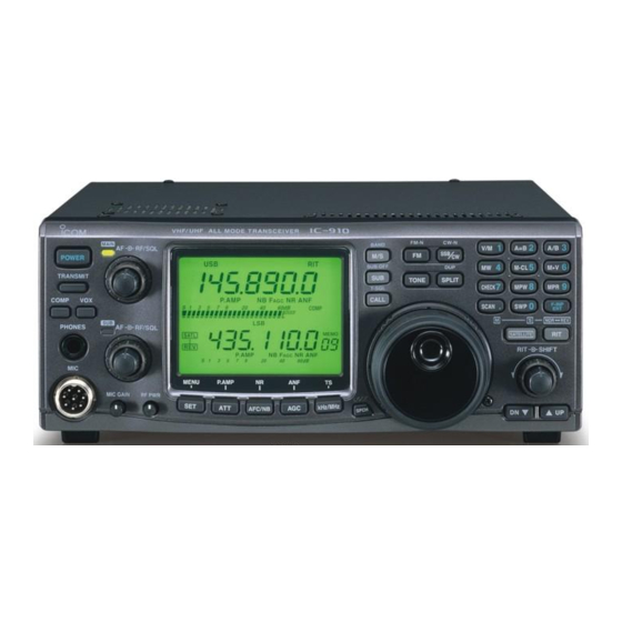
Vhf/uhf all mode transceiver
Hide thumbs
Also See for IC-910H:
- Service manual (144 pages) ,
- Instruction manual (88 pages) ,
- Programming manual (25 pages)

Subscribe to Our Youtube Channel
Related Manuals for Icom IC-910H


Summary of Contents for Icom IC-910H
- Page 1 INSTRUCTION MANUAL VHF/UHF ALL MODE TRANSCEIVER i910H From The N3UJJ.COM Document Library From The N3UJJ.COM Document Library...
-
Page 2: Explicit Definitions
AVOID placing the transceiver in excessively dusty en- Other manufacturer’s microphones have different pin vironments or in direct sunlight. assignments, and connection to the IC-910H may damage the transceiver. AVOID placing the transceiver against walls or putting anything on top of the transceiver. This will obstruct heat dissipation. -
Page 3: Table Of Contents
TABLE OF CONTENTS I Indications during transmit ... 32 IMPORTANT ........i 10 SET MODE ......55 – 69 I FM mode operation ...... 33 I Set mode description ....55 EXPLICIT DEFINITIONS ..... i I VOX operation ......33 I General set mode ...... -
Page 4: Panel Description
Push to select transmitting or receiving. Adjusts microphone input gain. e COMPRESSION SWITCH [COMP] (p. 36) Recommended level for Push to switch the speech compressor function ON an Icom microphone and OFF. MIC GAIN • The speech compressor increases average RF output Decreases Increases power, improving signal strength and readability in SSB. -
Page 5: From The N3Ujj.com Document Library From The N3Ujj.com Document Library
PANEL DESCRIPTION o MAIN BAND INDICATOR [MAIN] • When functioning as squelch control ➥ Lights green while the squelch is opened or a sig- (RF gain is fixed at maximum.) nal is received on the MAIN band; lights red while Noise squelch transmitting on the MAIN band. -
Page 6: From The N3Ujj.com Document Library From The N3Ujj.com Document Library
PANEL DESCRIPTION I Front panel (continued) !4 AF CONTROL [AF] (inner control) DO NOT connect any equipment, such as an SWR Varies the audio output level from the speaker for or power meter between the transceiver and pream- the SUB band. plifier. -
Page 7: From The N3Ujj.com Document Library From The N3Ujj.com Document Library
PANEL DESCRIPTION !8 AUTO GAIN CONTROL•AUTO NOTCH FILTER @2 BRAKE ADJUSTMENT SCREW SWITCH [AGC•ANF] Adjust the tension of the tuning dial. ➥ Push to switch the time constant of the • Rotate clockwise to increase the tension; counterclock- wise to decrease the tension. automatic gain control to SLOW and FAST for the MAIN band.* (p. -
Page 8: From The N3Ujj.com Document Library From The N3Ujj.com Document Library
PANEL DESCRIPTION I Front panel (continued) SHIFT SHIFT SHIFT @4 RIT CONTROL [RIT] (p. 27) Shifts the receive frequency without changing the transmit frequency for the MAIN band only while the RIT function is activated. • SSB/CW mode : ±1.0 kHz* in 10 Hz step •... -
Page 9: From The N3Ujj.com Document Library From The N3Ujj.com Document Library
PANEL DESCRIPTION Switch Switch action when pushed Switch action when pushed for 1 sec. • Enters numeral “1” when entering an operating frequency. (p. 23) • Switches between VFO and memory mode. (p. 40) Enters numeral “2” when entering an operating Equalizes the condition of the VFO A and B. -
Page 10: From The N3Ujj.com Document Library From The N3Ujj.com Document Library
PANEL DESCRIPTION I Front panel (continued) #5 #4 #3 #2 #1 #0 @9 1200 MHz band operation. @9 SPLIT•DUPLEX SWITCH [SPLIT•DUP] #2 TONE SWITCH [TONE] ➥ Push to turn the split function, with the ➥ Push to turn the tone encoder function VFO A and B, ON and OFF. -
Page 11: From The N3Ujj.com Document Library From The N3Ujj.com Document Library
PANEL DESCRIPTION #4 SUB•SUB OFF SWITCH [SUB•SUB OFF] ➥ Push to enable the SUB band control from the tuning dial, keypad, etc. (p. 19) • “SUB” indicator appears. ➥ Push for 1 sec. to turn the SUB band readout indication ON and OFF. (p. 24) For 1 sec. -
Page 12: I Function Display
PANEL DESCRIPTION I Function display FMN USB USB LSB CW N SPLIT SPLIT VFO A VFO B MEMO T-SQL ATT P.AMP AFC NB F NR ANF B L A N K 60dB COMP 9600 O V E R SCAN C W N VFO A VFO B MEMO... -
Page 13: From The N3Ujj.com Document Library From The N3Ujj.com Document Library
PANEL DESCRIPTION !1 DATA TRANSMISSION SPEED INDICATOR @4 TONE SQUELCH INDICATOR (pgs. 30, 34) (p. 52) “T” appears when the tone encoder function is acti- Appears when 9600 bps speed is selected for vated; “T-SQL” appears when the tone squelch packet transmission. -
Page 14: I Rear Panel
PANEL DESCRIPTION I Rear panel q 430(440) MHz ANTENNA CONNECTOR (p. 15) u KEY JACK [KEY] (p. 15) Accepts a 50 Ω antenna with a type-N connector. Accepts a paddle, a straight key or external elec- tronic keyer with ⁄ inch standard plug. -
Page 15: Panel Description
PANEL DESCRIPTION D ACC SOCKETS ACC(1) Socket Pin No. Pin Name Description Specification No connection. Connect to ground. Input terminal to transmit the trans- Transmit voltage : –0.5 to +0.8 V SEND ceiver in relation to the external equip- Output current : Less than 20 mA ment. -
Page 16: Installation And Connections
TV sets, TV antenna ele- For a description and a diagram of accessory equip- ments, radios and other electro-magnetic sources. ment included with the IC-910H, see ‘Supplied acces- sories’ on p. 1 of this manual. The base of the trans-... -
Page 17: I Required Connections
AF OUT (varies with [AF]) CAUTION: DO NOT short pin 2 to ground as this can damage the internal 8 V regulator. DC voltage is applied to pin 1 for microphone operation. Take care when using a non-Icom microphone. • Rear panel [430(440)MHz ANT] DC POWER SUPPLY (p. -
Page 18: I Advanced Connections
INSTALLATION AND CONNECTIONS I Advanced connections • Front panel MB-23 CARRYING HANDLE • Rear panel PREAMP (p. 59) EXTERNAL SPEAKER (144 MHz/430(440) MHz/1200 MHz) (MAIN/SUB) (p. 12) CAUTION: NEVER 144 MHz : AG-25 connect equipment 430(440) MHz : AG-35 (i.e. power, SWR meter) 1200 MHz : AG-1200 between transceiver... -
Page 19: I Power Supply Connections
• The [POWER] switch is OFF. power. Refer to the diagrams below. • Output voltage of the power source is 12–15 V when you use a non-Icom power supply. • DC power cable polarity is correct. : positive + terminal... -
Page 20: Basic Operation
BASIC OPERATION I Initial settings : Max. counterclockwise After resetting the transceiver, set controls and switches as shown in the figure below. [AF] (MAIN band): [RF/SQL] (MAIN band): [POWER]: OFF [SATELLITE]: OFF 12 o’clock [TRANSMIT]: OFF [COMP]: OFF [VOX]: OFF [RIT]: OFF [AF] (SUB band): [SHIFT]: 12 o’clock... -
Page 21: I Main And Sub Bands
BASIC OPERATION I MAIN and SUB bands The IC-910H has dual bands: 144 MHz and 430(440) MAIN band display MHz. These bands can be assigned to the MAIN and VFO A SUB bands for operating convenience. Each MAIN and SUB bands have independent fea- tures. -
Page 22: I Operating Band Selection
BASIC OPERATION I Operating band selection (optional UX-910 is required) The IC-910H can be used on the additional 1200 MHz [SUB] [M/S•BAND] band with the optional UX-910. The operating band can be selected by pushing [M/S•BAND] for 1 sec. ◊ Selecting on the MAIN band Select 1200 MHz to MAIN band. -
Page 23: I Vfo Description
BASIC OPERATION I VFO description The IC-910H has two VFOs for both bands, specially VFO selection suited for instant selection of 2 frequencies or split fre- quency operation. The VFOs are called VFO A and VFO A VFO B. You can use the desired VFO to call up a fre- quency and operating mode for your operation. -
Page 24: I Frequency Setting
BASIC OPERATION I Frequency setting The IC-910H has several tuning steps and a VFO A [kHz/MHz] switch for convenient frequency tuning. q Push [M/S] to select the desired frequency band as the MAIN band; or push [SUB] to access the SUB band. -
Page 25: From The N3Ujj.com Document Library From The N3Ujj.com Document Library
SSB (USB/LSB), CW, CW-N (CW narrow), FM and FM-N (FM narrow) modes are available in the • When the optional UT-102 voice synthesizer unit IC-910H. Select the desired operation mode as fol- is installed. lows. The UT-102 announces the selected mode in an elec- tronically-generated voice when [SSB/CW] or [FM] is •... -
Page 26: I Sub Band Off
[SUB•SUB OFF] for 1 sec. SUB band indication OFF. I SUB tuning dial The IC-910H has a large main tuning dial for frequency The assigned control can be used for its original setting. In addition, the [RIT] or [SHIFT] controls can... -
Page 27: I Dial Lock Function
BASIC OPERATION ◊ SUB tuning dial assignment q Push [SET] then [RIT] to enter the RIT/SHIFT set mode. w Push [DN M] or [L UP] to select [RIT] or [SHIFT] [RIT] control to be assigned. [SHIFT] • “rit nob” or “SFt nob” appears. [RIT] e Rotate the tuning dial to select the condition as de- scribed below. -
Page 28: Receive And Transmit
RECEIVE AND TRANSMIT I Functions for receive ◊ Volume setting [AF] (MAIN) ➥ Rotate [AF] control for the specified operating band (MAIN or SUB) to output a suitable audio level. [AF] (SUB) ◊ Squelch setting The squelch removes noise output from the speaker [RF/SQL] (MAIN) (closed position) when no signal is received. -
Page 29: I Rit Function
RECEIVE AND TRANSMIT I RIT function ◊ RIT variable range The RIT (Receive Incremental Tuning) function com- pensates for off-frequencies of the communicating sta- SSB/CW mode : ±1.0 kHz in 10 Hz steps (±2.0 kHz for tion without moving the transmit frequency. optional 1200 MHz band) FM mode : ±5.0 kHz in 50 Hz steps (±10.0 kHz... -
Page 30: I Agc Time Constant
RECEIVE AND TRANSMIT I AGC time constant The AGC (Automatic Gain Control) controls receiver gain to produce a constant output level even when the received signal strength is varied by fading, etc. Use AGC slow for normal phone operation; AGC fast for re- ceiving data and searching for signals. -
Page 31: I Attenuator
RECEIVE AND TRANSMIT I Attenuator The attenuator prevents desired signals from distort- ing when very strong signals are near the desired fre- quency, or when very strong electric fields, such as from broadcasting stations are near from your location. The attenuator can be set to both or either band sepa- rately, and the attenuation level can be set for each [ATT] band independently. -
Page 32: I Noise Blanker
RECEIVE AND TRANSMIT I Noise blanker When operating in SSB or CW mode, pulse-type noise may be received such as from car ignitions. In this case, the noise blanker eliminates such noise. The noise blanker is effective on both the MAIN and SUB bands but cannot be used for FM, or non-pulse- type noise. -
Page 33: I Optional Dsp Functions
RECEIVE AND TRANSMIT I Optional DSP functions optional UT-106 To activate the following functions, the optional DSP unit, UT-106, must be installed for both or either the MAIN and/or SUB bands. ◊ NR (Noise Reduction) function ◊ Setting the noise reduction level q Push [SET] then [AFC/NB•NR] to enter the noise This function reduces noise components and picks out desired signals which are buried in noise. -
Page 34: I Functions For Transmit
RECEIVE AND TRANSMIT I Functions for transmit ◊ Output power NOTE: To prevent interference, listen on the fre- quency to make sure the frequency is clear before The transmit output power can be continuously ad- transmitting by pushing [CHECK 7]. justed with [RF PWR]. -
Page 35: I Fm Mode Operation
RECEIVE AND TRANSMIT I FM mode operation q Push [M/S•BAND] to select the desired band. t Speak into the microphone at a normal voice level. w Push [FM] to select FM mode. • Setting the [MIC GAIN] control to 10–12 o’clock is rec- ommended. -
Page 36: I Repeater Operation
RECEIVE AND TRANSMIT I Repeater operation !0 Push [SET] then [FM] to enter the FM set mode. A repeater amplifies received signals and re-transmits !1 Push [DN M] or [L UP] to select auto repeater item. them at a different frequency. When using a repeater, the transmit frequency is shifted from the receive fre- •... - Page 37 RECEIVE AND TRANSMIT ◊ Using the one-touch repeater function (non-European versions) t Push [PTT] to access the repeater. By using the pre-programmed offset frequency, shift di- Shifts 5 MHz when transmitted. rection and tone frequency, quick and simple repeater operation can be made. VFO A The default values for offset frequency and direction are as follows:...
-
Page 38: I Ssb Mode Operation
◊ Compression level setting The speech compressor increases average RF output power, improving signal strength and readability in q Select USB or LSB mode. SSB. The IC-910H has a built-in, low-distortion speech w Preset the transceiver as follows: compressor circuit. [COMP] function : OFF [RF POWER] control : Max. -
Page 39: I Split Frequency Operation
RECEIVE AND TRANSMIT I Split frequency operation y Push [SPLIT]. Split frequency operation allows you to transmit and • “SPLIT” indicator appears. receive on two different frequencies in the same fre- • Now you can receive on the displayed VFO and transmit quency band. -
Page 40: I Connections For Cw
RECEIVE AND TRANSMIT I Connections for CW e Push [DN M] or [L UP] to select the paddle type Before operating in CW, select the paddle type using the SSB/CW set mode. item. • “PAddLE” is displayed. q Push [SSB/CW] to select CW mode. r Rotate the tuning dial to select the paddle type. -
Page 41: Receive And Transmit
RECEIVE AND TRANSMIT ◊ Setting keying speed ◊ Setting side tone q Push [SET] then [SSB/CW] to enter the SSB/CW q Push [SET] then [SSB/CW] to enter the SSB/CW set mode. w Push [DN M] or [L UP] to select the keying speed set mode. -
Page 42: Memory Operation
MEMORY OPERATION I Memory channels Memory Description Channel The IC-910H has 106 memory channels (99 for regu- Regular memory channels. Programs op- lar, 6 scan edges and 1 call) and they are equipped for erating frequency, mode, subaudible tone 1–99... -
Page 43: I Programming In Vfo Mode
MEMORY OPERATION I Programming in VFO mode VFO A Memory channel programming can be performed ei- ther in VFO mode or in memory mode. Set desired frequency q Set the desired operating frequency and mode in and mode. VFO mode. •... -
Page 44: I Blank Channels
MEMORY OPERATION I Blank channels ◊ Programming a blank channel Memory channels 6–99 are blank channels by factory default. They have no contents programmed. q Push [V/M 1] to select VFO mode. w Set the desired operating frequency, mode, etc. When a blank channel is selected, the “BLANK”... -
Page 45: I Memory Clearing
B L A N AN K I Call channel The call channel is a one-touch accessible channel for recalling your most-often-used frequency. The IC-910H has one call channel for each frequency band. VFO A ◊ Call up a call channel B L A N q Push [M/S•BAND] or [SUB] to select the desired... -
Page 46: I Memo Pads
I Memo pads Use the transceiver’s memo pads instead of relying on hastily scribbled notes that are easily misplaced. The IC-910H has a memo pad function for each fre- ◊ Writing frequencies and operating quency band to store frequency and operating mode for easy write and recall. -
Page 47: Scans
(scan edge memory channels 1A/2A/3A and 1b/2b/3b). makes it easier to locate new stations for contact or lis- This scan operates in VFO mode. tening purposes. The IC-910H has several scan types; Scan edge Scan edge programmed scan, memory scan and mode select... -
Page 48: I Programmed Scan Operation
SCANS I Programmed scan operation ◊ Starting the programmed scan Scans specified frequency range, programmed in the memory channel 1A/1b, 2A/2b and 3A/3b. Before start- q Push [M/S•BAND] or [SUB] to select the desired ing the programmed scan, scan edges should be pro- frequency band to be scanned. -
Page 49: I Memory Select Scan
SCANS I Mode select scan Scans the memory channels, desired operating mode wSelect qSelect memory is programmed, only. mode. mode. q Push [M/S•BAND] or [SUB] to select the desired frequency band to be scanned. w Push [V/M 1] to select memory mode. e Push [SSB/CW] or [FM] to select the desired oper- ating mode to be scanned. -
Page 50: I Satellite Communications Outline
J (145 MHz uplink, 435 MHz Orbit information describes satellite location, reach- downlink) can be operated from the IC-910H, and ing angles, etc. This information may be available in mode L can be operated when the optional UX-910 ham magazines or organization issues, such as from is installed. -
Page 51: I Setting The Satellite Vfo
SATELLITE OPERATION I Setting the satellite VFO q Push [SATELLITE] to enter the satellite mode. r Push [SWP 0 Í] to enable the uplink frequency • “SATL” indicator with either “NOR” or “REV” indicator ap- tuning. pears. • Downlink frequency indication disappears. w Push [V/M 1] to toggle satellite VFO and memory •... -
Page 52: I Preparation
SATELLITE OPERATION I Preparation u Perform a loop test. • Set the downlink frequency (MAIN band) to a vacant fre- quency within the satellite’s coverage. q Decide on a usable satellite. • Push [SWP 0 Í] then, set the uplink frequency (SUB w Confirm the approximate location of the satellite and band) while transmitting a single tone such as a whistle operating mode (e.g. -
Page 53: I Satellite Operation
• RIT function can also be used for downlink frequency tuning within ±1 kHz range. I Satellite memory ◊ Satellite memory programming The IC-910H has 10 satellite memory channels to memorize both uplink and downlink frequencies and q Select the desired satellite memory channel. operating modes, etc. -
Page 54: Data Communication
DATA COMMUNICATION I Functions for AFSK The IC-910H does not have an FSK mode for RTTY, OPERATION NOTES FOR 9600 bps AMTOR, PACKET, etc., however, you can operate • Set the transceiver to 9600 bps data mode. these using AFSK in SSB or FM mode. -
Page 55: I Operating Mode Notes
DATA COMMUNICATION I Operating mode notes I Operating frequency notes ◊ Operating notes for RTTY and AMTOR Use FM mode for 9600 bps operation. Use SSB or FM mode for 1200 bps operation. RTTY or AMTOR operating frequency in LSB mode differs from the displayed frequency. -
Page 56: I Setting The Acc Socket
DATA COMMUNICATION ◊ Adjusting the transmit signal output from the TNC When setting the data transmission speed to 9600 bps, the data signal coming from the TNC is applied exclusively to the internal limiter circuitry to control the transmission. NEVER apply data levels from the TNC of over 0.6 V p-p, otherwise the transceiver automatically cancels the transmission. -
Page 57: Set Mode
Set mode is used for programming infrequently changed values or conditions of functions. The SCAN IC-910H has a regular set mode and additional 12 in- dependent set modes for simple condition changing. ◊ Set mode operation e Push [DN Z] or [UP Y] to select the desired item. -
Page 58: I General Set Mode
SET MODE I General set mode Display backlight brightness Adjust backlight brightness for the function display to the desired level within 0 (dark) to 100 (bright) range. Beep tone Adjust key touch beep output level to the desired level within 0 (no output) to 100 (max. output) range. RF/SQL control assignment Assign [RF/SQL] control function from rF/SqL, Auto and SqL. - Page 59 SET MODE Microphone UP/DN speed Select continuous changing speed with microphone’s [UP]/[DN] operation from high and low. Tuning step selection Below 1 kHz 50 steps/sec. 25 steps/sec. Above 1 kHz below 1 MHz 20 steps/sec. 10 steps/sec. 1 MHz or Memory Channel 5 steps/sec.
- Page 60 SET MODE ACC socket Pin 8 Assign the ACC socket pin 8 action/connection from ALC and microphone up/down. • ALC : Inputs ALC signal. • ud : Inputs up/down signals from the microphone. ACC socket Pin 4/DATA socket Pin 1 Select modulation signal input level from high and low.
- Page 61 When 2 or more IC-910Hs are connected to an op- tional CT-17 , select a different V LEVEL CONVERTER address for each IC-910H in the range 01H to 7FH. CI-V baud rate Select transfer rate for CI-V remote control from Auto, 300, 1200, 4800, 9600 and 19200 bps.
-
Page 62: I Fm Set Mode
SET MODE I FM set mode Offset frequency for 144 MHz Set the offset frequency for duplex (repeater) opera- tion within 0–10.00000 MHz range. This item is displayed when the 144 MHz band is ac- cessed, including the SUB band access capability. •... - Page 63 SET MODE Tone squelch frequency for 144 MHz Select tone squelch frequency from one of 50 avail- able tone frequencies. This item is displayed when the 144 MHz band is ac- cessed, including the SUB band access capability. • Default value: 88.5 Tone squelch frequency for 430(440) MHz Select tone squelch frequency from one of 50 avail- able tone frequencies.
-
Page 64: I Ssb/Cw Set Mode
SET MODE I SSB/CW set mode Squelch threshold Select the squelch threshold level from 12 and 13 o’- clock. • 12 : The squelch closes around the 12 o’clock po- sition of the [SQL] control. • 13 : The squelch closes around the 13 o’clock po- sition of the [SQL] control. - Page 65 SET MODE AF control relation Turn the relation of [AF] control for CW side tone out- put level ON and OFF. • on : CW side tone output level is adjustable via [AF] control adjustment. • oFF : CW side tone output level is fixed regard- less of [AF] control setting.
-
Page 66: I Scan Set Mode
SET MODE I Scan set mode Programmed scanning range Select the programmed scan range from 1A-1b, 2A- 2b and 3A-3b. SCAN SCAN • 1A-1b : Scans within the range programmed in the memory channel 1A and 1b. • 2A-2b : Scans within the range programmed in the memory channel 2A and 2b. -
Page 67: I Vox Set Mode
SET MODE I VOX set mode VOX sensitivity Adjust the VOX sensitivity within 0–100% range. VOX delay time Adjust the transmit-to-receive switching delay to the desired level within 0.0 sec. to 2.0 sec. range in 0.1 sec. steps. Anti VOX Adjust the anti VOX gain within 0–100% range. -
Page 68: I Transmit Set Mode
SET MODE I Transmit set mode Time-out timer Select the time period for the time-out timer function from OFF, 3, 5, 10, 20 and 30 min. PTT lock Turn the transmission inhibit capability ON and OFF. Any control for transmission is inhibited when this item is ON. -
Page 69: I Nr Set Mode
SET MODE I NR set mode Noise reduction level for 144 MHz Adjust the noise reduction level to the desired level within 0–15 for the 144 MHz band operation. Adjust it to the level that noise signals are reduced, and received audio has no distortion. This item is displayed only when the optional UT-106 is installed. -
Page 70: I Rit/Shift Set Mode
SET MODE I RIT/SHIFT set mode RIT control assignment Assign [RIT] control function from rit, dIAL, SubdIAL and Sub-SFt. • rit : [RIT] control functions as RIT control. • dIAL : [RIT] control functions as tuning dial for MAIN band. •... -
Page 71: I Speech Set Mode
SET MODE I Speech set mode Output level Adjust the speech audio output level within 0 (no out- put) to 100 (maximum output) range. • Default value: 50 Announcement language Select the announcement language from English, Japanese and OFF. • EnG : Announces in English. -
Page 72: Option Installations
OPTION INSTALLATIONS I Internal view • Top view — PA unit DC power connector Circuitly fuse (FGB 4 A) Cooling fan • Bottom view — PLL/MAIN unit J1801 for UT-102 PLL unit connection SSB filter DSP unit (MAIN band) CW-N filter (MAIN band) PLL ref. -
Page 73: I Opening The Transceiver's Case
OPTION INSTALLATIONS I Opening the transceiver’s case Follow the case and cover opening procedures shown here when you want to install an optional unit or adjust the internal units, etc. q Remove the 5 screws from the top of the transceiver and the 4 screws from the sides, then lift up the top cover. -
Page 74: Dsp Unit
DSP unit, must be set in the groove of the NOTE: The insulating soft case is not used with the chassis (see diagram below). IC-910H. Otherwise, the cable may be damaged when re- turning the shield plate to its original position. -
Page 75: 1200 Mhz Band Unit
OPTION INSTALLATIONS I UX-910 1200 MHz BAND UNIT r Place the UX-910 using the supplied 4 screws. The UX-910 is a band unit for 1200 MHz band opera- tion. FM, SSB (USB/LSB), CW and CW narrow mode BE CAREFUL not to drop the supplied screws operations are available. -
Page 76: High Stability Crystal Unit
OPTION INSTALLATIONS I CR-293 HIGH STABILITY CRYSTAL UNIT t Unsolder the original reference crystal, then remove By installing the CR-293, the total frequency stability of the transceiver will be improved. • The original reference crystal unit is soldered at both top q Remove the bottom cover as shown in the diagram and bottom sides of the PCB (Printed Circuit Board). -
Page 77: Cw Narrow Filter
OPTION INSTALLATIONS I FL-132/FL-133 CW NARROW FILTER The IC-910H has a CW narrow mode to provide bet- ter S/N (Signal-to-Noise), or to reject interference. To operate the CW narrow mode, an optional CW narrow filter is necessary. PLL unit NOTE: For CW narrow mode during satellite opera- tion, the FL-133 (for SUB band filter) is necessary... -
Page 78: Maintenance
The following chart is designed to help you correct If you are unable to locate the cause of a problem or problems which are not equipment malfunctions. solve it through the use of this chart, contact your near- est Icom Dealer or Service Center. PROBLEM POSSIBLE CAUSE SOLUTION REF. -
Page 79: I Fuse Replacement
CAUTION: DISCONNECT the DC power cable from the transceiver when changing a fuse. The IC-910H has 2 types of fuses installed for trans- ceiver protection. • DC power cable fuses ........ FGB 30 A • Circuitry fuse ..........FGB 4 A CIRCUITRY FUSE REPLACEMENT The 13.8 V DC from the DC power cable is applied to... -
Page 80: Control Command
RS-232C port. The Icom Communi- cations Interface-V (CI-V) controls the following func- tions of the transceiver. personal Up to 4 Icom CI-V transceivers or receivers can be computer connected to a personal computer equipped with an ct- 17 RS-232C port. -
Page 81: Control Command
CONTROL COMMAND Command Sub command Description Command Sub command Description Send frequency data for trans- Announce all S-meter levels, — ceive. displayed frequency mode. Same as Send mode data for trans- Announce displayed frequency. command 06 ceive. Announce operating mode. —... -
Page 82: Specifications
SPECIFICATIONS • General • Receiver • Frequency coverage : • Receive system (Unit: MHz) VHF SSB, CW Single conversion superheterodyne Version 144 MHz 430(440) MHz 1200 MHz* Double conversion superheterodyne Tx: 144.0–148.0 Tx: 430.0–450.0 Tx: 1240.0–1300.0 U.S.A. UHF SSB, CW Double conversion superheterodyne Rx: 136.0–174.0* Rx: 420.0–480.0*... -
Page 83: Options
OPTIONS CR-293 HIGH STABILITY FL-132 (for MAIN band) HM-12 HAND MICROPHONE CRYSTAL UNIT FL-133 (for SUB band and satellite operation) CW NARROW FILTERS Frequency stability: ±0.5 ppm Have good shape factor and provide Hand microphone equipped with (0˚C to +60˚C) better CW reception during crowded [UP]/[DOWN] switches. -
Page 84: Installation Notes
The EC recommended limits are almost identi- cal to the FCC specified ‘uncontrolled’ limits and tables Versions of the IC-910H which display the “CE” exist that show pre-calculated safe distances for differ- symbol on the serial number seal, comply with ent antenna types for different frequency bands. -
Page 85: Installation Notes
* Optional UX-910 • About AG-25, AG-35 and AG-1200 preamplifiers The use of IC-910H (#02, #05 and #08) in combination with AG-25, AG-35 and/or AG-1200 preamplifiers do not comply with the European harmonised standard regulations. Please do not use the IC-910H with these preamplifiers... - Page 86 < Intended Country of Use > #05 (Sweden) IC-910H < Intended Country of Use > #08 (Italy) A-5699H-1EX-r Printed in Japan 1-1-32 Kamiminami, Hirano-ku, Osaka 547-0003 Japan © 2000 Icom Inc. From The N3UJJ.COM Document Library From The N3UJJ.COM Document Library...
Need help?
Do you have a question about the IC-910H and is the answer not in the manual?
Questions and answers