Table of Contents
Advertisement
Quick Links
Advertisement
Table of Contents

Summary of Contents for iPEK VISIONCONTROL VC200
- Page 1 User Manual EMOTIONAL TECHNOLOGY...
- Page 2 On the following pages you will read how to place the VISIONCONTROL control panel in service for your work environment, and how to operate it properly with the aid of the VISIONREPORT software. iPEK took particular care during the development process to ensure that you can operate the system safely, properly, and economically.
-
Page 3: Table Of Contents
Content Content Introduction ..........................11 About this user manual ............................11 Intended use ................................ 11 Catalog ................................11 Symbols used ..............................12 General conventions .............................. 13 Screen keyboard ............................13 Touch screen buttons ............................. 13 Operating steps ............................. 13 Lists ................................13 Mandatory input fields ........................... - Page 4 Content Functional description ........................17 Range of applications ............................17 Project types ................................ 17 Simple project .............................. 17 General project ............................. 17 Catalogs ................................18 Catalogs in VISIONREPORT..........................18 Control panel VISIONCONTROL - Version VC200 ....................... 19 Overview buttons and main control functions ..................... 21 Extended functions and further advice ......................
- Page 5 Content User interface ...........................37 Switching the control panel on or off ........................37 Switching the control panel on ........................37 First system start ............................37 Switching the control panel off ........................38 Forced switch off ............................38 Start screen ................................. 39 System Settings ..............................
- Page 6 Content Sections ................................63 Creating a new section ........................... 63 Editing section properties ..........................64 Rename Section ............................64 Deleting a section ............................65 Events ................................. 66 Creating a new event ............................. 67 Quick Input ..............................68 Tools ................................69 Event Overview .............................
- Page 7 Content Device Control ..............................80 Camera macro functions ..........................80 Operation Mode ............................82 Operation Mode – Standard Mode ........................83 Operation Mode – Position Mode ........................83 Operation Mode – Horizontal Mode ......................... 83 Operation Mode – Cleaning ..........................84 Set Locator Mode ............................
- Page 8 Content Stop Recording ............................104 Close Section .............................. 104 Take Screenshot ..............................105 New Event ................................. 106 Measuring functions (Tools menu) ......................... 106 Set meter counter (Tools menu) ........................106 Adapt texts (Tools menu) ..........................106 Inspection Menu ..............................107 Close Section ..............................
- Page 9 Content Principle of the measuring function ........................117 Scheme Referencing Real pipe / Virtual pipe ....................117 Real view of the virtual settings lines in the video view ..................118 Set measuring lines scheme .......................... 118 Basic setting functions ............................120 Joysticks ..............................
- Page 10 Content GNU General Public License ......................137 General Public License Textform ........................137 Customer service addresses ......................139 Limitation of liability ........................145 Device take-back at the end of service life ..................147 Guarantee declaration ......................149 Scope of the guarantee ............................149 Guarantee conditions ............................149 Imprint ...........................151...
-
Page 11: Introduction
On the following pages you will read how to set up the VISIONCONTROL control panel for your work environment, and how to operate it properly with the aid of the VISIONREPORT software. iPEK took particular care during the development process to ensure that you can operate the system safely, properly, and economically. -
Page 12: Symbols Used
Introduction Symbols used Symbols used The following symbols are used in this user manual: CAUTION! This safety warning describes dangerous situations in which fatal injuries or severe injuries can occur. ATTENTION! This safety warning describes dangerous situations in which material damage to the inspection system or to other objects can occur. NOTE! This symbol identifies instructions that are important for economical use of the system and that facilitate its use. -
Page 13: General Conventions
General conventions Introduction General conventions Screen keyboard The keys are displayed as follows. Touch screen buttons Activation of touch screen buttons is indicated as follows: • With the button Name you can … Operating steps Operating steps are indicated as follows: •... - Page 14 Introduction Symbols used...
-
Page 15: Instructions
Data privacy Instructions Instructions Data privacy When working with your VISIONCONTROL control panel you collect master data relative to your customers. Handle this data with confidentiality. As specified by German law, comply with the BDSG regulations. Internationally the regulations specified in accordance with the OECD (Guidelines on the Protection of Privacy and Transborder Data Flows of Personal Data) apply. - Page 16 Instructions Data privacy...
-
Page 17: Functional Description
The VISIONCONTROL control panel is the perfect supplement to your ROVION or AGILIOS™ sewer inspection system. Therefore it is ® the universal control panel from iPEK for the AGILIOS™ as well as the ROVION system. In case you have any SUPERVISION crawlers ®... -
Page 18: Catalogs
EN 13508-2 Italy • • • Sewrat Australia • • WSA 05-2006 Australia • • WSA 05-2006 Australia • • An up-to-date list of the available damage catalogues is available from your iPEK service partner or on the iPEK website. -
Page 19: Control Panel Visioncontrol - Version Vc200
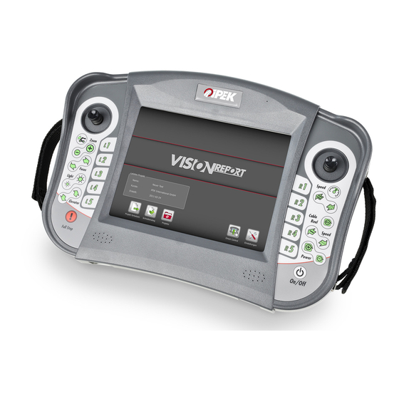
Control panel VISIONCONTROL - Version VC200 Functional description Control panel VISIONCONTROL - Version VC200 1 800x600 Touchscreen 2 Connection panel for 2 x USB 2.0, Ethernet and S-Video 3 Joystick (right) for crawler control 4 Button group for cruise control mode 5 Button for switching over between Automatic and Manual mode of the cable reel 6 Button group for cable reel speed control 7 Button group for cable reel power control... - Page 20 Functional description Control panel VISIONCONTROL - Version VC200 Connector overview: Express-Card (not supported) S-Video RJ 45 USB Device (not supported) NOTE! The joysticks only control camera and crawler if you are in the main inspection view, i.e. the camera picture is visible. In system dialogs the right joystick has a navigation function while the left joystick will be disabled..
-
Page 21: Overview Buttons And Main Control Functions
Control panel VISIONCONTROL - Version VC200 Functional description Overview buttons and main control functions Joystick left: camera head right: crawler Function buttons L1 to L5 and R1 to R5 The function of these buttons is displayed in the software itself and depends of the current active menu. -
Page 22: Extended Functions And Further Advice
Functional description Control panel VISIONCONTROL - Version VC200 Extended functions and further advice Joystick Click left: The camera automatically moves into its home position. Joystick movements are ignored after a joystick click for one second. Joystick Click right: The crawler and the cable reel are stopped. Cruise control will be deactivated if it was active. - Page 23 Control panel VISIONCONTROL - Version VC200 Functional description Cruise control: When cruise control is engaged, you can also change the crawler speed by moving the joystick. Cable reel speed: The speed of the cable reel can only be changed using these buttons in Manual mode. Cable reel power: This setting does not have any function during the winding process in Automatic mode.
-
Page 24: Function Diagram / Software Diagram
Functional description Function diagram / software diagram Function diagram / software diagram VISIONREPORT System - Start Basic Settings / Locale (only at 1 system start) Inspection System Settings Simple Project General Project Overlay Texts, Service Area, Video, Screenshots, Events, Video, Screenshot, Touch Calibration Free Text, Set Meter Counter Sections, Events,... -
Page 25: User Interface
VISIONREPORT, the Direct Control mode is at your disposal. Moreover, you can access system settings and change them. Last Project Name: Test Customer: iPEK International GmbH Created: 2011-02-24 Direct Control Settings Switch off... -
Page 26: Inspection Interface
Functional description User interface Inspection interface 40h 10min 40h 10min 0,00m / 743,33m 13:50 Uhr 13:50 Uhr 1 Video image 2 Status bar with monitoring displays 3 Status bar with function displays 4 Touch screen buttons (referenced with R1 – R5 buttons on the VISIONCONTROL control panel) 5 Touch screen function menu buttons 6 Touch screen buttons (referenced with L1 –... -
Page 27: Inspection Interface - Full-Screen Mode
User interface Functional description Inspection interface – Full-Screen Mode Press the R5 button or the associated touch screen button to change the screen to full-screen view. The touch screen buttons R1 – R5 remain displayed as do the touch screen function menu buttons in the touch screen area. All buttons L1 – L5 retain their function according to the assignments to the touch screen buttons on the left that are now hidden. -
Page 28: General Screen Dialogs
Functional description General screen dialogs General screen dialogs System Settings You can configure the VISIONREPORT software in the System Settings dialog. This is where you make all the settings for display of text overlays, system time, or network settings. File dialog In the File dialog you make all the file selections. -
Page 29: View Screenshots / View Videos
General screen dialogs Functional description View Screenshots / View Videos Screenshot Selection Video Selection In the Screenshot Selection and Video Selection system dialogs all recorded screenshot data and video data is listed. Here you can call, view, manage, or delete the data you desire. Please note that screenshots and videos are always assigned to projects and only the data of the currently selected project is displayed. -
Page 30: Screen Keyboard
Functional description General screen dialogs Screen keyboard All text entries on the VISIONCONTROL control panel must be entered via the integrated screen keyboard. Whenever a text input is required in an input field the screen keyboard opens automatically when activating the field. The screen keyboard offers input assistance which saves previously entered texts for repeated input. -
Page 31: Number Pad
General screen dialogs Functional description Number pad Every numeric input on the VISIONCONTROL control panel must be entered via the integrated screen keypad. Whenever a numeric input is required in an input field the screen keypad opens automatically when activating the field. Input assistance: Number pad OK button to confirm the selection... -
Page 32: General Operating Instructions
Functional description General screen dialogs General operating instructions Extended scrolling In addition to the scroll bars of list views you also have the option to scroll directly by using the list itself. When you move your finger over the touch screen, the contents of a list view will move synchronously. Doing a quick move over the touch screen with your finger will trigger kinetic scrolling which will cause the contents to move faster and gradually come to a standstill. -
Page 33: Status Displays
Status displays Functional description Status displays 40h 10min 0,00m / 743,33m 13:50 Uhr Remote control is active ! Press FULL-STOP to return to pendant mode. remaining video current time recording time meter counter / overall meter counter / AutoStop active remote control Fig. -
Page 34: Notes For The Status Displays
Functional description Status displays Notes for the Status displays Camera Position Indicator: The Camera Position Indicator visualizes the current pan and tilt position of the camera head, whereas the inner circle of the graphic indicates a tilt position of 90 degrees, the outer circle a tilt position of 180 degrees. The red gradient horizon shows the current pan position of the camera. According to the pan movement, it moves in a circular path around the center of the graphic. -
Page 35: Address Data Management
Address data management Functional description Address data management On your VISIONCONTROL control panel you can manage address data for customers, contractors, and operators and select the responsible contacts in the respective project data. You create, manage, and delete address datasets in the project data overview. •... -
Page 36: Error Messages Of The System
Functional description Error messages of the system Error messages of the system Communication error (error code 0x00000016) This error occurs when there is a communication problem between the control panel and the rest of the system. In that case, the system will stop automatically for safety reasons. -
Page 37: User Interface
Selection of the locale sets the presets for the system language, the keyboard layout, and the catalogs that belong to the respective country. The standard profile for international activities is the “International” locale. NOTE! An up-to-date list of the available damage catalogues is available from your iPEK service partner or on the iPEK website. -
Page 38: Switching The Control Panel Off
User interface Switching the control panel on or off Switching the control panel off It can take up to 20 seconds to switch the control panel off. At the end of the process the connected inspection system will switch off by itself. The camera i.e. -
Page 39: Start Screen
Start screen User interface Start screen Last Project Name: Test Customer: iPEK International GmbH Created: 2011-02-24 Direct Control Settings Switch off Continue Project Quick Access Projects Overview Last Project This is where information on your last processed project is displayed. -
Page 40: System Settings
User interface System Settings System Settings Help Select help for information on the function of your VISIONCONTROL control panel, and the function and setting possibilities of the VISIONREPORT software. -
Page 41: Overlay Texts
In the Overlay Texts area you can format and preset possible text overlays. The following text headers are available for selection: - System Texts - Inspection Texts - Section Start Texts - Miscellaneous - Headlines iPEK International GmbH Header 1 See, Gewerbepark 22, D-87477 Sulzberg Header 2 Tel. +498376921800, FAX: +4983769218021 Header 3... -
Page 42: Overlay Texts - System Texts
User interface System Settings Overlay Texts – System Texts iPEK International GmbH Header 1 See, Gewerbepark 22, D-87477 Sulzberg Header 2 Tel. +498376921800, FAX: +4983769218021 Header 3 Freetext The following values can be set in the System Text area: Freetexts... -
Page 43: Section Start Texts
System Settings User interface Section Start Texts iPEK Spezial TV GmbH Kopfzeile 1 Duerenbodenstr. 7, D-87568 Hirschegg Kopfzeile 2 Tel. +4355173125, FAX: +4355173126 Kopfzeile 3 Frei positionierbare Texte These texts are only available for standard projects. With these texts, you can specify for... -
Page 44: Overlay Texts - Event Text
User interface System Settings Overlay Texts – Event Text iPEK International GmbH Header 1 See, Gewerbepark 22, D-87477 Sulzberg Header 2 Tel. +498376921800, FAX: +4983769218021 Header 3 Freetext The position and the presentation of the damage texts can be set for the overlay of Freetexts inspection texts. -
Page 45: Miscellaneous
System Settings User interface Miscellaneous iPEK International GmbH Header 1 Overlay of freetexts is only available if you are working with a simple project or Direct See, Gewerbepark 22, D-87477 Sulzberg Header 2 Tel. +498376921800, FAX: +4983769218021 Header 3 Control. Use the selection boxes to specify the position on the monitor at which the... -
Page 46: Overlay Texts - Headlines
In the area Software Info & Update you will find all the information about currently installed updates on your control panel. The installed file name (package name) as well as the installed version will be displayed. This information is primarily required for service cases, so that iPEK technicians... - Page 47 • Press the button SOFTWARE UPDATE in order to start the update process. NOTE! Please have the data of this overview on hand if there is a service case for your control panel. This will help the iPEK service technicians to more quickly create a detailed fault analysis.
-
Page 48: Update Process
User interface System Settings Update process Start update of VISIONCONTROL Connect VISIONCONTROL via network switch with the Internet connect with connect with network cable network cable Network Network with switch internet access Connectors at the top Start in menu Settings -> Software-Info & Updates -> Software Update With an existing internet connection the update will run automatically During the update process its current state is displayed. -
Page 49: Time & Language
System Settings User interface Time & Language Set the locale, the system time, and the system date in the “Time & Language” settings menu. The locale is already preselected when the control panel is switched on for the first time. By selecting the locale the presets for the system language, the keyboard layout, and the catalog are determined. -
Page 50: Network
User interface System Settings Network In order to access your device via network, it has to register itself with the network first. It does this by obtaining an IP address from the network. To do this push the button GET IP ADDRESS. If an IP address has been obtained it will be displayed in the appropriate line. The MAC address is always shown above the IP address. -
Page 51: System Info & Maintenance
System Settings User interface System Info & Maintenance The System Info & Maintenance page provides you with important information about your system. Overall uptime: Indicates the sum of inspection time, beginning from the delivery of the system. Overall meter counter: Indicates the sum of inspection length. -
Page 52: Factory Settings
User interface System Settings Factory settings Use the Factory Reset button to reset the control panel to delivery status. • Select Factory Reset. • In the dialog window confirm this selection with OK. ATTENTION! If you reset the VISIONCONTROL control panel to the factory settings, all system settings that you have entered will be lost. This also includes your customer database. -
Page 53: Calibrating The Touch Screen
System Settings User interface Calibrating the touch screen NOTE! Activate the cross-hairs only after you have completely executed the necessary calibration movements. Otherwise it may be the case that your touchscreen cannot be correctly calibrated. • Select the function Touch Calibration. •... - Page 54 User interface System Settings Calibrating movement • Confirm your input with the OK button. FACILITATED WORKSTEP!! If the settings of the touchscreen are so imprecise that you can no longer activate entries via the touchscreen then it is possible to trigger the calibration by simultaneously pressing the VISIONCONTROL buttons L5 and R5 (for approximately 5 sec.).
-
Page 55: Exit The System Settings
System Settings User interface Exit the system settings Once you have configured your system, exit the system settings to resume your project. • After configuring the system settings, confirm by activating the exit button. -
Page 56: Quick Access / Create A Simple Project
Events can only be created if a catalog is assigned to the simple project. Overlays of sections or logs are not possible. Last Project Name: Test Customer: iPEK International GmbH Created: 2011-02-24 Direct Control Settings Switch off... -
Page 57: Managing Projects
Managing Projects User interface Managing Projects Projects Overview In the Projects Overview area a list of the projects on your VISIONCONTROL is displayed. Simple as well as general projects are listed here. You obtain information on the project name, total size of the project data, the last modification, and the creation of the project. In addition, you also see which customer and contractor are assigned to the project, and whether the project has an assigned catalog. -
Page 58: Creating A New Project
User interface Managing Projects Creating a new project In this dialog you create a project and enter a name, as well as the project configuration for the project. In addition you can also create, manage, and delete address data for customers, contractors, and operators. - Mark the check box to select whether you want to create a simple project. - Page 59 Managing Projects User interface • Confirm your selection with continue. • Select or create a section for your inspection project. NOTE! A detailed description of section settings is provided starting on Seite 63. • Confirm your selection with OK. NOTE! General projects created with a catalog by CDLab can be imported into WinCan V8.
-
Page 60: Rename Project (Menu Extended Commands)
User interface Managing Projects Rename Project (Menu Extended Commands) Use this function to rename the currently selected project. • Select Rename Project. • Enter a new name and confirm the entry with OK. Import Project (Menu Extended Commands) You can copy a project from a USB drive onto your device again by using this command. •... -
Page 61: Export Project
Managing Projects User interface Export Project The data that is saved in a project includes all configuration data, as well as recorded inspection texts, screenshots, and video recordings. You can export a complete project folder structure to the storage medium of your choice and thus ensure that inspection data does not get lost. •... -
Page 62: Load Project
User interface Managing Projects Load Project The data that is saved in a project includes all configuration data, as well as recorded inspection texts, screenshots, and video recordings. You can continue an existing project and enter additional data. • Highlight a project in the projects overview. •... -
Page 63: Sections
Sections User interface Sections The term section refers to the part of a sewer inspection between two manholes. During a project you can collect data for multiple sections that you can analyze individually later. In the Section Overview the existing sections of a project are listed; new sections can be added and existing sections can be deleted. -
Page 64: Editing Section Properties
User interface Sections Editing section properties If you have opened a project in the lower function button bar, select the section button. All sections belonging to this project are listed in the Segment Overview dialog. Select the section that you would like to edit and change the values. •... -
Page 65: Deleting A Section
Sections User interface Deleting a section In order to delete a section you first have to go to the Section overview dialog. Go to this dialog by selecting the section button in the lower function button bar. This button is only displayed if you have not selected a section. If you create a general project, the Section overview dialog will be displayed directly after confirming the project settings. -
Page 66: Events
User interface Events Events Use events to add detailed damage overlays in the video image during a sewer inspection. While executing an inspection you can add new events, edit events, or delete events. When analyzing your inspection data you can precisely identify the point at which later maintenance work must be undertaken based on the events. -
Page 67: Creating A New Event
Events User interface Creating a new event You can create a new event from the main inspection view once you have started the video recording. • Select New Event. You are now in the system dialog in which you can create a new event. NOTE! The possible values of the following selection menu rely on the preset catalog. -
Page 68: Quick Input
User interface Events All functions of the Tools menu are shown below. • Select Photo + OK, to complete the event and simultaneously take an inspection photo at this point. NOTE! If you select the option Photo + OK in the image view a new photo of the current section will be created and saved. The screen- shot does not include the current text of the event. -
Page 69: Tools
Events User interface Tools The Tools menu allows you to select various helpful additional functions of the VISIONREPORT operating software while you are compiling an inspection event. You have the option of editing the meter counter, performing various measurements or adapting the text visualization. You can therefore record helpful additional information for later analyses regarding every event. -
Page 70: Event Overview
User interface Events Event Overview In the Event Overview all events belonging to the current section are listed in the sequence in which they were created. Thus you can quickly get an overview of previously recorded events. In addition you can delete events, correct errors and add events after the inspection. •... -
Page 71: Data Transfer To Storage Medium
Data transfer to storage medium User interface Data transfer to storage medium On your VISIONCONTROL control panel you can export your inspection data, load updates from remote directories, or save video and image data on different drives. All of these processes are executed in the data transfer dialog window. The file can be selected in the upper area of the dialog selection. -
Page 72: File Transfer Via Ftp
User interface File transfer via FTP File transfer via FTP NOTE! In order to load data onto the control panel via the ftp protocol, an IP address must be assigned to the control panel in the system settings under network. •... -
Page 73: Button Combinations
Button combinations User interface Button combinations Touch screen calibration Simultaneously press the L5 + R5 buttons for approximately 5 seconds. - Page 74 User interface File transfer via FTP...
-
Page 75: Executing The Inspection
Main inspection view Executing the inspection Executing the inspection Main inspection view After you have configured the settings on your VISIONCONTROL control panel you can start with the inspection. You see the main inspection view, in which the touch screen buttons (L1 – L5 & R1 – R5) are located on the left side and on the right side of the touch screen. The functions are always referenced with the buttons L1 –... -
Page 76: Functions Of The Touch Screen Buttons
Executing the inspection Functions of the touch screen buttons Functions of the touch screen buttons The functions of the touch screen buttons can vary based on project type. The appearance of active and inactive status, as well as the system dialogs that are displayed, vary and are described below. -
Page 77: Dialog Buttons
Functions of the touch screen buttons Executing the inspection Dialog buttons Dialog buttons open a system dialog in which you can make settings or manage files such as video and image data. All functions in the submenus of the operating menus are dialog buttons. The dialog buttons include: - View Images - View Videos... -
Page 78: View Images
Executing the inspection View Images View Images The Image View system dialog provides an overview of all recorded inspection screenshots of the currently selected section. If a section is not selected, then all screenshots of the current project will be displayed. The screenshots can be selected, viewed, and copied directly. In this dialog it is only possible to delete individual screenshots for a simple project. -
Page 79: View Videos
View Videos Executing the inspection View Videos The Video View system dialog provides an overview of all recorded inspection videos of the currently selected section. If a section is not selected then all videos of the current project will be displayed. The videos are presented in a list with their file names and can be directly selected, viewed, and copied. -
Page 80: Device Control
Executing the inspection Device Control Device Control In the device control you can change the hardware settings or the connected devices directly. The available settings depend on the devices that are connected to your system. If your system does not feature a locator that can be switched on or off, the associated option in the dialog will be disabled. - Page 81 Device Control Executing the inspection Camera macro 1 Panning of pipe connections: 1. Panning to +90° 2. 360° rotation in negative direction 3. Panning to 0° Camera macro 2 Panning to +90° and rotation by -90° Camera macro 3 Panning to +90° and rotation by +90° Camera macro 4 Panning to +90°...
-
Page 82: Operation Mode
Executing the inspection Device Control Operation Mode The operation mode describes the behavior of the camera head relative to pan and tilt. Depending on the design, the camera heads have integral sensors which can automatically respond to location changes. Device Control Camera Movement &... -
Page 83: Operation Mode - Standard Mode
Device Control Executing the inspection Operation Mode – Standard Mode The camera head follows the standard control functions through the joystick. In this regard please read the operating manual of the connected device. Operation Mode – Position Mode In Position Mode the camera head moves synchronously with the joystick. •... -
Page 84: Operation Mode - Cleaning
Executing the inspection Device Control Operation Mode – Cleaning Device Control Camera Movement & Locator Camera Makros Camera Operationmode Standard Horizontal Position Cleaning Locator Camera & Laser Miscellaneous System-Status Help Exit By pressing the button “Cleaning” the camera is moved to the rear upper position to 135°. This way the rear area of the tilting unit is accessible for cleaning. -
Page 85: Set Locator Mode
Device Control Executing the inspection Set Locator Mode Depending on the design, the camera heads have a controllable location transmitter whose frequency can be set. You can choose between a location frequency of 512 Hz and 640 Hz or completely switch off the location transmitter. Alternatively, you can also set the location frequencies of the crawler here. -
Page 86: Set Shutter
Executing the inspection Device Control Set Shutter You can set the camera’s shutter here.. Device Control Camera Movement & Locator Camera & Laser Shutter Open Close Manual Auto Iris Open Close Manual Auto Camera Slow Digital Auto Shutter Zoom Fokus Laser 100% Miscellaneous... -
Page 87: Set Iris
Device Control Executing the inspection Set Iris You can set the camera’s iris here. Device Control Camera Movement & Locator Camera & Laser Shutter Open Close Manual Auto Iris Open Close Manual Auto Camera Slow Digital Auto Shutter Zoom Fokus Laser 100% Miscellaneous... -
Page 88: Set Camera Closure
Executing the inspection Device Control Set camera closure You can set the camera’s closure here. Device Control Camera Movement & Locator Camera & Laser Shutter Open Close Manual Auto Iris Open Close Manual Auto Camera Slow Digital Auto Shutter Zoom Fokus Laser 100%... -
Page 89: Set Laser
Device Control Executing the inspection Set Laser If the connected camera has an integrated laser, you can set the intensity here. Device Control Camera Movement & Locator Camera & Laser Shutter Open Close Manual Auto Iris Open Close Manual Auto Camera Slow Digital... -
Page 90: Crawler
Executing the inspection Device Control Crawler Basic options for the crawler can be set in this section. Device Control Camera Movement & Locator Camera & Laser Miscellaneous Crawler Secure Clutch Slow Mode Aux. Light Video Source Internal External Others Reel Camera Standard Auto... - Page 91 Device Control Executing the inspection Slow mode When the clutch is switched on, the 1st gear is activated. You can select between 2 gears provided that the crawler used has a manual gearbox. The gears are shifted electrically, which is also possible during operation.
-
Page 92: Automatic Camera Centering
Executing the inspection Device Control Automatic camera centering Device Control Camera Movement & Locator Camera & Laser Miscellaneous Crawler Secure Clutch Slow Mode Aux. Light Video Source Internal External Others Reel Camera Standard Auto Mode Center System-Status Help Exit By pressing the automatic camera centering button the camera head is centrally positioned within the pipe. NOTE! Should the pipe diameter change during inspection the camera centering function must be activated again. -
Page 93: Reel Invert Mode
Device Control Executing the inspection Reel invert mode The reel invert mode can be activated to drive backwards into a pipeline with the crawler. Device Control Camera Movement & Locator Camera & Laser Miscellaneous Crawler Secure Clutch Slow Mode Aux. Light Video Source Internal External... -
Page 94: Auxiliary Light
Executing the inspection Device Control Auxiliary Light Basic options for the connected auxiliary light can be set in this section. Device Control Camera Movement & Locator Camera & Laser Miscellaneous Crawler Secure Clutch Slow Mode Aux. Light Video Source Internal External Others Reel... -
Page 95: Video Source
Device Control Executing the inspection Video source The signal path of the video source can be set here. An external video source can be connected via the S-Video interface on the rear of the control panel. Device Control Camera Movement & Locator Camera &... -
Page 96: System-Status
Executing the inspection Device Control System-Status This dialog shows you the connected devices and related information. This information is primarily needed for service purposes. • Select SYSTEM STATUS to view various diagnosis data of each connected device. Especially note the column on the right side - it will show you the pressure status of each device such as camera, crawler, elevator and extra light. -
Page 97: Text Menu
Text Menu Executing the inspection Text Menu In the Text Menu you can edit the displays of all currently available inspection texts and delete them from the image view. The submenu of the Text Menu includes the following function buttons: - Configure Custom Texts - Configure System Texts - Clear Custom Texts... -
Page 98: Configure System Texts
Executing the inspection Text Menu iPEK International GmbH Header 1 See, Gewerbepark 22, D-87477 Sulzberg Header 2 Tel. +498376921800, FAX: +4983769218021 Header 3 Line Freetext Freetexts Column 1970-01-01 00:00:01 Data displays 1000 mbar 0.00 m 0 gC Data displays e-mail:ISG_info@idexcorp.com Internet:www.ipek.at Footer Fig. -
Page 99: Extras
Extras Executing the inspection Extras Extended supplemental functions can be set in the Tools menu. Examples are setting the meter counter or entering notes. The functions depend on the relevant connected system and are only active if the system supports these functions. The submenu of the Tools menu includes the following function buttons: - Set Meter Counter - Set total Meter Counter... -
Page 100: Autostop
Executing the inspection Extras AutoStop The AUTOSTOP function allows you to automatically stop the crawler at a certain position, e.g. before reaching the lower position, when moving back from the inspection position. This function assists the user in retrieving the crawler. An additional meter counter display is displayed in the status bar of the control panel (AS) allowing you to check the actual position of the crawler. -
Page 101: Antiroll
Extras Executing the inspection AntiRoll The ANTIROLL function is used to automatically monitor and correct the lateral tilt of the crawler when travelling along the pipe system. If the crawler exceeds a certain tilt limit value it will be stopped. If the crawler tilts above a further angle, however, a warning message will appear. If the ANTIROLL function is activated it will only be effective if the crawler is moved in Cruise Control mode. -
Page 102: Notes
Executing the inspection Extras Notes The Notes system dialog enables you to add text notes to your inspection data. A text of any desired length can be saved for each project. Use the screen keyboard to write directly in the Notes window and save your input with OK. -
Page 103: Start Recording
Start Recording Executing the inspection Start Recording The action button Start Recording starts the recording of video data. If you are working in a general project you must first create or select a section. If you are working in a simple project you can specify the file in which the video will be saved. If you do not specify a file name by yourself, a default name will be used. -
Page 104: New Sections And Events
Executing the inspection Start Recording New sections and events While the video recording is running you can add new sections and create new events. When creating events and sections the video recording is stopped for this time period. For information on creating, managing, and editing sections and events see chapter “Operating interface” starting on Seite 63. Pause Recording During a running recording press the Pause Recording button. -
Page 105: Take Screenshot
Take Screenshot Executing the inspection Take Screenshot The action button Take Screenshot creates an inspection screenshot of the current view. This function is also active during a running video recording. The recording will then be stopped for the time involved in taking the screenshot, and then it will automatically continue. If you have opened a general project, you can take a screenshot only when you have created at least one event in the current section. -
Page 106: New Event
Executing the inspection New Event New Event Use events to add detailed damage overlays and a damage survey in the video image during a sewer inspection. While executing an inspection you can add new events, edit events, or delete events. When analyzing your inspection data you can precisely identify the point at which later maintenance work must be undertaken based on the events. -
Page 107: Inspection Menu
Inspection Menu Executing the inspection Inspection Menu This is where you delete, edit or create new events. You can select and edit sections and events as well; for general projects you can close sections. The submenu of the inspection menu includes the following function buttons: - Close Section (only with a running recording) - Sections - Event Overview (only with a running recording) -
Page 108: Protocol Preview
Executing the inspection Inspection Menu Protocol Preview In the protocol preview dialog you can get an overview of the current selected section in the form of a section protocol as well as an inclination protocol. The final section protocol and inclination protocol in PDF format will be created by the VISIONREPORT-Viewer; this dialog only shows you a preview of these protocols. -
Page 109: Inclination Measurement
Inspection Menu Executing the inspection • Select ZOOM + or ZOOM to enlarge or shrink the preview graphic. NOTE! You can only open the system dialog Protocol Preview when you have selected a section. NOTE! While the inclination measurement is running, the inclination protocol does not necessarily display the current state of the measurement. - Page 110 Executing the inspection Inspection Menu • Select START MEASUREMENT in order to start an inclination measurement either in forward or in backward direction. When performing a measurement in forward direction, only increasing meter values will be taken into account, when performing a backward measurement only decreasing meter values will be recorded.
-
Page 111: Toggle Screen
Toggle Screen Executing the inspection Toggle Screen Press the R5 button or the associated touch screen button to change the screen to full-screen view. The touch screen buttons R1 – R5 remain displayed as do the touch screen function menu buttons in the touch screen area. All buttons L1 – L5 retain their function according to the as- signments to the touch screen buttons on the left that are now hidden. -
Page 112: After The Inspection
Executing the inspection After the inspection After the inspection Note that after an inspection you must also back up the inspection data to an external storage medium. Please read the comments on data protection and backup on Seite 15. Data import into WinCan When you have created a general project with a catalog by CDLab, you can import it into WinCan V8. -
Page 113: Connection Via Usb-To-Serial Adapter
Set the text generator to iPEK DE-03SW. After a successful synchronisation the LED blinks at the USB-to-serial adapter and indicates the data transfer between VISIONCONTROL and PC. NOTE! USB-to-serial adapters of other manufacturers may work but are not supported by iPEK. -
Page 114: Interpretation Of The Inclination Protocol
Executing the inspection Interpretation of the inclination protocol Interpretation of the inclination protocol Example of a inclination protocol. Pipe Inclination chart Altitude Inclination 0% Inclination [%]: Inclination readings of the crawler in percent. The curve shows irregularities within the pipe which are typically caused by joints packings or debris.. Inclination 0,00 %: Shows the zero line of the inclination. -
Page 115: Measuring Functions
Prerequisites for use of the measuring functions Measuring Functions Measuring Functions The extended measuring functions of the VISIONREPORT inspection software are described below. You can call up these functions in the dia- logue via the „Tools“ menu when creating an event. The extended measuring functions help you to log and also determine diagnoses concerning damage points in the pipe quickly and directly. -
Page 116: Overview Of The Measuring Functions
Measuring Functions Overview of the Measuring Functions Overview of the Measuring Functions You can perform the following measurements using the VISIONREPORT inspection software: Measure cracks You can measure cracks here using the camera’s integral laser. Measure water level You can measure the level of the water in the pipe here. Measure bend You can measure the radius, angle and rotation of a bend here. -
Page 117: Principle Of The Measuring Function
Principle of the measuring function Measuring Functions Principle of the measuring function You always have to follow the same principle when measuring the various sizes. First, you must set the virtual pipe projected by the measuring software with its reference lines to your real pipe congruently. This reference target is the basis so that the measuring lines of the measurements output the exact reference and hence the correct measuring result. -
Page 118: Real View Of The Virtual Settings Lines In The Video View
Measuring Functions Overview of the Measuring Functions Real view of the virtual settings lines in the video view Setting line 1 Virtual Pipe Setting line 2 Virtual Pipe PIPE BRANCH: REAL PIPE: Diameter: 100.00mm Diameter: 150.00mm Angle: 45.00° Length: 105.50mm Rotation: 7.00°... - Page 119 Overview of the Measuring Functions Measuring Functions Measuring line: Pipe Branch REAL PIPE: Diameter: 150.00mm Length: 105.50mm Rotation: 2.80° Measuring lines: Water Level WATER LEVEL: Start: 12.75mm End: 12.10mm Rotation: 0.00° REAL PIPE: Diameter: 150.00mm Length: 105.50mm Rotation: 2.80° Measuring lines: Pipe Wall Object PIPE WALL OBJECT: Grid Unit: 5.00mm...
-
Page 120: Basic Setting Functions
Measuring Functions Basic setting functions Basic setting functions Joysticks The setting and measuring lines can be calibrated with the joysticks. Doubling the setting speed If you press on a joystick, the speed of the setting movement will double in the relevant direction. Function noT available This symbol indicates that no function is available in this direction. -
Page 121: Buttons
Basic setting functions Measuring Functions Buttons Certain functions are identical in all measurements in order to make control clear and easy for your inspection. This includes the options of individu- ally setting the setting and measuring lines as well as fonts or adjusting the 3D grid unit and its lines. Buttons are activated by pressing them and deactivated by pressing them again. -
Page 122: Measured Values Display
Measuring Functions Basic setting functions Measured Values Display REAL PIPE: Diameter: 150.00mm Length: 105.50mm Rotation: 2.80° Real Pipe 3D Grid Measured values of the relevant measurement PIPE BEND: Radius: 51.00mm Angle: 45.00° Rotation: 90.00° There are two areas of the measuring display in the relevant video view. One display shows the values of the real pipe. The other display shows the measured values of the relevant measurement. -
Page 123: Settings
Basic setting functions Measuring Functions Settings The settings area provided in every measuring option lets you show and set a virtual 3D grid for visualization of the pipe course. You can also load an inspection image which you can also use to perform a subsequent measurement. The Settings function is called up by pressing the button and hidden again of you press the button again. -
Page 124: Set Color Scheme
Measuring Functions Basic setting functions Set color scheme The color settings provided in every measuring option let you set the colours of the relevant setting or measuring lines and the text. The Set Color Scheme function is called up by pressing the button and hidden again if you press the button a second time. Color selection Select the color of the relevant measuring or setting lines depending on your inspection environment. -
Page 125: Measured Value Description
Measured value description Measuring Functions Measured value description The following table contains a complete overview of the individual measured values and a description of the measurements on which these values are based. Real Pipe Diameter Diameter of the pipe to be inspected Length Distance setting line 1 / setting line 2 Rotation... - Page 126 Measuring Functions Measured value description Measure pipe wall object Grid Unit Grid spacing of the 3D wire grid Distance Axial distance setting line 1 / measuring line 1 Rotation Rotation angle of the 3D wire grid around the center axis of the real pipe Length Length of the 3D wire grid in the pipe axis direction Arc Length...
-
Page 127: Reference Real Pipe
Reference real pipe Measuring Functions Reference real pipe You must pre-calibrate the pipe to be measured or reference the measuring software to this pipe as a basis for the following measurements. This presetting is the basic condition for all further measurements. Ensure as exact an alignment as possible here, as all further measurements depend on this setting. -
Page 128: Measure Cracks
Measuring Functions Measure cracks Measure cracks If you have connected a camera with an integrated laser to your system, you can use it for crack measurement. • You can change the brightness of the laser using the buttons 100%, 75%, 50% and OFF. Two crosshairs are overlayed onto the camera picture. -
Page 129: Measure Water Level
Measure water level Measuring Functions Measure water level This function allows you to measure the water level in the pipe. REAL PIPE: Diameter: 150.00mm Length: 105.50mm Rotation: 2.80° Measuring line 2 Measuring line 1 WATER LEVEL: Start: 12.75mm REAL PIPE: Diameter: 150.00mm End:... -
Page 130: Measure Bend
Measuring Functions Measure bend Measure bend This function allows you to define and measure a bend of the pipe to be inspected. To be able to use this function, you must be able to see a visible edge/coupling in the bend over the course of pipe via the camera view. All settings influence the visible location and position of measuring line 1 in this view. -
Page 131: Measure Branch
Measure branch Measuring Functions Measure branch This function allows you to define and measure a branch of the pipe to be inspected. All settings influence the visual location and position of measuring line 1 in this view. REAL PIPE: Diameter: 150.00mm Length: 105.50mm... -
Page 132: Measure Object On Pipe Wall
Measuring Functions Measure object on pipe wall Measure object on pipe wall This function allows you to determine and measure objects located on the pipe wall. A virtual measuring grid is projected optically on the pipe wall for this. You can then determine the dimensions of objects on the pipe wall via the spacing of the measuring grid. The measuring grid must be positioned fully over the pipe wall object for the measurements. -
Page 133: Measure Object On The Cross-Section
Measure object on the cross-section Measuring Functions Measure object on the cross-section This function allows you to determine and measure objects located in the cross-section area of the pipe to be inspected. A virtual measuring grid is projected optically on the cross-section level for this. You can then determine the dimensions of objects via the spacing of the measuring grid. Examples of these measurements are tree root penetrations or coupling offsets. - Page 134 Measuring Functions Measure object on pipe wall...
-
Page 135: Updating The Software
To keep your VISIONCONTROL control panel up to date, we recommend that you stay informed of updates to the software. You can get information about software updates directly from your iPEK dealer. An overview of all registered dealers is provided on Seite 171. - Page 136 Updating the software How to perform an online update...
-
Page 137: Gnu General Public License
GNU General Public License GNU General Public License Version 2, June 1991 Copyright (C) 1989, 1991 Free Software Foundation, Inc., 51 Franklin Street, Fifth Floor, Boston, MA 02110-1301 USA. Everyone is permitted to copy and distribute verbatim copies of this license document, but changing it is not allowed. General Public License Textform The entire license can be viewed under the following links: http://www.gnu.org/licenses/gpl-2.0.html... - Page 138 GNU General Public License...
-
Page 139: Customer Service Addresses
Customer service addresses Customer service addresses iPEK iPEK International GmbH See, Gewerbepark 22 87477 SULZBERG GERMANY Phone: +49 8376 921800 Fax: +49 8376 9218021 E-Mail: isg_info@idexcorp.com Web: www.ipek.at Australia Austria Sewer Equipment Company SPR TEC Europe GmbH König & Landl... - Page 140 +372 65 57503 Fax: +358 929 067 252 Fax: +45 9837 4677 E-Mail: info@nongroto.ee E-Mail: ilpo.hietanen@kamtek.fi E-Mail: jl@jklteknik.dk France IPEK France 1-3, rue Sétubal 60000 BEAUVAIS FRANCE Phone: +33 623 597927 E-Mail: contact@ipek-tv-france.com Germany Ehle-HD Entwicklungs- und Ehle-HD Entwicklungs- und GeHa-Tech S.
- Page 141 Customer service addresses Germany Gullyver GmbH Go2 GmbH Fink Leitungsmesstechnik Ges. für mobile Inspektionssysteme Lise-Meitner-Straße 8 Forach 1 Richard-Dunkel-Straße 116 71364 WINNENDEN 84405 DORFEN 28199 BREMEN GERMANY GERMANY GERMANY Phone: +49 421 5367350 Phone: +49 7195 76023 Phone: +49 8085 1891144 Fax: +49 421 5367354 Fax:...
- Page 142 Customer service addresses Italy Japan Luxembourg VIVAX s.r.l. Kantool CO., LTD SewerVision BV Via Scaldasole, 43 Matsudo Technical Center, Spoorstraat 17 27024 CILAVEGNA 315-5, Minamihanashima-Mukaimachi 6241 CL BUNDE ITALY MATSUDO-CITY, 271-0065 CHIBA(PREF.) THE NETHERLANDS JAPAN Phone: +39 0381 668301 Phone: +81 033 2520265 Phone: +31 43 3640130 Fax: +39 0381 96552...
- Page 143 Customer service addresses Serbia Slovenia Singapur Korekt Company PAL Inzeniring d.o.o. SewerVision BV Ranka Tajsica 5 Mlekarska ulica 13 Spoorstraat 17 11000 BEOGRAD 4000 KRANJ 6241 CL BUNDE SERBIA SLOVENIA THE NETHERLANDS Phone: +381 113975117 Phone: +386 51 641670 Phone: +31 43 3640130 Fax: +381 112465681 Fax:...
- Page 144 Customer service addresses Ukraine Vertex Ukraine LLC Envirosight LLC P. Grigorenka 39 B, of.6 111 Canfield Avenue - UNIT B3 02140 KIEV USA-Randolph, NJ 07869 UKRAINE UNITED STATES Phone: +38 0445 858790 Phone: +1 973 2526700 Fax: +38 0445 85879-50 Fax: +1 973 2521176 E-Mail: info@vertex-ukraine.com...
-
Page 145: Limitation Of Liability
The liability that we assume based on the conditions cited above is limited exclusively to repair, replacement or refund. iPEK is not liable for consequential damage or collateral damage that can arise in conjunction with the sale or operation of the product. This also applies for consequential damage that can be classified as commercial loss, such as lost profit, downtimes, damage to reputation, damage to equipment and/or property. - Page 146 Limitation of liability...
-
Page 147: Device Take-Back At The End Of Service Life
Device take-back at the end of service life The device delivered to you by iPEK is subject to the regulations specified in the European Directive 2002/96/EC and the appropriate implemen- tations in the law of the EC member states (in Germany: ElektroG). This means that you have the possibility of giving the device back at the end of its service life for proper disposal and recycling. - Page 148 Device take-back at the end of service life...
-
Page 149: Guarantee Declaration
Moreover the guarantee does not cover parts that are subject to wear, such as front glass, shaft end seals, lights, cables, etc., as well as damage that does not impair the serviceability of the system. If you have a guarantee claim please contact iPEK, your dealer, or the service organization closest to you, and submit the original invoice. - Page 150 Guarantee declaration Scope of the guarantee...
-
Page 151: Imprint
Operating instructions, manuals and software are copyrighted. The document may not be copied, reproduced, translated or transcribed into any form of electronic medium or into machine-readable form either in whole or in parts without prior written approval by iPEK. iPEK International GmbH... - Page 152 Imprint...
Need help?
Do you have a question about the VISIONCONTROL VC200 and is the answer not in the manual?
Questions and answers