Table of Contents
Advertisement
Advertisement
Table of Contents

Related Manuals for Inspur TS860M5


Summary of Contents for Inspur TS860M5
- Page 1 Inspur Server User Manual TS860M5...
- Page 2 Inspur. The information in this manual is subject to change without notice. Inspur is the registered trademark of Inspur. All the other trademarks or registered trademarks mentioned in this manual are the property of their respective holders.
- Page 3 4.Please install the product-compatible operating system and use the driver provided by Inspur. If you use an incompatible operating system or non-Inspur driver, it may cause compatibility issues and affect the normal use of the product, Inspur will not assume any responsibility or liability.
-
Page 4: Table Of Contents
Contents 1 Safety Instructions ......................... 1 2 Product Specification ........................5 2.1 Introduction ..........................5 2.2 Features and Specifications ......................6 3 Component Identification ......................8 3.1 Front Panel Components ......................8 3.2 Rear Panel Components ......................9 3.3 Motherboard Components......................11 3.4 Motherboard Jumper Introduction .................... - Page 5 6.1 Introduction ..........................24 6.2 Processor Option ........................24 6.3 Memory Option .......................... 26 6.4 Hot-plug HDD Option ......................... 27 6.5 Hot-plug PCIE Card Option......................28 6.6 Non-hot Plug PCIE Card Option ....................30 6.7 Redundant Hot-plug Power Supply Option ................30 7 Cabling ............................
- Page 6 9.15 Command Line Function Introduction ..................107 9.16 Time Zone Table ........................113 10 Common Faults, Diagnosis and ....................116 10.1 Hardware Problems ........................116 10.2 Software Problems ........................120 11 Battery Replacement ........................122 12 Regulatory Compliance Notices....................123 12.1 Regulatory Compliance Identification Numbers ...............
-
Page 7: Safety Instructions
For your safety, please do not attempt to remove the cover of the system to remove or replace any component without assistance provided by Inspur. Only service technicians trained by Inspur are authorized to remove the cover of the host, and to remove and replace internal components. - Page 8 The following considerations may help avoid the occurrence of problems that could damage the components or cause data loss, etc. In the event of the following, please unplug the power line plug from the power socket and contact Inspur’s customer service department:...
- Page 9 Close the host cover, reconnect the system to the power socket, and then power on. In case of operation failure or other abnormal situations, please contact Inspur and get technical support.
- Page 10 Upon receiving the proper authorization from Inspur and dismounting the internal components, please pay attention to the following: Switch the system power supply off and disconnect the cables, including all connections of the system.
-
Page 11: Product Specification
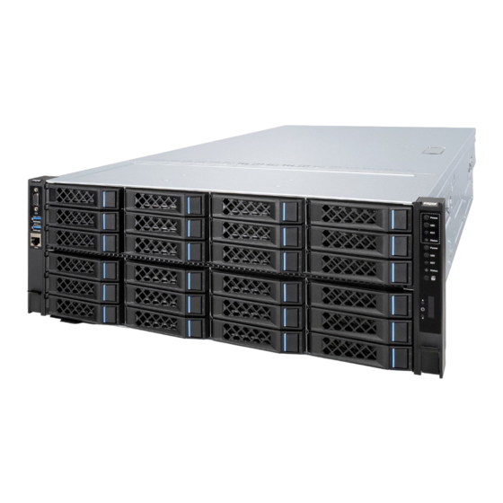
2 Product Specification 2.1 Introduction Inspur TS860M5 is a 4U, eight-socket rack server, which is designed on the basis of the new generation of Intel® Xeon® scalable processor. This product maintains the high quality and high reliability of Inspur servers. Compared with the previous 8-socket products, the performance has been greatly improved: ● H igh computing performance:... -
Page 12: Features And Specifications
support global clock redundancy and seamless switch of the system clock source. The power module supports Active-Active and Active-Standby redundancy modes, enabling millisecond-level switch. 2.2 Features and Specifications Processor Intel® Purley Skylake 81xx & 61xx series scalable processors Processor Type Intel®... - Page 13 Product Specification External Storage Drive Optical Drive Supports external USB drive Power Supports 800W/1300W/1600W and above output power; Specification Up to 4 power modules; Supports 2+1/2+2/3+1 redundancy depending on the configuration Power Input Please refer to the power input on the nameplate label of the host. Physical External Dimensions of 722 width ×...
-
Page 14: Component Identification
3 Component Identification 3.1 Front Panel Components Front View Item Description USB3.0 (x2) RJ45 connector HDD module 1 (supports NVME) Upper partition control buttons (only available in dual-partition mode) Power button UID LED & button Reset button System status LED KVM switch button LED module HDD module2... -
Page 15: Rear Panel Components
Component Identification Item Description Status & Interpretation Steady green: Normal Activity status LED Flashing green: Read and write activity Steady red: An HDD failure occurs Fault alarm LED Steady blue: HDD positioning Flashing blue: RAID rebuilding 3.2 Rear Panel Components Rear View –... - Page 16 Item Description UID LED & button IPMI 8-socket interconnection module OCP0 (supports PHY) OCP1 USB3.0 PCIE0_CPU4 - PCIE2_CPU4 PCIE3_CPU5 - PCIE5_CPU5 PCIE6_CPU1 - PCIE11_CPU1 PCIE0_CPU4 - PCIE1_CPU4 PCIE2_CPU5 - PCIE3_CPU5 PCIE4_CPU1 - PCIE7_CPU1 Rear View – Single Partition, Single Compute Node Rear View –...
-
Page 17: Motherboard Components
Component Identification 3.3 Motherboard Components CPU Board Item Description DIMMs_CPU1 CPU1 DIMMs_CPU0 CPU0 DIMMs_CPU2 CPU2 OCPA connector OCPC connector OCPB connector DIMMs_CPU3 CPU3 PCH connector M.2 riser card connector... - Page 18 Half-height IO Board Item Description PCIE0_CPU4 - PCIE2_CPU4 PCIE3_CPU5 - PCIE5_CPU5 PCIE6_CPU1 - PCIE11_CPU1 Intrusion switch connector HDD_BP1 management port (lower HDD BP) HDD_BP0 management port (upper HDD BP) KVM_UI connector HDD_BP1 power connector (lower HDD BP) HDD_BP0 power connector (upper HDD BP) Raid card slot0_CPU0 Raid card slot1_CPU4...
- Page 19 Component Identification Full-height IO Board Item Description CTL_UI connector OLED connector Raid card slot0_CPU0 Raid card slot1_CPU4 PCIE_Riser0 - GPU power connector0 PCIE_Riser0 - GPU power connector1 PCIE_Riser0_CPU4\CPU5 PCIE_Riser1_CPU1 PCIE_Riser1 - GPU power connector1 PCIE_Riser1 - GPU power connector0 HDD_BP0 power connector (upper HDD BP) Intrusion switch connector HDD_BP1 management port...
-
Page 20: Motherboard Jumper Introduction
3.4 Motherboard Jumper Introduction Item Description Function Short-circuit Pin2/4, restore to normal status; short-circuit Pin4/6, clear CLR_CMOS CMOS clear jumper CMOS. Note: The jumper pins are located on the PCH board. It is required to shut down the system, as well as disconnect the power supply during CMOS clearing. -
Page 21: Operations
Operations 4 Operations 4.1 Power up the Server Insert the power cord plug, then press the Power Button. 4.2 Power down the Server WARNING: To reduce the risk of personal injury, electric shock, or damage to the equipment, remove the power cord to remove power from the server. The front panel Power Button does not completely shut off system power. -
Page 22: Remove The Access Panel
4.4 Remove the Access Panel WARNING: To reduce the risk of personal injury from hot surfaces, allow the drives and the internal system components to cool before touching them. CAUTION: For proper cooling, do not operate the server without the access panel, air baffle, or fan installed. -
Page 23: Remove The Io Module
Operations 4. Open the handles, and remove the compute node. 4.6 Remove the IO Module WARNING: To reduce the risk of personal injury from hot surfaces, allow the drives and the internal system components to cool before touching them. Power down the server. Extend the server from the rack. -
Page 24: Install The Access Panel
Remove the IO module along the direction shown in the following figure. 4.7 Install the Access Panel Open the hood latch, and place the access panel onto the server. Press the hood latch down until the access panel slides to the closed position. Use the screwdriver to tighten the security screw on the hood latch. -
Page 25: Setup
Leave a minimum clearance of 121.9 cm (48 in) from the back of the rack to the back of another rack or row of racks. Inspur Servers draw in cool air through the front door and expel warm air through the rear door. Therefore, the front and rear rack doors must be adequately ventilated to allow ambient room air to enter the cabinet, and the rear door must be adequately ventilated to allow the warm air to escape from the cabinet. - Page 26 adequate airflow (equivalent to the required 64 percent open area for ventilation). • Side—The clearance between the installed rack component and the side panels of the rack must be a minimum of 7 cm (2.75 in). 5.1.2 Temperature Requirements To ensure continued safe and reliable equipment operation, install or position the system in a well-ventilated, climate-controlled environment.
-
Page 27: Rack Warnings
Because of the high ground-leakage currents associated with multiple servers connected to the same power source, Inspur recommends the use of a PDU that is either permanently wired to the building’s branch circuit or includes a nondetachable cord that is wired to an industrial-style plug. -
Page 28: Identifying The Contents Of The Server Shipping Carton
• The stabilizing feet are attached to the rack if it is a single-rack installation. • The racks are coupled together in multiple-rack installations. • Only one component is extended at a time. A rack may become unstable if more than one component is extended for any reason. -
Page 29: Installing The Operating System
Method to install an operating system on the server: Load the operating system into a USB device, boot the server through the USB device to install the OS. This process may require you to obtain additional drivers from the Inspur website(http://www.inspur.com). -
Page 30: Hardware Options Installation
6 Hardware Options Installation 6.1 Introduction If more than one option is being installed, read the installation instructions for all the hardware options and identify similar steps to streamline the installation process. WARNING: To reduce the risk of personal injury from hot surfaces, allow the drives and the internal system components to cool before touching them. - Page 31 Hardware Options Installation Step 2: Align the heatsink position marked by “1” with the Clip’s triangle mark, vertically align the mounting holes on the heatsink with those on the Clip, and assemble the heatsink and Clip together.
-
Page 32: Memory Option
Step 3: Install the assembled heatsink module onto the CPU socket, and the position marked by “1” should be aligned with the triangle mark on the CPU socket. Tighten the screws according to the sequence of 1, 2, 3, 4. Notes: ●... -
Page 33: Hot-Plug Hdd Option
Hardware Options Installation Remove the dummy memory module. Install the DIMM: Step 1: Open the lock tabs on both ends of the DIMM slot. Step 2: Align the bottom key with the receptive point on the slot, press both ends of the DIMM with your thumbs. -
Page 34: Hot-Plug Pcie Card Option
Step 4: Rotate the right side of the HDD upward 45 degrees, and then remove the HDD from the tray. Install a new HDD into the tray, and install it back into the server. 6.5 Hot-plug PCIE Card Option CAUTION: For proper cooling, do not operate the server without the access panel, baffles, expansion slot covers, or blanks installed. - Page 35 Hardware Options Installation Step 1: Press the corresponding PCIE button, the LED (green) flashes and then goes out. Step 2: Open the PCIE fixing plate as shown in the figure. Step 3: Remove the PCIE card. Step 4: Replace it with a new PCIE card, and install back to the server.
-
Page 36: Non-Hot Plug Pcie Card Option
6.6 Non-hot Plug PCIE Card Option CAUTION: To prevent damage to the server or expansion boards, power down the server and remove all AC power cords before removing or installing the PCIE Riser cage. CAUTION: For proper cooling, do not operate the server without the access panel, baffles, expansion slot covers, or blanks installed. - Page 37 Cabling WARNING: To reduce the risk of personal injury from hot surfaces, allow the power supply or power supply blank to cool before touching it. Install the power supply into the power supply bay. Connect the power cord to the power supply. Route the power cord through the power cord anchor or cable management arm.
-
Page 38: Cabling
7 Cabling 7.1 Signal Line 1.Red: NVME cable connects the NVME drive backplane and the mezzanine board. 2.Blue: SAS cable connects the HDD backplane and the SAS/RAID card. 3.Green: I2C cable connects the HDD backplane and the IO board. 4.Purple: VGA and UI/OLED signal lines connect the control boards within the left and right ears and the IO board. -
Page 39: Power Cord
Cabling 7.2 Power Cord 1.Red: Connect the lower HDD backplane and the motherboard. 2.Blue: Connect the upper HDD backplane and the motherboard. 3.Green: Connect the GPU on the Riser0 module and the motherboard. 4.Purple: Connect the GPU on the Riser1 module and the motherboard. - Page 40 CAUTION: Please route the cables according to the purchased machine configuration.
-
Page 41: Bios Setup
8.1 Login to BIOS Interface Power on the server. The system will then start to boot. When the following content appears below Inspur logo on the screen: “Press <ESC> to Front Page or <DEL> to Setup or <F11> to... - Page 42 Boot Menu or <F12> to PXE Boot.” Press DEL key. When “Entering Setup …” appears in the lower right corner of the screen, it will enter the BIOS setup soon. In the BIOS main menu, you could select the subitem through direction keys to enter the submenu. Other hotkeys function: •...
-
Page 43: Bios Parameter Description
8.2 BIOS Parameter Description 8.2.1 Front Page When Inspur Logo appears during system boot, press ESC to enter the BIOS Front Page interface, which includes product model, BIOS version, CPU information, memory information and boot device management options, as shown in the following figure:... - Page 44 8.2.2 Main When the logo appears, press DEL to enter the BIOS Setup Main interface, or select the Setup Utility option on the Front Page interface to enter the BIOS Setup Main interface. BIOS Main interface contains the basic information of BIOS system, the version information of BIOS, BMC and ME, CPU model information, total memory capacity information and system time.
- Page 45 BIOS Setup Processor Type Display CPU type information System Bus Speed Display the speed of system bus System Memory Speed Display the memory speed Last Level Cache Display the last cache size Total Memory Display total memory size Language Display current Setup interface language System Date Display and set system date, allow changes, take effect immediately System Time...
- Page 46 8.2.3.1 Peripheral Configuration Peripheral Configuration interface is used for system peripheral device settings, as shown in the follow figure and table. Peripheral Configuration Interface Instruction Table Interface Parameters Function Description Default Value PCIe SR-IOV PCIe device SR-IOV setting Enabled PCIe ARI ARI capability setting Disabled ARI Forward...
- Page 47 BIOS Setup Video Configuration Interface Instruction Table Interface Parameters Function Description Default Value Display Mode Set display mode configure type Plug In First 8.2.3.3 SIO AST2500 SIO AST2500 interface is used for serial port settings, as shown in the following figure and table.
- Page 48 SIO AST2500 Interface Instruction Table Default Value Interface Parameters Function Description Enable Serial Port A Enable/disable serial port A 8.2.3.4 Socket Configuration Socket Configuration interface is used for system processor and memory related settings, as shown in the following figure and table. Socket Configuration Interface Instruction Table Interface Parameters Function Description...
- Page 49 BIOS Setup Processor Configuration Interface Instruction Table Interface Parameters Function Description Default Value Per-Socket Configuration Per-Socket setting submenu Per-Socket Information Per-Socket information display submenu Hype-Threading [ALL] Logical processor thread setting Enabled Execute Disable Bit Virus protecting technology setting Enabled Enable Intel(R) TXT Intel trustable execution technology setting Disabled Intel hardware-assisted virtualization technology settings...
- Page 50 Common RefCode Configuration Interface Introduction Interface Parameters Function Description Default Value Chose socket to output serial message MRC serial message display setting Socket0 MMIO High Granularity Size MMIO high resources granularity size setting 256G Numa Numa switching setting Enabled 8.2.3.4.3 UPI Configuration UPI Configuration interface is used for UPI related settings, as shown in the following figure and table.
- Page 51 BIOS Setup UPI Configuration Interface Instruction Table Interface Parameters Function Description UPI General Configuration UPI general configuration submenu UPI Per Socket Configuration UPI per-socket configuration submenu UPI General Configuration ● It will display UPI general configuration menu by entering UPI General Configuration submenu.
- Page 52 UPI General Configuration Interface Instruction Table Interface Parameters Function Description Default Value UPI Status UPI status display submenu Link Frequency Select UPI link frequency setting Auto UPI link power saving mode settings, which Link L0p Enable is made when bandwidth is half of the peak Auto bandwidth.
- Page 53 BIOS Setup Memory Configuration Interface Instruction Table Interface Parameters Function Description Default Value Enforce POR Enforce POR settings Auto Memory Configuration Memory frequency select setting Auto Rank Margin Tool Rank margin tool setting Disabled Set the pattern length for the rank margin tool when RMT Pattern Length 32767 it’s enabled...
- Page 54 ● Memory RAS Configuration It will display the memory RAS configuration by entering the Memory RAS Configuration submenu. Memory RAS Configuration Interface Instruction Table...
- Page 55 BIOS Setup Interface Parameters Function Description Default Value Operation RAS mode Display current operation RAS mode Operation ext RAS mode Display current operation extra RAS mode Support RAS mode Display supported RAS mode Support ext RAS mode Display supported extra RAS mode Mirror Mode Mirror mode setting Disabled...
- Page 56 8.2.3.3.6 Advanced Power Management Configuration Advanced Power Management Configuration interface is used for CPU power management settings, as shown in the following figure and table. Advanced Power Management Configuration Interface Instruction Table Interface Parameters Function Description CPU P State Control CPU P state control configuration submenu Package C State Control Package C state setting submenu...
- Page 57 BIOS Setup CPU P State Control Interface Instruction Table Interface Parameters Function Description Default Value Uncore Fre Limit Uncore frequency limit setting SpeedStep (Pstates) CPU P state setting Enabled Turbo Mode Turbo mode setting Enabled Package C State Control ● It will display the package C state configuration menu by entering Package C State Control submenu.
- Page 58 Package C State Control Interface Instruction Table Default Value Interface Parameters Function Description C0/C1 State Package C State Package C state setting CPU-Advanced PM Tuning ● Select CPU Advanced PM Tuning menu, select Energy Perf BIAS, and enter power performance setting interface, as shown below:...
- Page 59 BIOS Setup Energy Perf BIAS Interface Instruction Table Interface Parameters Function Description Default Value Power Performance Tuning Power performance tuning setting OS Controls EPB ENERGY_PERF_BIAS_CFG mode Performance setting Balanced Performance 8.2.3.5 ME Configuration ME Configuration interface displays the information related with ME configuration. The general information of ME configuration will be displayed by entering Server ME Configuration submenu.
- Page 60 Sever ME Configuration Interface Instruction Table Interface Parameters Function Description ME-BIOS Interface Ver. ME BIOS interface version ME SKU ME SKU ME Firmware Type ME FW type Operational Firmware Version Current operational ME FW version Backup Firmware Version Backup ME FW version Recovery Firmware Version Recovery ME FW version...
- Page 61 BIOS Setup PCH Configuration Interface Instruction Table Interface Parameters Function Description PCH Devices Intel IO control hub device setting submenu PCH Express Configuration PCH Express devices display and setting submenu PCH SATA Configuration PCH SATA configuration submenu PCH sSATA Configuration PCH sSATA configuration submenu USB Configuration PCH USB configuration submenu...
- Page 62 PCH Devices Interface Instruction Table Default Value Interface Parameters Function Description PCH state after G3 Select S0/S5 for ACPI state after a G3 8.2.3.6.2 PCI Express Configuration PCH Express Configuration interface is used to set the options related with PCH PCIe, as shown in the following figure and table.
- Page 63 BIOS Setup PCI Express Configuration Menu Interface Instruction Table Default value Interface Parameters Function Description L1 Only PCI-E ASPM Support (Global) Setting ASPM support for all downstream devices PCIE Ports X Bifurcation Bifurcation of PCIe port X 8.2.3.6.3 PCH SATA Configuration/PCH sSATA Configuration PCH SATA Configuration/PCH sSATA Configuration interface is used to set the onboard PCH SATA/sSATA options, as shown in the following figures.
- Page 64 PCH SATA Configuration Menu Interface Instruction Table Interface Parameters Function Description Default value SATA Controller Enable or disable SATA controller Enabled Configure SATA as Set the SATA Controller as AHCI or RAID AHCI Port X Control Enable or disable SATA port X Enabled Port X Status SATA port X status...
- Page 65 BIOS Setup pressing F10 and system reboot. When the logo appears during system startup, press ESC to enter the Front Page interface, enter the Device Management configuration interface, and select Intel RSTe SATA/sSATA Controller to configure RAID. When the Boot Type is Legacy mode and the Load EFI Driver for RAID is set to Disabled, the system will load Legacy Option ROM to manage the SATA/sSATA RAID after pressing F10 and system reboot.
- Page 66 Key Instruction Table Description ↑↓ Used to move cursor in different menus or to change values of menu options. To select the next menu option. Enter To select a menu. To exit menu or return to previous menu from submenu. Menu Instruction Table Create RAID Volume To create an RAID volume.
- Page 67 BIOS Setup Create RAID Menu Instruction Table Interface Parameters Function Description Please enter a volume label name less than 16 characters without containing any Name special characters. Please select RAID volume level. If no volume has been created at present, there are four volume levels of RAID0 (Stripe), RAID1 (Mirror), RAID10 (RAID0+1) and RAID5 (Parity) for selection.
- Page 68 Mask Disk as Spare menu. After entering Mask Disk as Spare menu, system will display the HDDs not in RAID volume. Please use the space key to select the HDDs according to the actual demand, and then press Enter. The system will prompt “Are you sure you want to mask selected disks as Spare? (Y/N)”, enter “Y”...
- Page 69 BIOS Setup After entering sSATA RAID configuration interface, it will display the Create RAID Volume option, the existed RAID volumes (if present) information and non-RAID physical disks information.
- Page 70 Create RAID Volume. Enter this menu interface, as shown below. Create RAID Menu Instruction Table Interface Parameters Function Description Please enter a volume label name less than 16 characters without containing any Name special characters. Please select RAID volume level. If no volume has been created at present, there are four volume levels of RAID0 (Stripe), RAID1 (Mirror), RAID10 (RAID0+1) and RAID5 (Parity) for selection.
- Page 71 BIOS Setup Delete RAID Volume. Select a created RAID volume, and press Enter to view the RAID volume information. If you want to delete the RAID volume, select Delete, and press Enter to confirm it. 8.2.3.6.4 USB Configuration USB Configuration interface is used to set USB related options, as shown in the following...
- Page 72 figure and table. USB Configuration Interface Instruction Table Interface Parameters Function Description Default value USB0 (2.0 RearLeftUp) USB0 (2.0 RearLeftUp) setting Enabled USB1 (2.0 RearLeftDown) USB1 (2.0 RearLeftDown) setting Enabled USB2 (2.0 RearRightUp) USB2 (2.0 RearRightUp) setting Enabled USB3 (2.0 RearRightDown) USB3 (2.0 RearRightDown) setting Enabled USB4 (2.0 Internal)
- Page 73 BIOS Setup H2oUve Configuration Interface Instruction Table Interface Parameters Function Description Default Value Enabled H2OUVE Support Enable/disable H2OUVE support 8.2.3.6.6 IPMI Configuration IPMI Configuration interface is used to set IPMI related options, as shown in the following figure and table.
- Page 74 IPMI Configuration Interface Instruction Table Default Value Interface Parameters Function Description Enabled IPMI Support IPMI support switch setting System Interface Type System interface type of connecting BMC display BMC Status Current BMC status display BMC Firmware Version BMC firmware version IPMI Specification Version IPMI specification version A maximum waiting time period from POST to...
- Page 75 BIOS Setup Dedicated Ipv4 Source Ipv4 address source of dedicated port setting Dedicated Ipv4 IP Address Ipv4 IP address of dedicated port setting Dedicated Ipv4 Subnet Mask Ipv4 subnet mask of dedicated port setting Dedicated Ipv4 Gateway Address Ipv4 gateway address of dedicated port setting Enabled Sharelink Network Enable or disable sharelink network...
- Page 76 Security Interface Instruction Table Interface Parameters Function Description Current TPM Device Display current TPM device TPM State Display current TPM device status Supervisor Password Display supervisor password status User Password Display user password status Set a supervisor password. The password length should be 10-20 characters, Set Supervisor Password and it must include uppercase letters, lowercase letters, numbers and special characters at the same time.
- Page 77 BIOS Setup Power Interface Instruction Table Interface Parameters Function Description Default Value Auto wake on S5 setting. When set to Enabled, Auto Wake on S5 you can set to wake up the machine from S5 state Disabled automatically at a certain time. 8.2.6 Boot Boot interface is used to set system boot options, including boot type, boot priority, etc.
- Page 78 Boot Interface Instruction Table Interface Parameters Function Description Default Value Boot Type Select boot type UEFI Boot Type Network Stack Network stack support setting Enabled PXE Boot capability PXE boot setting UEFI:IPv4 EFI boot option setting submenu, the boot priority can be adjusted and set When Boot Type is set to Legacy Boot Type, save the setting and reboot the system.
- Page 79 BIOS Setup Legacy Boot Configuration Interface Instruction Table Interface Parameters Function Description Default Value Boot Type Select boot type Legacy Boot Type PXE Boot capability PXE boot setting Enabled Legacy boot option setting submenu, the boot priority can be Legacy adjusted and set 8.2.7 Exit Exit interface is used to set the options related with save and exit after changing BIOS...
-
Page 80: Firmware Update
8.3.1 Update BIOS in UEFI Shell When Inspur Logo appears during system startup, there is a prompt “Press <ESC> to Front Page or <DEL> to Setup or <F11> to Boot Menu or <F12> to PXE Boot.” on the bottom of the screen. - Page 81 BIOS Setup H20FFT-Sx64.efi XXXX.bin -ALL –SSB to flash BIOS+ME, and execute H20FFT-Sx64.efi XXXX. bin -ALL -BIOS –SSB to flash BIOS only, as shown in the following figure. Note: After updating ME+BIOS, please power off the machine, confirm that there is no residual electricity on the motherboard, and then power it on.
- Page 82 Notes: 1. For Linux system, it needs to run the H2OFFT tool as root. 2. After updating ME+BIOS, please power off the machine, confirm that there is no residual electricity on the motherboard, and then power it on.
-
Page 83: Bmc Settings
This section introduces the specifications that the management software follows and its main functions. The Inspur Server Management System is a control unit for server management, which is compatible with the management standard IPMI2.0 specification. Below are the main functions of the Inspur Server Management System: ●... -
Page 84: Functional Modules
This chapter introduces the Inspur Server Management System module composition, as well as the functions of these modules. 9.2.1 Module Composition The Inspur Server Management System is mainly composed of IPMI module, command line module, WEB module, KVM Over IP and virtual media. ●... -
Page 85: Web Interface Introduction
BMC Settings the internet. To use the remote control function, the client should be equipped with appropriate browser and Java runtime environment. 9.3 Web Interface Introduction This section introduces the Web interface of the management system, as well as operation steps to login the Web interface. - Page 86 9.3.2 Web Interface Introduction The Web interface helps users accomplish server management. The Web interface also has a help function so users can click the help button in the case that they may need The Web interface is divided into several parts, as shown in the following figure.
- Page 87 BMC Settings ● The name of the Web interface is displayed on top left of the interface. ● The meanings of all buttons on top right of the interface: Click on the Overview button, to return to the overview page. ◆...
- Page 88 Chinese and English). Click on the Help button to query help information on the corresponding page. ◆ Click on the Logout button, to return to the login page. ◆ ● The navigation tree is on the left. Via the nodes on the tree, you can select different functional interfaces.
- Page 89 BMC Settings 9.3.4 Information Select “Information” on the navigation tree. It contains the interfaces of system information, BIOS setup options, FRU information and history record, as shown in the following figures below. ● System information: Displays system configuration information, including CPU, memory, PCIE device, NIC, HDD, power supply unit, fan, temperature and voltage information.
-
Page 91: Storage
BMC Settings 9.4 Storage Select “Storage” on the navigation tree to open the storage interface. At present, the storage information control only supports LSI RAID card. This interface contains controller, physical drives, and logical drives information, as shown in the following figures. 9.5 Remote Control Select “Remote Control”... -
Page 92: Power And Fan
● Mouse mode settings: To set the mouse working mode for KVM remote console. 9.6 Power and Fan Select “Power Supply and Fan” on the navigation tree to open the power supply and fan interface. It contains the interfaces of power supply monitor, power supply configure, fan speed control, server power control and power peak settings, as shown in the following figures. - Page 93 BMC Settings output power, input voltage, output voltage, input current, output current and firmware version information. ● Power supply configure: Contains PSU present state, current state and A/S mode switch function. ● Server power control: Contains the server’s power on/off and reset, as well as the power policy on AC power loss.
-
Page 94: Bmc Settings
9.7 BMC Settings Select “BMC Settings” on the navigation tree to open the BMC Settings interface. It contains... - Page 95 BMC Settings the interfaces of BMC network, services, NTP, SMTP, alerts, access control, BMC share NIC switch and BIOS boot options, as shown in the following figures. ● BMC network management: Contains BMC network (static IP and DHCP), DNS settings and network interface bonding and network link information.
- Page 97 BMC Settings...
-
Page 98: Logs
9.8 Logs Select “Logs” on the navigation tree to open the related log interface. It contains the interfaces of system event log, BMC system audit log, black box log, event log setting and BMC system audit log setting, as shown in the following figures. ●... - Page 99 BMC Settings...
-
Page 100: Fault Diagnosis
9.9 Fault Diagnosis Select “Fault Diagnosis” on the navigation tree to open the fault diagnosis interface. It contains the interfaces of BMC self-inspection result, BMC recovery, capture screen and host POST code, as shown in the following figures. ● BMC self-inspection result: To view the BMC self-inspection result. ●... -
Page 101: Administration
BMC Settings 9.10 Administration Select “Administration” on the navigation tree to open the administration interface. It contains the interfaces of user administration, security, dual image configuration, dual firmware update, BIOS firmware update and restore factory defaults, as shown in the following figures. - Page 102 ● Restore factory defaults: To restore BMC’s configuration to factory state.
- Page 103 BMC Settings...
-
Page 105: Service & Protocol
BMC Settings 9.11 Service & Protocol BMC support network connection manager library to configure networking services configuration in run-time. RCMP+, HTTP/HTTPS, KVM, CD-MEDIA, FD-MEDIA, HD-MEDIA, SSH, TELNET and SOLSSH services are supported so far. User can enable or disable theses services, configure communication port, the session timeout value of the service and the maximum number of allowed sessions for the services. -
Page 106: Users
Note1: Http/Https(WEB) Timeout, if there is no web request in Timeout, web session will be deleted, and new web request will not respond, if web page has not auto update, web will logout when you change page or refresh page. Note2: Telnet is a non-security protocol, if not used, we suggest you disable it. -
Page 107: Bmc Firmware Update
BMC Settings Password - At password complexity check disabled, Password must be at least 1 character long. - At password complexity check enabled, Password must include special, uppercase, lowercase character and number, at least 8 characters long. - Not allow more than 16 characters. - Default disable complexity check, we strongly suggest you enable this function for security. - Page 108 one. 9.13.2 WEB Update BMC firmware update is supported via the Management Web GUI. BMC firmware update is configured with Watchdog. The watchdog time is 20 min. When entering the flash mode, the watchdog will be active, 20min timeout will reset the BMC automatically. When flashing the image, the watchdog will be active, 20 min timeout will reset the BMC automatically.
-
Page 109: Redfish
BMC Settings Execute the command socflash if=Imagefile to update image1; ● Execute the command socflash if=Imagefile offset=0x2000000 to update image2. ● 9.14 Redfish Redfish is a new management standard that uses the hypermedia RESTful interface to express data. It is oriented to the model, can express the relationship between modern system components and the semantics of services and components, easy to expand. - Page 110 9.14.3 DELETE Basic Format The client can delete the data under the specified URL via HTTP DELETE, so that the server can delete the specified configuration according to the URL. The basic format of DELETE access is as follows: curl -k -u username:password https://BMC_IP:8080/redfish/v1/SessionService/Sessions/1 -X DELETE Note: https://BMC_IP:8080/redfish/v1/SessionService/Sessions/1 is the address you want to...
- Page 111 BMC Settings “@odata.id”: “/redfish/v1/EventService” “Id”: “RootService”, “Links”: { “Sessions”: { “@odata.id”: “/redfish/v1/SessionService/Sessions” “Managers”: { “@odata.id”: “/redfish/v1/Managers” “Name”: “Root Service”, “Oem”: {}, “RedfishVersion”: “1.1.0”, “SessionService”: { “@odata.id”: “/redfish/v1/SessionService” “Systems”: { “@odata.id”: “/redfish/v1/Systems” “Tasks”: { “@odata.id”: “/redfish/v1/TaskService” “UUID”: “92384634-2938-2342-8820-489239905423” The URL of the device type to be accessed can be obtained based on the acquired resource above.
- Page 112 The URL to get the Chassis detailed information is /redfish/v1/Chassis/Chassis1: Request: curl -k -u username:password https://BMC_IP:8080/redfish/v1/Chassis/Chassis1 Response: “@odata.type”: “#Chassis.v1_2_0.Chassis”, “Id”: “1”, “Name”: “Computer System Chassis”, “ChassisType”: “RackMount”, “AssetTag”: “5180”, “Manufacturer”: “Inspur”, “Model”: “5180”, “SKU”: “8675309”, “SerialNumber”: “5180”, “PartNumber”: “224071-J23”, “PowerState”: “On”, “IndicatorLED”: “Lit”, “Status”: {...
-
Page 113: Command Line Function Introduction
BMC Settings “State”: “Enabled”, “Health”: “OK” “Thermal”: { “@odata.id”: “/redfish/v1/Chassis/1/Thermal” “Power”: { “@odata.id”: “/redfish/v1/Chassis/1/Power” “Links”: { “ComputerSystems”: [ “@odata.id”: “/redfish/v1/Systems/5180” “ManagedBy”: [ “@odata.id”: “/redfish/v1/Managers/BMC” “ManagersInChassis”: [ “@odata.id”: “/redfish/v1/Managers/BMC” “@odata.context”: “/redfish/v1/$metadata#Chassis.Chassis”, “@odata.id”: “/redfish/v1/Chassis/1”, “@Redfish.Copyright”: “Copyright 2014-2016 Distributed Management Task Force, Inc. (DMTF). For the full DMTF copyright policy, see http://www.dmtf.org/about/policies/ copyright.”... - Page 114 steps to the Web interface login. ● Login command line Introduces methods of login command line. ● Command line function introduction Introduces command line functions. 9.15.1 Command Line Login Login to BMC Command line through ssh. After logging in, enter the command line interface: Enter help to view online help: 9.15.2 Command Line Function Introduction 9.15.2.1 Get and Set Network Information...
- Page 115 BMC Settings 9.15.2.2 Get Sensor Information Via sensor command, get the information list of all sensors: 9.15.2.3 Get and Set FRU Information Via FRU command, get the FRU configuration information:...
- Page 116 9.15.2.4 Get and Control Chassis Status Via chassis command, get and control the system power status: 9.15.2.5 Get User List and Add/Delete User Via user command, get the user list, add or delete users: 9.15.2.6 Get BMC Version and Reset BMC Via mc command, get BMC version information and reset BMC:...
- Page 117 BMC Settings 9.15.2.7 Set Fan Mode and Get Fan Speed Via fan command, set the fan mode, and get the fan speed: 9.15.2.8 Get and Set Power Module Information Via psu command, get the power module information, and set power module as the main output: Get the power module information: 9.15.2.9 Change Root Password Via password command, change the root user’s password:...
- Page 118 9.15.2.10 Fault Diagnosis Via diagnose command, execute the tools and commands integrated in BMC to view the BMC status. 9.15.2.11 Collect Fault Logs Via dialog command, trigger the fault logs collection function. When the server fails, it can quickly collect the fault logs information stored in BMC. The collected fault logs can be downloaded through the browser or wget.
-
Page 119: Time Zone Table
BMC Settings 9.16 Time Zone Table Name of Time Zone Time Dateline Standard Time (GMT-12:00) International Date Line West Samoa Standard Time (GMT-11:00) Midway Island, Samoa Hawaiian Standard Time (GMT-10:00) Hawaii Alaskan Standard Time (GMT-09:00) Alaska Pacific Standard Time (GMT-08:00) Pacific Time (US and Canada); Tijuana Mountain Standard Time (GMT-07:00) Mountain Time (US and Canada) Mexico Standard Time 2... - Page 120 (GMT+01:00) Amsterdam, Berlin, Bern, Rome, Stockholm, W. Europe Standard Time Vienna W. Central Africa Standard Time (GMT+01:00) West Central Africa E. Europe Standard Time (GMT+02:00) Bucharest Egypt Standard Time (GMT+02:00) Cairo FLE Standard Time (GMT+02:00) Helsinki, Kiev, Riga, Sofia, Tallinn, Vilnius GTB Standard Time (GMT+02:00) Athens, Istanbul, Minsk Israel Standard Time...
- Page 121 BMC Settings Tokyo Standard Time (GMT+09:00) Osaka, Sapporo, Tokyo Yakutsk Standard Time (GMT+09:00) Yakutsk A.U.S. Central Standard Time (GMT+09:30) Darwin Cen. Australia Standard Time (GMT+09:30) Adelaide A.U.S. Eastern Standard Time (GMT+10:00) Canberra, Melbourne, Sydney E. Australia Standard Time (GMT+10:00) Brisbane Tasmania Standard Time (GMT+10:00) Hobart Vladivostok Standard Time...
-
Page 122: Common Faults, Diagnosis And
If there is a machine and a power module of the same type, you could change the power module to test whether there is a power module fault. If the instructions above do not resolve the problem, please contact Inspur customer service. - Page 123 KVM to check whether there is output on the monitor. If there is normal output, it indicates the VGA port may be abnormal, please contact Inspur customer service. If above operations could not resolve the problem, please contact Inspur customer service.
- Page 124 It needs to improve the server room’s environment, to avoid server over-temperature running because of too much dust. Check whether the server runs under high load. If above operations could not resolve the problem, please contact Inspur customer service.
- Page 125 When tested in a non-system situation, if the keyboard or mouse performance turns out to be normal, a system fault could be considered. If the keyboard or mouse fault still exists, a mainboard interface fault could be considered, and Inspur technical hotline can be called for support.
-
Page 126: Software Problems
Advanced System Property-> Advanced-> Performance-> Settings-> Change Virtual Memory, turn down the virtual memory or allocate the virtual memory to other partitions. If above operations could not resolve the problem, please contact Inspur customer service. 2) The memory capacity is abnormal Description: The memory capacity displayed in the OS and the physical memory capacity are inconsistent. - Page 127 4G memory at most. If the memory is not identified completely in BIOS Setup, confirm that the corresponding slots have been installed with memories of correct type. If above operations could not resolve the problem, please contact Inspur customer service. 3) Abnormal network Description: The network is disconnected, or the rate is lower than the actual rate of the network port.
-
Page 128: Battery Replacement
11 Battery Replacement If the server no longer automatically displays the correct date and time, you may need to replace the battery that provides power to the real-time clock. WARNING: The computer contains an internal lithium manganese dioxide, a vanadium pentoxide, or an alkaline battery pack. -
Page 129: Regulatory Compliance Notices
Regulatory Compliance Notices 12 Regulatory Compliance Notices 12.1 Regulatory Compliance Identification Numbers For the purpose of regulatory compliance certifications and identification, this product has been assigned a unique regulatory model number. The regulatory model number can be found on the product nameplate label, along with all required approval markings and information. -
Page 130: Cables
Compliance with these directives implies conformity to applicable harmonized European standards (European Norms) that are listed in the EU Declaration of Conformity issued by INSPUR for this product or product family and available (in English only) within the product documentation. -
Page 131: Korean Notice
Regulatory Compliance Notices that it is recycled in a manner that protects human health and the environment. For more information about where you can drop off your waste equipment for recycling, please contact your local city office, your household waste disposal service or the shop where you purchased the product. - Page 132 Batteries, battery packs, and accumulators should not be disposed of together with the general household waste. To forward them to recycling or proper disposal, use the public collection system or return them to Inspur, an authorized Inspur Partner, or their agents.
-
Page 133: Electrostatic Discharge
Use a portable field service kit with a folding static-dissipating work mat. If you do not have any of the suggested equipment for proper grounding, have an authorized reseller install the part. For more information on static electricity or assistance with product installation, contact Inspur Customer Service. -
Page 134: Warranty
Customers could return defective parts to the designated Inspur site after submitting a service request. Inspur may, at its discretion, repair or replace the defective parts. Repair or replacement parts may be new, used, or equivalent to new in performance and reliability. -
Page 135: Warranty Exclusions
14.3 Warranty Exclusions Inspur does not guarantee that there will be no interruptions or mistakes during the use of the products. Inspur will not undertake any responsibility for the losses arising from any operation not conducted according to Inspur Hardware Products.
Need help?
Do you have a question about the TS860M5 and is the answer not in the manual?
Questions and answers