Sign In
Upload
Manuals
Brands
Yamaha Manuals
Controller
RCX240
Yamaha RCX240 Manuals
Manuals and User Guides for Yamaha RCX240. We have
2
Yamaha RCX240 manuals available for free PDF download: User Manual, Supporting Supplement Manual
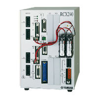
Yamaha RCX240 User Manual (620 pages)
4-AXIS ROBOT CONTROLLER
Brand:
Yamaha
| Category:
Controller
| Size: 8.28 MB
Table of Contents
Before Using the Robot Controller (be Sure to Read the Following Notes)
4
Table of Contents
9
Chapter 1 Using the Robot Safely
17
Safety Information
19
Particularly Important Cautions
20
System Design Safety Points
20
Installation Safety Points
21
Wiring Safety Points
22
Start-Up and Maintenance Safety Points
23
Safety Precautions During Robot Operation
25
Precautions for Disposal
25
Safety Measures for Robots
26
Safety Measures for SCARA Type Robots
26
Safety Measures for Single-Axis Robots, Cartesian Robots, and Pick & Place Robots
26
Motor Overload Precautions
26
Warning Labels and Marks
26
Warning Labels
26
Warning Marks
27
Industrial Robot Operating and Maintenance Personnel
27
Make Daily and Periodic Inspections
27
Freeing a Person Caught by the Robot
28
Warranty
30
Operating Environment
31
System Overview
35
Main System Configuration
35
Axis Definition for the RCX240
37
External View and Control System
38
RCX240 External View
38
Controller System
38
Optional Devices
39
RPB Programming Box
39
Expansion I/O Board
39
Regenerative Unit
39
Basic Sequence from Installation to Operation
40
When Using Absolute Type Axes Only
40
When Using Incremental Type Axes Only
41
When Using both Absolute and Incremental Type Axes
42
Chapter 3 Installation
43
Unpacking
45
Packing Box
45
Installing the Robot Controller
46
Installation Conditions
46
Installation Methods
47
Connector Names
50
Connecting to the Power
51
Power Supply Connection Example
51
Power Supply and Ground Terminals
52
AC Power Connector Wiring
53
Considering Power Capacity and Generated Heat Amount
54
Installing an External Leakage Breaker
56
Installing a Circuit Protector
56
Installing an Electromagnetic Contactor
57
Installing a Noise Filter
57
Installing a Surge Absorber
58
Connecting the Robot Cables
59
Connecting the RPB Programming Box
60
I/O Connections
61
Connecting a Host Computer
62
Connecting the Absolute Battery
63
Replacing the Absolute Battery
65
Connecting a Regenerative Unit
66
Precautions for Cable Routing and Installation
67
Wiring Methods
67
Precautions for Installation
69
Methods of Preventing Malfunctions
69
Checking the Robot Controller Operation
70
Cable Connection
70
Emergency Stop Input Signal Connection
71
Operation Check
72
Operation Overview
79
The RCX Robot Controller
80
Part Names
80
Main Functions
80
RPB Programming Box
81
Part Names
81
Main Functions
81
Connection to the Robot Controller
83
Changing the RPB Screen Settings
84
Turning Power on and off
85
Operation Keys
87
RPB Screen
87
Operation Key Layout
89
Basic Key Operation
90
Function Keys
91
Control Keys
93
Data Keys
95
Other Keys
95
Emergency Stop
96
Emergency Stop Reset
97
Mode Configuration
99
Basic Operation Modes
99
Other Operation Modes
100
Mode Hierarchy
101
Chapter 4 Operation
104
SERVICE" Mode
106
Operation Device
106
Prohibition of "AUTO" Mode Operation
106
Hold-To-Run Function
106
Limitations on Robot Operating Speed
107
AUTO" Mode
108
Automatic Operation
111
Stopping the Program
112
Resetting the Program
113
Switching Task Display
115
Switching the Program
116
Changing the Automatic Movement Speed
117
Executing the Point Trace
118
PTP Motion Mode
120
ARCH Motion Mode
123
Linear Interpolation Motion Mode
127
Direct Command Execution
130
Break Point
131
Setting Break Points
131
Deleting Break Points
132
Executing a Step
133
Skipping a Step
134
Executing the Next Step
134
PROGRAM" Mode
135
Scrolling a Program Listing
136
Program Editing
137
Cursor Movement
139
Insert/Overwrite Mode Switching
140
Inserting a Line
141
Deleting a Character
141
Deleting a Line
142
User Function Key Display
142
Quitting Program Editing
143
Copying or Cutting Lines
143
Backspace
145
Line Jump
145
Searching a Character String
146
Directory
148
Cursor Movement
150
Registering a New Program Name
150
Directory Information Display
151
Copying a Program
152
Erasing a Program
153
Renaming a Program
154
Changing the Program Attribute
154
Displaying Object Program Information
155
Creating a Sample Program Automatically
156
Compiling
158
Line Jump and Character String Search
159
Registering User Function Keys
159
Resetting an Error in the Selected Program
162
MANUAL" Mode
163
Manual Movement
166
Displaying and Editing Point Data
170
Point Data Input and Editing
172
Restoring Point Data
173
Point Data Input by Teaching
174
Point Data Input by Direct Teaching
179
Point Jump Display
179
Copying Point Data
180
Erasing Point Data
181
Point Data Trace
182
Point Comment Input and Editing
183
Point Data Input by Teaching
185
Point Comment Input and Editing
185
Jump to a Point Comment
186
Copying a Point Comment
187
Erasing Point Comments
188
Point Comment Search
189
Point Data Error Reset
190
Displaying, Editing and Setting Pallet Definitions
191
Editing Pallet Definitions
193
Point Setting in Pallet Definition
194
Editing the Point in Pallet Definition
195
Setting the Point in Pallet Definition by Teaching
196
Pallet Definition by Teaching
196
Copying a Pallet Definition
199
Deleting a Pallet Definition
200
Changing the Manual Movement Speed
201
Displaying, Editing and Setting Shift Coordinates
202
Editing Shift Coordinates
205
Restoring Shift Coordinates
206
Editing the Shift Coordinate Range
207
Restoring a Shift Coordinate Range
209
Shift Coordinate Setting Method 1
210
Shift Coordinate Setting Method 2
213
Displaying, Editing and Setting Hand Definitions
216
Editing Hand Definitions
223
Restoring Hand Definitions
224
Hand Definition Setting Method 1
225
Changing the Display Units
227
Return-To-Origin
228
Return-To-Origin Operation
228
Semi-Absolute
230
Return-To-Origin Procedure
232
Absolute Reset
234
Checking Absolute Reset
235
Absolute Reset on each Axis
237
Absolute Reset on All Axes
243
Setting the Standard Coordinates
249
Setting the Standard Coordinates by 4-Point Teaching
252
Setting the Standard Coordinate by 3-Point Teaching
254
Setting the Standard Coordinates by Simple Teaching
257
Executing the User Function Keys
259
SYSTEM" Mode
260
Parameters
263
Parameter Setting
263
Parameter List
265
Robot Parameters
268
Axis Parameters
273
Other Parameters
291
Parameters for Option Boards
312
Option DIO Setting
314
Serial I/O Setting
315
Setting the Network Parameters
318
Communication Parameters
320
OPTION Parameters
330
Setting the Area Check Output
331
Setting the "SERVICE" Mode
340
Saving the "SERVICE" Mode Parameters
345
Help Display in "SERVICE" Mode
346
SIO Settings
347
Double-Carrier Setting
351
Before Using a Double-Carrier
351
Setting the Double-Carrier Parameters
352
Individual Axis Return-To-Origin by General-Purpose DI/SI
355
Individual Axis Return-To-Origin Function
355
Setting the Individual Axis Return-To-Origin
357
Timing Chart of Individual Axis Return-To-Origin by General-Purpose DI/SI
363
Initialization
367
Initializing the Parameters
368
Initializing the Memory
369
Initializing the Communication Parameters
370
Clock Setting
371
System Generation
372
Self Diagnosis
373
Controller Check
374
Error History Display
375
Displaying the Absolute Battery Condition
376
Displaying the Total Operation Time
377
System Error Details Display
378
Backup Processes
379
Internal Flash ROM
380
Loading Files
381
Saving Files
383
Initializing the Files
384
MONITOR" Mode
385
UTILITY" Mode
388
Canceling Emergency Stop; Motor Power and Servo On/Off
390
Canceling Emergency Stop
390
Motor Power and Servo On/Off
390
Enabling/Disabling the Sequence Execution Flag
392
Changing the Arm Type
393
Resetting the Output Ports
394
Changing the Execution Level
395
Changing the Execution Level
396
Displaying the Help Message
397
Changing the Access Level (Operation Level)
398
Changing the Access Level
399
Displaying the Help Message
400
Chapter 5 Two-Robot Setting
401
Explanation of Two-Robot Setting
403
Two-Robot Setting
403
System Configuration Example
405
Operations and Data When Using the Two-Robot Setting
406
AUTO" Mode
406
Changing the Automatic Movement Speed
406
Executing the Point Trace
407
MANUAL" Mode
409
Current Position
409
Manual Movement
410
Point Data
414
Point Data Input by Teaching
415
Input by Point Data Direct Teaching
416
Pallet Definition
417
Setting the Point in Pallet Definition by Teaching
417
Pallet Definition by Teaching
418
Changing the Manual Movement Speed
420
Shift Coordinates
421
Shift Coordinate Setting Method 1
423
Shift Coordinate Setting Method 2
424
Hand Definition
426
Hand Definition Setting Method 1
426
Absolute Reset
428
Checking Absolute Reset Status
428
Absolute Reset on each Axis (Mark Method)
429
Absolute Reset on each Axis (Stroke End Method / Sensor Method)
431
Absolute Reset on All Axes
433
SYSTEM" Mode
436
SYSTEM" Mode Initial Screen Format
436
Robot Parameters Screen Format
437
Axis Parameters Screen Format
438
Setting the Area Check Output
439
Double-Carrier Collision Prevention
441
Error Message Displays
446
Programming
447
Robot Languages Used in the Two-Robot Setting
447
Chapter 6 Parallel I/O Interface
449
Standard I/O Interface Overview
451
Power Supply
451
Connector I/O Signals
452
Connector Pin Numbers
453
Typical Input Signal Connection
454
Typical Output Signal Connection
456
Dedicated Outputs
456
General-Purpose Outputs
458
Dedicated Input Signal Description
459
Dedicated Output Signal Description
462
Dedicated I/O Signal Timing Chart
464
Controller Power ON, Servo on and Emergency Stop
464
Return-To-Origin
465
Absolute Reset
466
Switching to AUTO Mode, Program Reset and Execution
467
Stopping Due to Program Interlocks
468
General-Purpose I/O Signals
469
General-Purpose Input Signals
469
General-Purpose Output Signals
469
General-Purpose Output Signal Reset (Off)
469
Option I/O Interface Overview
471
ID Settings
472
Connector I/O Signals
473
Connector Pin Numbers
474
Typical Input Signal Connection
475
Typical Output Signal Connection
475
General-Purpose I/O Signals
476
General-Purpose Input Signals
476
General-Purpose Output Signals
476
General-Purpose Output Signal Reset (Off)
477
Ratings
478
Caution Items
479
Chapter 7 Safety I/O Interface
481
SAFETY I/O Interface Overview
483
Power
483
Connector I/O Signals
484
Connector Terminal Numbers
485
Emergency Stop Input Signal Connections
486
Dedicated Input Signal Connections
490
Input Signal Description
491
Dedicated Output Signal Connections
492
Meaning of Output Signals
492
Chapter 8 Rs-232C Interface
493
Communication Overview
495
Communication Function Overview
496
Communication Specifications
497
Connector
497
Transmission Mode and Communication Parameters
499
Communication Flow Control
500
Flow Control During Transmit
500
Flow Control During Receive
500
Other Caution Items
501
Character Code Table
503
Connecting to a PC
504
Before Beginning Work
505
Chapter 9 Periodic Inspection
505
Before Beginning Work
507
Periodic Inspection
507
Daily Inspection
507
Three-Month Inspection
508
Replacing the Fan Filter
509
Maintenance Parts
510
Controller Basic Specifications
513
RCX240 Basic Specifications
513
Controller Basic Functions
515
Robot Controller External View
516
RCX240 External View
516
Top View
516
Side View
516
Front View
516
Bottom View
516
Rear View
516
RPB Basic Specifications and External View
519
Error Messages
523
Robot Controller Error Messages
523
0] Warnings and Messages
526
1] Warnings (Error History Entry
529
2] Robot Operating Area Errors
530
3] Program File Operating Errors
534
4] Data Entry and Edit Errors
537
5] Robot Language Syntax (Compiling) Errors
538
6] Robot Language Execution Errors
547
9] Memory Errors
553
System Setting or Hardware Errors
557
I/O and Option Board Errors
559
RPB Errors
564
RS-232C Communication Errors
565
Memory Card Errors
567
Motor Control Errors
570
YC-Link (SR1) Related Error
578
Ivy System Errors
585
Major Software Errors
590
Major Hardware Errors
592
Alarm Messages (Major Errors) that Occurred in Electrical Gripper
598
Error Messages that Occurred in Electrical Gripper
601
RPB Error Messages
603
Troubleshooting
605
When Trouble Occurs
605
Acquiring Error Information
606
Acquiring Information from the RPB
606
Acquiring Information from the RS-232C
606
Troubleshooting Checkpoints
607
Advertisement
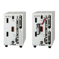
Yamaha RCX240 Supporting Supplement Manual (92 pages)
ROBOT CONTROLLER
Brand:
Yamaha
| Category:
Controller
| Size: 2 MB
Table of Contents
General Contents
5
Table of Contents
5
Chapter 1 Using the Robot Safely
9
Safety Information
11
Particularly Important Cautions
12
System Design Safety Points
12
Installation Safety Points
13
Wiring Safety Points
14
Start-Up and Maintenance Safety Points
15
Safety Precautions During Robot Operation
17
Motor Overload Precautions
18
Precautions for Disposal
18
Safety Measures for Robots
18
Safety Measures for SCARA Type Robots
18
Safety Measures for Single-Axis Robots, Cartesian Robots, and Pick & Place Robots
18
Warning Labels
19
Warning Labels and Marks
19
Warning Marks
19
Industrial Robot Operating and Maintenance Personnel
20
Make Daily and Periodic Inspections
20
Chapter 2 CE Marking
21
Cautions Regarding Compliance with EC Directives
23
CE Marking
23
Safety Standards
23
Applicable EC Directives and Their Related Standards
24
Cautions Regarding the Official Language of EU Countries
24
Robots Subject to CE Marking
24
Usage Conditions
25
Chapter 3 System Overview
27
Main System Configuration
29
System Overview
29
Basic Configuration
31
Control System Configuration
31
Power Supply and Emergency Stop System Circuit Configuration
34
Part Names and Functions
35
Programming Box (RPB-E)
35
RPB Connector
37
SERVICE Mode
39
What Is SERVICE Mode
39
Flow for Enabling the SERVICE Mode Functions
41
SERVICE Mode Parameter Settings
41
SERVICE Mode Level
42
Limitations on Operating Speed During SERVICE Mode
42
Operation Device Control During SERVICE Mode
42
Chapter 4 Emc Countermeasure
43
EMC Countermeasure Examples 4.1.1 RCX240
45
EMC Countermeasure Examples
45
Configuration
46
Rcx240
46
Countermeasure Components
47
Rcx221/Rcx222
52
Configuration
52
Countermeasure Components
53
Chapter 5 External Safety Circuit Examples
57
Performance Level
59
Circuit Examples for the RCX240
60
Category
62
Category
64
Overview of Circuit Operation
65
Circuit Examples for the RCX221/RCX222
66
Category
68
Category
69
Category
70
Overview of Circuit Operation
71
Chapter 6 Specifications
73
Basic Specifications
75
Rcx240
75
Rcx221
77
Rcx222
79
Controller
75
Basic Functions
81
External View
82
Rcx240
82
Rcx221
85
Rcx221Hp
86
Rcx222
87
Rcx222Hp
88
Basic Specifications
89
Rpb-E
89
Programming Box
89
External View
90
Rpb-E
90
Advertisement
Related Products
Yamaha RCX222
Yamaha RCX40
Yamaha RCX142
Yamaha RCX340
Yamaha CEmarking RCX221
Yamaha RCX141
Yamaha RCX1
Yamaha RCX series
Yamaha RC-D24
Yamaha RCR-1
Yamaha Categories
Motorcycle
Musical Instrument
Electronic Keyboard
Receiver
Amplifier
More Yamaha Manuals
Login
Sign In
OR
Sign in with Facebook
Sign in with Google
Upload manual
Upload from disk
Upload from URL