Sign In
Upload
Manuals
Brands
Kyocera Mita Manuals
All in One Printer
KM-3530
Kyocera Mita KM-3530 Manuals
Manuals and User Guides for Kyocera Mita KM-3530. We have
3
Kyocera Mita KM-3530 manuals available for free PDF download: Service Manual, Parts List
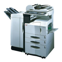
Kyocera Mita KM-3530 Service Manual (688 pages)
Brand:
Kyocera Mita
| Category:
All in One Printer
| Size: 8.03 MB
Table of Contents
Table of Contents
9
Service Manual
1
Safety Precautions
4
Installation Precautions
6
Precautions for Maintenance
7
Specifications
14
Copier
16
Parts Names and Their Functions
16
Operation Panel
17
Machine Cross Section
18
Drive System
19
Drive System 1 (Drive Motor and Eject Motor Drive Trains)
19
Drive System 2 (Paper Feed Motor Drive Train)
20
Drum
21
Installation Environment
21
Toner
21
Installation Procedure
22
Unpacking and Installation
22
Setting Initial Copy Modes
30
Copier Management
31
Using the Copier Management Mode
31
Copy Default
32
Setting Department Management Items
32
Machine Default
34
Language
35
Report
35
Installing the Key Counter (Option)
36
Installing the Drawer Heater (Option)
38
Installing the Paper Feed Desk (Option)
39
Installing the Large Paper Deck (Option)
42
Installing the Saddle Finisher/Switchback Unit (Option)
46
Installing the Sheet-Through Document Holder (Option)
55
1-2 Handling Precautions
21
1-3 Installation
22
Installing the Facsimile System (Option)
56
Installing the Printing System (Option)
66
Installing the Scanning System (Option)
68
Installing the Duplex Unit (Option)
71
Installing the Built-In Finisher (Option)
73
Installing the Job Separator (Option)
79
Installing the Network Facsimile System (Option)
82
Maintenance Mode
89
Executing a Maintenance Item
89
Maintenance Mode Item List
90
Contents of Maintenance Mode Items
93
Others
140
Mechanical Problems
213
Multiple Sheets of Paper Are Fed at One Time
213
No Primary Paper Feed
213
No Secondary Paper Feed
213
Paper Jams
213
Skewed Paper Feed
213
The Scanner Does Not Travel
213
Abnormal Noise Is Heard
214
Toner Drops on the Paper Conveying Path
214
Precautions
215
Precautions for Assembly and Disassembly
215
Running a Maintenance Item
216
Detaching and Refitting the Forwarding, Paper Feed and Separation Pulleys
217
Paper Feed Section
217
Detaching and Refitting the Bypass Separation, Bypass Papaer Feed and Bypass Forwarding Pulleys
219
Adjusting the Leading Edge Registration of Image Printing
224
Adjustment after Roller and Clutch Replacement
224
Adjusting the Leading Edge Registration for Memory Image Printing
225
Adjusting the Center Line of Image Printing
226
Adjusting the Margins for Printing
227
Adjusting the Amount of Slack in the Paper
228
Detaching and Refitting the Exposure Lamp
229
Optical Section
229
Detaching and Refitting the Scanner Wires
230
Detaching the Scanner Wires
230
Refitting the Scanner Wires
231
Detaching and Refitting the Laser Scanner Unit
234
Adjusting the Skew of the Laser Scanner Unit (Reference)
236
Detaching and Refitting the ISU (Reference)
237
Adjusting the Position of the ISU (Reference)
239
Adjusting the Longitudinal Squareness (Reference)
240
Adjusting Magnification of the Scanner in the Main Scanning Direction
241
Adjusting Magnification of the Scanner in the Auxiliary Scanning Direction
242
Adjusting the Scanner Leading Edge Registration
243
Adjusting the Scanner Center Line
244
Adjusting the Margins for Scanning an Original on the Contact Glass
245
Detaching and Refitting the Drum Unit
246
Detaching and Refitting the Main Charger Unit
246
Drum Section
246
Detaching and Refitting the Drum Separation Claw Assemblies
247
Detaching and Refitting the Developing Unit
248
Developing Section
248
Detaching and Refitting the Transfer Roller Assembly
249
Transfer Section
249
Detaching and Refitting the Fixing Unit
250
Detaching and Refitting the Heat Roller Separation Claws
250
Fixing Section
250
Detaching and Refitting the Press Roller
251
Detaching and Refitting the Fixing Heater M and S
252
Detaching and Refitting the Heat Roller
253
Detaching and Refitting the Fixing Unit Thermistor
254
Upgrading the Firmware on the Main PCB
255
Replacing the Backup ROM
256
Adjustment-Free Variable Resisters (VR)
257
Paper Feed Section
258
Main Charging Section
262
Optical Section
264
Original Scanning
265
Image Printing
266
Developing Section
269
Formation of Magnetic Brush
270
Computing the Absolute Humidity
271
Single Component Developing System
272
Transfer and Separation Sections
274
Cleaning and Charge Erasing Sections
276
Fixing Section
277
Eject and Switchback Sections
279
Electrical Parts Layout
281
Switches and Sensors
282
Other Electrical Components
285
Power Source PCB
286
Main PCB
289
Operation Unit PCB
298
Scanner Drive PCB
303
CCD Pcb
305
Maintenance Parts List
321
Periodic Maintenance Procedures
322
Optional Devices Supplied Parts List
324
Appendixes
328
Specifications
329
Part Names
330
Paper Misfeed Detection
334
Specifications
349
Machine Cross Section
351
Drive System
352
Unpacking
353
Paper Misfeed Detection
354
Paper Misfeed Indication
354
Paper Misfeed Detection Conditions
355
Paper Misfeeds
356
Electrical Problems
360
Mechanical Problems
362
Paper Jams
362
Abnormal Noise Is Heard
362
Precautions for Assembly and Disassembly
363
Construction of each Section
367
Stapler Section
371
Electrical Parts Layout
372
Periodic Maintenance Procedures
382
Assembly and Disassembly
401
Table of Contents
438
Part Names
439
Machine Cross Section
440
Drive System
441
Unpacking
442
Paper Misfeed Detection
443
Paper Misfeed Indication
443
Paper Misfeed Detection Conditions
444
Paper Misfeeds
445
Electrical Problems
446
The Switchback Conveying Motor Does Not Operate
446
The Switchback Eject Motor Does Not Operate
446
The Feedshift Solenoid Does Not Operate
446
The Press Solenoide Does Not Operate
446
Mechanical Problems
447
Paper Jams
447
Abnormal Noise Is Heard
447
Construction of each Section
448
Paper Switchback Operation
449
Electrical Parts Layout
450
Pcbs
450
Switches and Solenoids
451
Motors
452
Main PCB
453
Timing Chart No. 1
459
Paper Misfeed Detection Conditions
467
Paper Misfeeds
469
Self-Diagnosis
471
Self-Diagnostic Function
471
Self-Diagnostic Codes
472
Electrical Problems
474
Abnormal Noise Is Heard
476
Multiple Sheets of Paper Are Fed at One Time
476
Paper Jams
476
Precautions for Assembly and Disassembly
477
Precautions
477
Paper Feed Section
478
Wiring Diagram
499
Fax System (C)
501
Specifications
503
Table of Contents
588
Specifications
589
Main Body
592
Parts Names and Their Functions
592
Operation Panel
593
Basic Fax Screen on the Touch Panel
594
Mechanical Construction
596
Installation
597
Unpacking and Installation
597
Setting and Registering Data
605
Settings
605
Registration
606
1-2 Installation
605
Installing the Optional Memory Module DIMM
607
1-3 Maintenance Mode
609
Maintenance Mode
609
Maintenance Mode Item List
609
Contents of Maintenance Mode Items
612
Error Code
652
Error Codes
652
Error Code
653
Table of General Classification
653
U004XX Error Code Table: Interrupted Phase B
655
U006XX Error Code Table: Problems with the Unit
656
U008XX Error Code Table: Page Transmission Error
656
U009XX Error Code Table: Page Reception Error
656
U010XX Error Code Table: G3 Transmission
657
U011XX Error Code Table: G3 Reception
659
U017XX Error Code Table: V.34 Transmission
661
U018XX Error Code Table: V.34 Reception
661
U023XX Error Code Table: Relay Command Abnormal Reception
661
U044XX Error Code Table: Encrypted Transmission
661
Self Diagnosis
662
Self Diagnostic Codes
662
Troubleshooting
664
1-6 Requirements on PCB Replacement
670
Updating the Firmware
670
Updating the Firmware on the Fax Control PCB (FLASH ROM)
670
Updating the Firmware on the Fax Control PCB (Compact Flash Card)
673
2-1 Electrical Parts Layout
674
Electrical Parts Layout
674
2-2 Operation of the Pcbs
675
Fax Control PCB
675
Ncu Pcb
681
Auxiliary Power Source PCB
685
Advertisement
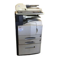
Kyocera Mita KM-3530 Service Manual (565 pages)
Brand:
Kyocera Mita
| Category:
Copier
| Size: 7.5 MB
Table of Contents
Table of Contents
8
Safety Precautions
3
Installation Precautions
5
Specifications
13
Parts Names and Their Functions
15
Copier
16
Operation Panel
16
Machine Cross Section
17
Drive System
18
Drive System 1 (Drive Motor and Eject Motor Drive Trains)
18
Drive System 2 (Paper Feed Motor Drive Train)
19
Drum
20
Installation Environment
20
Toner
20
Installation Procedure
21
Unpacking and Installation
21
Setting Initial Copy Modes
29
Copier Management
30
Using the Copier Management Mode
30
Copy Default
31
Setting Department Management Items
31
Machine Default
33
Language
34
Report
34
Installing the Key Counter (Option)
35
Installing the Drawer Heater (Option)
37
Installing the Paper Feed Desk (Option)
38
Installing the Large Paper Deck (Option)
41
Installing the Saddle Finisher/Switchback Unit (Option)
45
Installing the Sheet-Through Document Holder (Option)
54
1-2 Handling Precautions
20
1-3 Installation
21
Installing the Facsimile System (Option)
55
Installing the Printing System (Option)
63
Installing the Scanning System (Option)
65
Installing the Duplex Unit (Option)
68
Installing the Built-In Finisher (Option)
70
Installing the Job Separator (Option)
75
Maintenance Mode
77
Executing a Maintenance Item
77
Maintenance Mode Item List
78
Contents of Maintenance Mode Items
81
Transfer Section
237
Upgrading the Firmware on the Main Pcb
243
Replacing the Backup Rom
244
Main Charging Section
250
Developing Section
257
Transfer and Separation Sections
262
Cleaning and Charge Erasing Sections
264
Eject and Switchback Sections
267
Power Source Pcb
274
Main Pcb
277
Operation Unit Pcb
286
Scanner Drive Pcb
291
CCD Pcb
293
Maintenance Parts List
309
Periodic Maintenance Procedures
310
General Wiring Diagram
312
Troubleshooting
314
Specifications
315
Part Names
316
Machine Cross Section
317
Drive System
318
Unpacking
319
Paper Misfeed Detection
320
Paper Misfeed Indication
320
Paper Misfeed Detection Conditions
321
Paper Misfeeds
322
Electrical Problems
323
The Duplex Feed Clutch Does Not Operate
323
Mechanical Problems
324
Paper Jams
324
Abnormal Noise Is Heard
324
Precautions for Assembly and Disassembly
325
Precautions
325
Procedure for Assembly and Disassembly
326
Adjusting the Margin for Printing
326
Adjusting the Amount of Slack at the Registration Roller
327
Adjusting the Center Line of Image Printing
328
Construction of each Section
329
Paper Conveying Operation in Duplex Copying
330
Electrical Parts Layout
331
Periodic Maintenance Procedures
332
Table of Contents
334
Specifications
335
Part Names
336
Machine Cross Section
337
Drive System
338
Unpacking
339
Paper Misfeed Detection
340
Paper Misfeed Indication
340
Paper Misfeed Detection Condition
341
Paper Misfeeds
342
Self-Diagnosis
343
Self-Diagnostic Function
343
Self-Diagnostic Codes
343
Electrical Problems
346
The Feedshift Solenoid Does Not Operate
346
The Pickup Solenoid Does Not Operate
346
The Cooling Fan Motor Does Not Operate
347
Mechanical Problems
348
Paper Jams
348
Abnormal Noise Is Heard
348
Precautions for Assembly and Disassembly
349
Precautions
349
Adjusting the Positions of the Front Side Registration Cursor, Rear Side Registration Cursor and Trailing Edge Registration Cursor (Reference)
350
Cleaning the Stapler
351
Adjusting the Pressure of Curl Eliminator Mechanism
352
Construction of each Section
353
Paper Conveying Operation in Sort Mode
354
Intermediate Tray Section
355
Paper Registration on the Intermediate Tray
356
Stapler Section
357
Electrical Parts Layout
358
Paper Conveying Section
358
Intermediate Tray Section
359
Stapler Section
360
Main PCB
361
Periodic Maintenance Procedure
368
Table of Contents
371
Specifications
372
Part Names
373
Machine Cross Section
374
Drive System
375
Unpacking
376
Paper Misfeed Detection
377
Paper Misfeed Indication
377
Paper Misfeed Detection Condition
378
Paper Misfeeds
379
Electrical Problems
380
The Feedshift Solenoid Does Not Operate
380
Mechanical Problems
381
Paper Jams
381
Abnormal Noise Is Heard
381
Construction of each Section
382
Switching the Paper Path
383
Electrical Parts Layout
384
Periodic Maintenance Procedures
385
Assembly and Disassembly
387
Machine Cross Section
391
Drive System
392
Unpacking
393
Installing the Desk Dehumidifier (Service Part)
394
Paper Misfeed Detection
395
Paper Misfeed Indication
395
Paper Misfeed Detection Conditions
395
Paper Misfeeds
397
Self-Diagnosis
399
Self-Diagnostic Function
399
Self-Diagnostic Codes
399
Electrical Problems
401
The Desk Feed Clutch Does Not Operate
401
The Desk Upper Lift Motor Does Not Operate
402
The Desk Lower Lift Motor Does Not Operate
402
Others
403
Mechanical Problems
404
No Paper Feed
404
Skewed Paper Feed
404
Multiple Sheets of Paper Are Fed at One Time
404
Paper Jams
404
Abnormal Noise Is Heard
404
Precautions for Assembly and Disassembly
405
Precautions
405
Paper Feed Section
406
Detaching and Refitting the Forwarding, Paper Feed and Separation Pulleys
406
Replacing the Desk Upper or Lower Paper Width Switches
408
Replacing the Desk Feed, Upper and Lower Paper Feed Clutches
409
Adjusting the Position of the Rack Adjuster
411
Adjusting the Amount of Slack
412
Mechanical Construction
413
Electrical Parts Layout
416
Desk Main PCB
417
Appendixes
424
Part Names
425
Machine Cross Section
426
Drive System
427
Unpacking
428
Paper Misfeed Detection
429
Paper Misfeed Indication
429
Paper Misfeed Detection Conditions
430
Paper Misfeeds
431
Electrical Problems
432
The Switchback Conveying Motor Does Not Operate
432
The Switchback Eject Motor Does Not Operate
432
The Feedshift Solenoid Does Not Operate
432
The Press Solenoide Does Not Operate
432
Mechanical Problems
433
Paper Jams
433
Abnormal Noise Is Heard
433
Construction of each Section
434
Paper Switchback Operation
435
Electrical Parts Layout
436
Pcbs
436
Switches and Solenoids
437
Motors
438
Main PCB
439
Mechanical Construction
444
Appendixes
445
Timing Chart No. 1
445
Wiring Diagram
445
Parts Names
447
Machine Cross Section
448
Drive System
449
Unpacking
450
Installing the Dehumidifier Heaters (Service Part)
451
Paper Misfeed Detection
453
Paper Misfeed Detection Conditions
453
Paper Misfeed Indication
453
Paper Misfeeds
455
Self-Diagnosis
457
Self-Diagnostic Function
457
Self-Diagnostic Codes
458
Electrical Problems
460
The Deck Paper Conveying Motor Does Not Operate
460
The Large Paper Deck Does Not Operate When the Copier Main Switch Is Turned on
460
The Paper Conveying Clutch Does Not Operate
461
Mechanical Problems
462
Abnormal Noise Is Heard
462
Multiple Sheets of Paper Are Fed at One Time
462
No Primary Paper Feed
462
Paper Is Fed Askew
462
Paper Jams
462
Precautions for Assembly and Disassembly
463
Precautions
463
Paper Feed Section
464
Detaching and Refitting the Upper and Lower Deck Separation Rollers
464
Detaching and Refitting Deck Paper Feed Rollers 1 and 2
465
Detaching and Refitting the Deck Paper Conveying Unit Assembly
465
Adjusting the Position of the Center Adjuster (Center Line Alignment)
466
Adjusting the Amount of Slack
467
Mechanical Construction
468
Electrical Parts Layout
475
Deck Main PCB
478
Fax System (C)
487
Specifications
489
Parts Names and Their Functions
492
Copier
492
Operation Panel
492
Basic Fax Screen on the Touch Panel
494
Mechanical Construction
495
Setting and Registering Data
497
Settings
497
Registration
498
Installing the Optional Add-On Memory
499
Maintenance Mode
501
Maintenance Mode Item List
501
Contents of Maintenance Mode Items
504
Error Code
540
Error Codes
540
Error Code
541
Table of General Classification
541
U004XX Error Code Table: Interrupted Phase B
543
U006XX Error Code Table: Problems with the Unit
543
U008XX Error Code Table: Page Transmission Error
544
U009XX Error Code Table: Page Reception Error
544
U010XX Errror Code Table: G3 Transmission
545
U011XX Error Code Table: G3 Reception
547
U017XX Error Code Table: V.34 Transmission
549
U018XX Error Code Table: V.34 Reception
549
U044XX Error Code Table: Encrypted Transmission
549
Self Diagnosis
550
Self Diagnostic Codes
550
Updating the Firmware
551
Updating the Firmware on the Fax Control PCB (FLASH ROM)
551
Updating the Firmware on the Fax Control PCB (Compact Flash Card)
552
Electrical Parts Layout
554
Fax Control PCB
555
Ncu Pcb
559
Auxiliary Power Source PCB
563
Kyocera Mita KM-3530 Parts List (172 pages)
Kyocera Mita MFP Parts list
Brand:
Kyocera Mita
| Category:
All in One Printer
| Size: 25.41 MB
Table of Contents
Parts List
1
Exterior Covers
5
Paper Feed-In Section
11
Paper Conveying Section
17
Paper Exit Section
19
Bypass Unit
23
Fixing Section
31
Operation Unit
43
Key Counter
47
Cassette Heater
47
Wire Operation
52
Fig. 1 Exterior Covers
66
Index
75
FAX System(C)
158
Advertisement
Advertisement
Related Products
Kyocera Mita KM-3050
Kyocera Mita KM-4050
Kyocera Mita KM-5050
Kyocera Mita KM-8530
Kyocera Mita KM-1500
Kyocera Mita KM-2530
Kyocera Mita KM-4030
Kyocera Mita KM-4230
Kyocera Mita KM-5230
Kyocera Mita KM-7530
Kyocera Mita Categories
Printer
All in One Printer
Copier
Fax Machine
Printer Accessories
More Kyocera Mita Manuals
Login
Sign In
OR
Sign in with Facebook
Sign in with Google
Upload manual
Upload from disk
Upload from URL