
Related Manuals for Kyocera Mita KM-3530


Summary of Contents for Kyocera Mita KM-3530
- Page 1 KM-2530/3530 Contains: AD-63 F-2305 J-1402 MD-15 RA-1 ST-14 Fax System (C) SERVICE MANUAL Published in December ’01 2BH70763 Revision 3...
- Page 2 CAUTION DANGER OF EXPLOSION IF BATTERY IS INCORRECTLY REPLACED. REPLACE ONLY WITH THE SAME OR EQUIVALENT TYPE RECOMMENDED BY THE MANUFACTURER. DISPOSE OF USED BATTERIES ACCORDING TO THE MANUFACTURER’S INSTRUCTIONS. ATTENTION IL Y A DANGER D’EXPLOSION S’IL Y A REMPLACEMENT INCORRECT DE LA BATTERIE. REMPLACER UNIQUEMENT AVEC UNE BATTERIE DU MÊME TYPE OU D’UN TYPE REC- OMMANDÉ...
-
Page 3: Safety Precautions
Safety precautions This booklet provides safety warnings and precautions for our service personnel to ensure the safety of their customers, their machines as well as themselves during maintenance activities. Service personnel are advised to read this booklet carefully to familiarize themselves with the warnings and precautions described here before engaging in maintenance activities. - Page 4 Safety warnings and precautions Various symbols are used to protect our service personnel and customers from physical danger and to prevent damage to their property. These symbols are described below: DANGER: High risk of serious bodily injury or death may result from insufficient attention to or incorrect compliance with warning messages using this symbol.
-
Page 5: Installation Precautions
1. Installation Precautions WARNING • Do not use a power supply with a voltage other than that specified. Avoid multiple connections to one outlet: they may cause fire or electric shock. When using an extension cable, always check that it is adequate for the rated current..................... •... - Page 6 2. Precautions for Maintenance WARNING • Always remove the power plug from the wall outlet before starting machine disassembly....• Always follow the procedures for maintenance described in the service manual and other related brochures............................• Under no circumstances attempt to bypass or disable safety features including safety mechanisms and protective circuits.
- Page 7 • Do not pull on the AC power cord or connector wires on high-voltage components when removing them; always hold the plug itself....................... • Do not route the power cable where it may be stood on or trapped. If necessary, protect it with a cable cover or other appropriate item.
-
Page 8: Table Of Contents
2BH/J-3 CONTENTS 1-1 Specifications 1-1-1 Specifications ............................1-1-1 1-1-2 Parts names and their functions ......................1-1-3 (1) Copier ............................. 1-1-3 (2) Operation panel ..........................1-1-4 1-1-3 Machine cross section .......................... 1-1-5 1-1-4 Drive system ............................1-1-6 (1) Drive system 1 (drive motor and eject motor drive trains) .............. 1-1-6 (2) Drive system 2 (paper feed motor drive train) ................ - Page 9 2BH/J 1-5-3 Image formation problems ......................... 1-5-42 (1) No image appears (entirely white)....................1-5-43 (2) No image appears (entirely black)....................1-5-44 (3) Image is too light.......................... 1-5-45 (4) Background is visible........................1-5-45 (5) A white line appears longitudinally....................1-5-45 (6) A black line appears longitudinally.
- Page 10 2BH/J (38) The message requesting paper to be loaded is shown when paper is present in the upper drawer.................. 1-5-56 (39) The message requesting paper to be loaded is shown when paper is present in the lower drawer................... 1-5-56 (40) The message requesting paper to be loaded is shown when paper is present on the bypass tray.
- Page 11 2BH/J-3 1-6-5 Developing section ..........................1-6-34 (1) Detaching and refitting the developing unit .................. 1-6-34 1-6-6 Transfer section ..........................1-6-35 (1) Detaching and refitting the transfer roller assembly ..............1-6-35 1-6-7 Fixing section ............................. 1-6-36 (1) Detaching and refitting the fixing unit ................... 1-6-36 (2) Detaching and refitting the heat roller separation claws ...............
- Page 12 2BH/J Maintenance parts list ..........................2-4-15 Periodic maintenance procedures ........................ 2-4-16 General wiring diagram ..........................2-4-18 1-1-5...
-
Page 13: Specifications
2BH/J-3 1-1-1 Specifications Type ..........Desktop Copying system ......Indirect electrostatic system Originals ......... Sheets and books Maximum size: A3/11" × 17" Original feed system ...... Fixed Copy paper ........Drawer: Plain paper (60 – 105 g/m Bypass table: Plain paper (45 – 200 g/m Special paper: Transparencies, tracing paper, colored paper, letterhead and envelopes (when using the printer function only) Note: Use the bypass table for special paper. - Page 14 2BH/J Bit map memory ......9 MB (standard) Image storage memory ....23 MB (standard) Resolution ........600 × 600 dpi Light source ........Inert gas lamp Dimensions ........585 (W) × 646 (D) × 745 (H) mm 23" (W) × 25 "...
-
Page 15: Parts Names And Their Functions
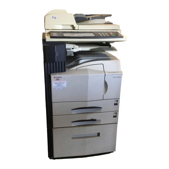
2BH/J 1-1-2 Parts names and their functions (1) Copier Figure 1-1-1 @ Main switch 1 Original cover # Copy store section 2 Operation panel $ Platen 3 Conveying cover handle % Original size scales 4 Conveying cover ^ Upper drawer 5 Bypass tray &... -
Page 16: Copier
2BH/J (2) Operation panel Printer Facsimile Auto Selection Management Interrupt Energy Saver Priority Output Priority Output Reset Copier Stop Printer Clear Scanner Start & 1 2 3 Figure 1-1-2 1 Start key (Indicator) 0 Auto selection key (Indicator) 2 Stop/clear key ! Facsimile priority output key (Indicator) 3 Reset key @ Printer priority output key (Indicator) -
Page 17: Machine Cross Section
2BH/J 1-1-3 Machine cross section Light path Paper path Figure 1-1-4 Machine cross section 1 Paper feed section 2 Main charging section 3 Optical section 4 Developing section 5 Transfer and separation section 6 Cleaning and charge erasing section section 7 Fixing section 8 Eject and switchback section 1-1-5... -
Page 18: Drive System
2BH/J 1-1-4 Drive system (1) Drive system 1 (drive motor and eject motor drive trains) As viewed from machine rear Figure 1-1-4 1 Drive motor gear 9 Registration clutch gear 2 Drum gear Z76H/Z30H 0 Gear Z63H/Z45S 3 Drum gear Z70H ! Gear Z37S 4 Gear Z76H/Z35H @ Gear Z24S... -
Page 19: Drive System 2 (Paper Feed Motor Drive Train)
2BH/J (2) Drive system 2 (paper feed motor drive train) As viewed from machine rear Figure 1-1-5 1 Paper feed motor gear ! Lower paper feed clutch gear 2 Gear Z76H/Z35S @ Gear Z41S/P15 3 Feed gear Z25 # Bypass drive belt 4 Feed gear Z25 $ Gear Z60S/P20 5 Feed gear Z25... -
Page 20: Drum
2BH/J-3 1-2-1 Drum Note the following when handling or storing the drum. • When removing the drum unit, never expose the drum surface to strong direct light. • Keep the drum at an ambient temperature between 0°C/32°F and 35°C/95°F and at a relative humidity not higher than 85% RH. -
Page 21: Unpacking And Installation
2BH/J 1-3-1 Unpacking and installation (1) Installation procedure Start Unpack. Remove the tapes and pad. Install the optional paper feed desk or Carry out initial developer setting large paper deck. (maintenance item U130). Remove the pins holding light source units 1 and 2. Load paper. - Page 22 2BH/J Moving the machine When moving the machine, pull out the four handles for transport on the right and left sides and hold them. * For the left front handle for transport, open the door and push it into the machine before pulling out the handle. Handle for transport Handle for...
- Page 23 2BH/J Unpack Figure 1-3-2 Unpacking 1 Copier 0 Bottom pad 2 Power cord ! Machine cover 3 Upper left pad @ Bar code labels 4 Upper right pad # Belt 5 Outer case $ Eject spacer 6 Inner frame % Spacer* 7 Lower right pad ^ Plastic bag 8 Lower left pad...
- Page 24 2BH/J Remove the tapes and pad. 1. Remove the tapes holding the front cover, bypass tray, drawers and original detection switch. 2. Remove the pad at the eject section. Tape Tape Tape Tapes Figure 1-3-3 3. Remove the three tapes holding the pins for light source units 1 and 2.
- Page 25 2BH/J 6. Pull upper and lower drawers out and remove the tape holding each of the drawer lift. Tape Figure 1-3-5 Install the optional paper feed desk or large paper deck. 1. Install the optional paper feed desk or large paper deck as necessary (see page 1-3-18 to 1-3-24).
- Page 26 2BH/J Install the toner container. 1. Open the front cover. 2. Turn the toner container release lever to the direction of arrow. Toner container release lever Figure 1-3-7 3. Tap the top of the toner container five to six times. Then, shake it horizontally eight to ten times to agitate the toner.
- Page 27 2BH/J Install the toner disposal tank. 1. Install the toner disposal tank in the copier. 2. Close the front cover. Toner disposal tank Figure 1-3-10 Connect the power cord. 1. Connect the power cord to the connector on the copier.* *200-240 V specifications only.
- Page 28 2BH/J-3 Make test copies. 1. Place an original and make test copies. Attach the function seat. 1. Remove the PET film from the operation panel. PET film 2. Fit the relevant function sheet. If the DF has been installed, select a function sheet among No.
-
Page 29: Setting Initial Copy Modes
2BH/J 1-3-2 Setting initial copy modes Factory settings are as follows: Maintenance Contents Factory setting item No. Switching between double and single counts Double count U253 Turning auto start function on/off U254 Setting auto clear time U255 U256 Turning auto preheat/energy saver function on/off Switching copy operation at toner U258... -
Page 30: Copier Management
2BH/J 1-3-3 Copier management In addition to a maintenance function for service, the copier is equipped with a management function which can be operated by users (mainly by the copier administrator). In this copier management mode, settings such as default settings can be changed. -
Page 31: Setting Department Management Items
2BH/J (2) Setting department management items (3) Copy default Registering a new department code Exposure mode Sets a department code and the limit of the Selects the exposure mode at power-on. number of copies for that department. 1. Select “Exposure mode” and press the 1. - Page 32 2BH/J Manual exposure adjustment (Mixed) Display register key Adjusts the exposure to be used when text and Sets whether or not to display the Register key in photo original is selected for the image mode. the copy operation screen. 1. Select “Manual exp. adj. (Mixed)” and press 1.
-
Page 33: Machine Default
2BH/J (4) Machine default Auto shutoff time Sets the auto shutoff time. Auto drawer switching 1. Select “Auto shut-off time” and press the Sets whether the auto drawer switching function [Change #] key. is available. 2. Press the +/- keys to set the auto shutoff 1. -
Page 34: Report
2BH/J (5) Report Outputs the setting reports. 1. Press the [Print form] key. 2. Select the report. Copy report/Option report/Counter report/ Machine report (6) Language Switches the language to be displayed on the press panel. 1. Press the [Language] key. 2. -
Page 35: Installing The Key Counter (Option)
2BH/J 1-3-4 Installing the key counter (option) Key counter installation requires the following parts: Key counter set (P/N 2A369703) Contents of the set: • Key counter cover (P/N 2A360010) • Key counter retainer (P/N 66060030) • Key counter cover retainer (P/N 66060022) •... - Page 36 2BH/J 6. Pass the connector of the key counter through the aperture in the key counter retainer, and insert into the connector of the copier. 7. Seat the projection of the key counter cover retainer in the aperture in the middle right cover.
-
Page 37: Installing The Drawer Heater (Option)
2BH/J 1-3-5 Installing the drawer heater (option) Drawer heater installation requires the following parts: • Drawer heater (P/N 34860030): for 120 V specifications • Drawer heater (P/N 33960020): for 220 - 240 V specifications • Band (P/N M2107120) Procedure 1. Pull the upper and lower drawers out. Aperture 2. -
Page 38: Installing The Paper Feed Desk (Option)
2BH/J 1-3-6 Installing the paper feed desk (option) Preparation 1. Remove the lower drawer from the copier. Lower drawer Figure 1-3-18 2. Place the copier on top of the paper feed desk with the positioning pins at the front left and right of the paper feed desk aligned with the holes in the base of the copier. - Page 39 2BH/J 5. Remove the screw and then the cover from the rear of the paper feed desk. 6. Remove the screw from the copier. Screw Screw Cover Figure 1-3-21 7. Insert the 12-P connector of the paper feed desk into the connector on the copier. 12-P connector Figure 1-3-22 8.
- Page 40 2BH/J 11. Turn the four leveling bolts until they reach the floor and adjust them to level the machine. Leveling bolts Figure 1-3-24 12. Fit the two stays to the left of the paper feed desk (one toward the front and the other the rear) using the two M4 ×...
-
Page 41: Installing The Large Paper Deck (Option)
2BH/J 1-3-7 Installing the large paper deck (option) Preparation 1. Remove the lower drawer from the copier. Lower drawer Figure 1-3-26 2. Place the copier on top of the large paper deck with the positioning pins at the front left and right of the large paper deck aligned with the holes in the base of the copier. - Page 42 2BH/J 5. Remove the screw and then the cover from the rear of the large paper deck. 6. Remove the screw from the rear of the copier. Screw Screw Cover Figure 1-3-29 7. Insert the 12-pin connector of the large paper deck into the connector on the copier.
- Page 43 2BH/J-1 10. Turn the four leveling bolts until they reach the floor and adjust them to level the machine. Leveling bolts Figure 1-3-32 11. Fit the stay to the lower left of the large paper deck toward the rear using the two M4 × 16 chrome TP screws such that it makes contact with the floor.
- Page 44 2BH/J 4. Insert the upper tabs and lower tabs of the front and rear lateral size adjusters into the upper slots and lower slots respectively such that the size indicators point to the size of paper to be used. Secure the lateral size adjusters using the screw for each.
-
Page 45: Installing The Saddle Finisher/Switchback Unit (Option)
2BH/J 1-3-8 Installing the saddle finisher/switchback unit (option) Preparation 1. Open the conveying cover of the copier. 2. Remove the two screws securing the feedshift guide assembly and then the Screws assembly. Feedshift guide assembly Conveying cover Figure 1-3-37 3. Fit the curl eliminator to the conveying cover Projection Screw Screw... - Page 46 2BH/J 7. Remove the two screws securing the shield cover and then the cover. Screws Shield cover Figure 1-3-40 8. Detach the 10-pin connector (four wires) from CN4 on the main PCB and connect it to J2 on the IPC PCB. IPC PCB 10-pin connector CN15...
- Page 47 2BH/J 12. Align the rail retainer with the groove of the Rail retainer Guide rail guide rail and attach the rail retainer to the guide rail. Make sure that the plate spring of the rail retainer fits into the groove and the edge of the guide rail fits between the pulleys on the reverse side of the rail retainer.
- Page 48 2BH/J 17. Slightly lift the bottom of the finisher and insert the rail fixing plate into the finisher, and then join them by inserting two M4 × 6 binding screws loosely. Finisher Rail fixing plate M4 × 6 binding screws 18.
- Page 49 2BH/J 20. Fit the eject tray to the finisher by hooking the two claws and secure it using two M4 × 6 Claw binding screws. Claw Eject tray M4 × 6 binding screws Figure 1-3-49 21. Open the front panel and insert the stapler unit into the finisher.
- Page 50 2BH/J 3. Release the hook of the switchback unit by lifting the release lever. Switchback unit Release lever Hook Figure 1-3-52 4. Fit the switchback unit to the finisher by Finisher hanging the hook of the switchback unit on the loosely fitted M3 × 8 binding screws. 5.
- Page 51 2BH/J 9. Insert the rib of the front cover into the groove in the top cover of the switchback unit, and then fit the front cover to the finisher. 10. Secure the front cover by fitting an M4 × 12 TP screw and M4 ×...
- Page 52 2BH/J 3. Loosen the two screws on each of the four casters. 4. Adjust the height of the rear right caster by turning its adjustment bolt using a cross- headed screwdriver so that the axis of the pin of the latch catch is aligned with the middle of the three markings on the right of the slot of the finisher or switchback unit when the finisher is joined to the copier (viewed from...
- Page 53 2BH/J 6. Adjust the height of the left two casters in the same manner as in step 4 so that the top and bottom gaps (A) between the finisher and the copier are the same when the finisher is detached from the copier. 7.
-
Page 54: Installing The Sheet-Through Document Holder (Option)
2BH/J 1-3-9 Installing the sheet-through document holder (option) Preparation 1. Insert the DF into the copier. Figure 1-3-62 2. Connect the connector of the DF to the copier. 3. Insert the copier power plug to the wall outlet and turn the main switch on. Connector Figure 1-3-63 4. -
Page 55: Installing The Facsimile System (Option)
2BH/J 1-3-10 Installing the Facsimile System (option) Procedure 1. Fit the battery pack into the NCU retainer as shown in the illustration. M3 × 06 chrome 2. Fit the speaker onto the two catches on the binding screws NCU cable NCU retainer, and fasten it into place with one M3 ×... - Page 56 2BH/J • If the printing system is installed Printer system 9. Remove the 2 screws holding the printer system in place, and pull the printing system out of the shield cover. Screws Figure 1-3-67 Shield cover 10. Remove 13 screws and take off the shield cover.
- Page 57 2BH/J 12. Fasten the NCU unit into place from the NCU board bottom with two M3 × 06 chrome binding connector NCU board screws. NCU unit 13. Connect the three connectors from the NCU board to the corresponding connectors on the fax board, as follows: •...
- Page 58 2BH/J-1 17. Through the opening of controller-box above 2-pin connector the speaker, connect the FAX-PCB-Power with green cable Fax board cable on the auxiliary power source PCB to 2-pin connector connector CN8 on the fax board. 18. Connect the 2-pin connector to the 2-pin Connector CN8 connector with green cable.
- Page 59 2BH/J 24. Fasten the shield cover into place with 13 screws. Shield cover Screws Figure 1-3-76 25. Remove 1 screw and take off the modular cover. Screw Modular cover Figure 1-3-77 26. Hang the modular cover onto the holes on the shield cover, and fasten it into place with 1 screw.
- Page 60 2BH/J • If the printing system was installed Printing system 27. Reinstall the printing system into the shield cover, fastening it into place with 2 screws. Screws Figure 1-3-79 Rear cover 28. Reattach the rear cover with 13 screws. Screws Figure 1-3-80 29.
- Page 61 2BH/J 30. Take the power label from the fax-kit label sheet, and adhere it to the copier directly under the main switch. Main switch Power label Figure 1-3-82 31. Take the alphabet labels from the fax-lit label Alphabet labels Management Interrupt Energy Sever sheet, and adhere them above the...
- Page 62 2BH/J Initialization procedure after installation of facsimile system 1. Insert the copier power plug to the wall outlet and turn the main switch on. 2. Run maintenance item U601. 3. Enter a destination code using the numeric keys (refer to the destination code list) and then press the start key.
-
Page 63: Installing The Printing System (Option)
2BH/J 1-3-11 Installing the Printing System (option) Cover Procedure 1. Remove 2 screws and take off the cover. Screws Figure 1-3-87 Printing system 2. Push the printing system all the way in along the rails, and fasten it with 2 screws. Screws Figure 1-3-88 Install the (optional) network printer board. - Page 64 2BH/J Install the (optional) hard disk. 5. Remove 2 screws and take off the cover. 6. Push the hard disk all the way in along the rails, and fasten it with 2 screws. Hard desk Cover Screws Screws Figure 1-3-90 Installing the Optional Bar-Code Reader 7.
-
Page 65: Installing The Scanning System (Option)
2BH/J 1-3-12 Installing the Scanning System (option) Procedure 1. Remove 13 screws and take off the rear Rear cover cover. Screws Figure 1-3-93 Printer system • If the printing system is installed 2. Remove the 2 screws holding the printer system in place, and pull the printing system out of the shield cover. - Page 66 2BH/J 4. Insert the RTC board at an angle into the RTC board RTC board slot on the main PCB. RTC board slot 5. Push the free end of the RTC board down toward the fax board. Main PCB Figure 1-3-96 6.
- Page 67 2BH/J 9. Fasten the shield cover into place with 13 screws. Shield cover Screws Figure 1-3-99 • If the printing system was installed Printing system 10. Reinstall the printing system into the shield cover, fastening it into place with 2 screws. Screws Figure 1-3-100 11.
-
Page 68: Installing The Duplex Unit (Option)
2BH/J 1-3-13 Installing the duplex unit (option) Preparation 1. Open the conveying cover. 2. Remove the screw from the front and rear struts respectively to remove the struts and remove the conveying cover in the horizontal direction. Screws Conveying cover Conveying cover Struts Figure 1-3-102... - Page 69 2BH/J 6. Insert the 8-pin connector of the duplex unit into the groove of the housing and pull out the Duplex unit harness. 7. Connect the 8-pin connector of the duplex unit to the connector of the copier and Connector arrange wiring so that the harness is placed down.
-
Page 70: Installing The Built-In Finisher (Option)
2BH/J 1-3-14 Installing the built-in finisher (option) Preparation 1. Remove the two screws and then remove the Upper left cover upper left cover. Screws Figure 1-3-107 2. Open the conveying cover and the front Left front cover cover. 3. Loosen the two screws on the left side and the screw on the front side, open the hook on the right side, and remove the left front cover. - Page 71 2BH/J 6. Remove the two screws and then remove the inner ejection cover. Inner ejection cover Screws Figure 1-3-110 7. Insert the transfer unit into the copier from the front side and slide it to the left. Secure the unit using two +TP-A bronze screws M3 ×...
- Page 72 2BH/J 9. Remove a screw, turn the metal fittings Metal fittings upward, and fit the screw again to the lower hole. Screw Screw Figure 1-3-113 10. Insert the intermediate tray and connect the connector (white) of the intermediate tray to the transfer unit.
- Page 73 2BH/J 12. Attach the large ejection cover using the two screws that have secured the upper left cover. Large ejection cover Figure 1-3-116 +TP-A chrome screw M3 × 05 13. Open the front cover and the conveying cover. 14. Attach the staple cover. Staple cover * Tighten the two screws on the left side to secure the cover with the copier, secure the...
- Page 74 2BH/J 16. Attach the copy tray. Copy tray Figure 1-3-119 17. Insert the staple cartridge into the stapler. 18. Insert the power plug of the copier into an outlet and turn the main switch on. 19. Select the staple mode and make a stapled copy to check that stapling is performed properly.
-
Page 75: Installing The Job Separator (Option)
2BH/J 1-3-15 Installing the job separator (option) Left front Preparation cover 1. Open the conveying cover and the front cover. 2. Loosen the two left screws on the left side, remove the screw on the front side, open the hook on the right side, and remove the left front cover. - Page 76 2BH/J 6. Insert the job separator into the copier from the front side and slide it to the left. Secure the front side using a +TP-A bronze screw M3 × 05 and the rear side using a pin. * Check to see if the branch pressure lever on the rear side of the job separator has lowered.
-
Page 77: Maintenance Mode
2BH/J 1-4-1 Maintenance mode The copier is equipped with a maintenance function which can be used to maintain and service the machine. (1) Executing a maintenance item Start Enter “10871087” using Maintenance mode is entered. the numeric keys. Enter the maintenance item number using the cursor up/down keys The maintenance item is or numeric keys. -
Page 78: Maintenance Mode Item List
2BH/J-3 (2) Maintenance mode item list Item Initial Section Maintenance item contents setting* General U000 Outputting an own-status report — U001 Exiting the maintenance mode — U003 Setting the service telephone number *************** U004 Setting the machine number 000000 U005 Copying without paper —... - Page 79 2BH/J-3 Item Initial Section Maintenance item contents setting* High voltage U100 Checking the operation of main high voltage U101 Setting high voltages • Developing bias AC component frequency at image formation • Developing bias AC component duty at image formation •...
- Page 80 2BH/J-3 Item Initial Section Maintenance item contents setting* Mode setting U253 Switching between double and single counts Double count U254 Turning auto start function on/off U255 Setting auto clear time U256 Turning auto preheat/energy saver function on/off U258 Switching copy operation at toner empty detection Single mode, U260 Changing the copy count timing After ejection...
-
Page 81: Contents Of Maintenance Mode Items
2BH/J (3) Contents of maintenance mode items Maintenance Description item No. U000 Outputting an own-status report Description Outputs lists of the current settings of the maintenance items, and paper jam and service call occurrences. Purpose To check the current setting of the maintenance items, or paper jam or service call occurrences. Before initializing or replacing the backup RAM, output a list of the current settings of the maintenance items to reenter the settings after initialization or replacement. - Page 82 2BH/J Maintenance Description item No. U003 Setting the service telephone number Description Sets the telephone number to be displayed when a service call code is detected. Purpose To set the telephone number to call service when installing the machine. Method Press the start key.
- Page 83 2BH/J Maintenance Description item No. U005 Copying without paper Description Simulates the copy operation without paper feed. Purpose To check the overall operation of the machine. Method 1. Press the start key. The screen for selecting an item is displayed. 2.
- Page 84 2BH/J Maintenance Description item No. U020 Initializing all data Description Initializes all the backup RAM on the main PCB to return to the original settings. Purpose Used when replacing the backup RAM on the main PCB. Method 1. Press the start key. The screen for executing is displayed. 2.
- Page 85 2BH/J Maintenance Description item No. U030 Checking motor operation Description Drives each motor. Purpose To check the operation of each motor. Method 1. Press the start key. The screen for selecting an item is displayed. 2. Select the motor to be operated. The selected item is displayed in reverse and the operation starts. Display Operation FEED...
- Page 86 2BH/J Maintenance Description item No. U032 Checking clutch operation Description Turns each clutch on. Purpose To check the operation of each clutch. Method 1. Press the start key. The screen for selecting an item is displayed. 2. Select the clutch to be operated. The selected item is displayed in reverse, and the clutch turns on for 1 s. Display Clutches Upper paper feed clutch (PFCL-U)
- Page 87 2BH/J Maintenance Description item No. U035 Setting folio size Description Changes the image area for copying onto folio size paper. Purpose To prevent the image at the trailing edge, or right or left side of the paper from not being copied by setting the actual size of the folio paper used.
- Page 88 2BH/J Maintenance Description item No. U053 Performing fine adjustment of the motor speed Description Performs fine adjustment of the speeds of the motors. Purpose Used to adjust the speed of the respective motors when the magnification is not correct. Method Press the start key.
- Page 89 2BH/J Maintenance Description item No. U060 Adjusting the scanner input properties Description Adjusts the image scanning density in text, text and photo, or photo mode. Purpose Used when the entire image appears too dark or light. Method Press the start key. The screen for executing is displayed. Setting 1.
- Page 90 2BH/J-3 Maintenance Description item No. U063 Adjusting the shading position Description Changes the shading position. Purpose Used when white lines continue to appear longitudinally on the image after the shading plate is cleaned. This is due to flaws or stains inside the shading plate. To prevent this problem, the shading position should be changed so that shading is possible without being affected by the flaws or stains.
- Page 91 2BH/J Maintenance Description item No. U070 Adjusting the DF magnification Description Adjusts the DF original scanning speed. Purpose To be executed if the correct magnification is not obtained in the auxiliary scanning direction when the optional DF is used. Caution Before making this adjustment, ensure that the following adjustments have been made in maintenance mode.
- Page 92 2BH/J Maintenance Description item No. U071 Adjusting the DF scanning timing Description Adjusts the DF original scanning timing. Purpose To be executed if there is a regular error between the leading or trailing edges of the original and the copy image when the optional DF is used.
- Page 93 2BH/J Maintenance Description item No. U072 Adjusting the DF center line Description Adjusts the scanning start position for the DF original. Purpose To be executed if there is a regular error between the centers of the original and the copy image when the optional DF is used.
- Page 94 2BH/J Maintenance Description item No. U073 Checking scanner operation Description Simulates the scanner operation under arbitrary conditions. Purpose To check scanner operation. Method 1. Press the start key. The screen for selecting an item is displayed. 2. Select the item to be changed. The selected item is displayed in reverse. 3.
- Page 95 2BH/J Maintenance Description item No. U087 Turning the DF scanning position adjust mode on/off Description Turns on or off the DF scanning position adjust mode, in which the DF original scanning position is adjusted automatically by determining the presence or absence of dust on the slit glass. Also changes the reference data for identifying dust.
- Page 96 2BH/J-3 Maintenance Description item No. U088 Setting the input filter (moiré reduction mode) Description Turns moiré reduction mode on and off by switching the input filter on and off. Purpose Used to prevent regular density unevenness (moiré) on halftone image areas of the copy image in text mode and text and photo mode.
- Page 97 2BH/J Maintenance Description item No. U091 Checking shading Description Performs scanning under the same conditions as before and after shading is performed, displaying the original scanning values at nine points of the contact glass. Purpose To check the change in original scanning values before and after shading. The results may be used to decide the causes for fixing unevenness (uneven density) of the gray area of an image: either due to optical (shading or CCD) or other problems.
- Page 98 2BH/J Maintenance Description item No. U092 Adjusting the scanner automatically Description Makes auto scanner adjustments in the order below using the specified original. • Adjusting the scanner center line (U067) • Adjusting the scanner leading edge registration (U066) • Adjusting scanner magnification in the auxiliary direction (U065) When this maintenance item is performed, the settings in U065, U066 and U067 are also changed.
- Page 99 2BH/J-3 Maintenance Description item No. U093 Setting the exposure density gradient Description Changes the exposure density gradient in manual density mode, depending on respective image modes (text, text and photo, photo, text in fax mode, photo in fax mode). Purpose To set how the image density is altered by a change of one step in the manual density adjustment.
- Page 100 2BH/J Maintenance Description item No. U099 Checking and setting the original size detection sensor Description Checks the operation of the original size detection sensor and sets the sensing threshold value. Purpose To adjust the sensitiveness of the sensor and size judgement time if the original size detection sensor malfunctions frequently due to incident light or the like.
- Page 101 2BH/J-3 Maintenance Description item No. U100 Checking the operation of main high voltage Description Performs main charging. Purpose To check main charging. Start Press the start key. The screen for selecting an item is displayed. Display Description MC ON Turning the main charger on ON TIME(SEC) Turning the main charger on and the laser scanner unit on and off Method...
- Page 102 2BH/J-3 Maintenance Description item No. U109 Drum type display Description Displays the drum surface potential set as EEPROM of the drum unit. Purpose To check the drum surface potential. Method Press the start key. * Drum surface potential (V) is displayed. Completion Press the stop/clear key.
- Page 103 2BH/J Maintenance Description item No. U113 Performing drum refresh operation Description Executes drum refresh operation. Purpose To operate when image flow occurs. Method 1. Press the start key. The screen for executing is displayed. 2. Press the start key. Drum refresh operation starts. (approximately 3 minutes) 3.
- Page 104 2BH/J Maintenance Description item No. U150 Checking sensors and switches for toner Description Displays the on-off status of each sensor or switch related to toner. Purpose To check if the sensors and switches operate correctly. Method 1. Press the start key. A list of the switches, the on-off status of which can be checked, are displayed. 2.
- Page 105 2BH/J-3 Maintenance Description item No. U158 Checking/clearing the developing count Description Displays the developing count for checking, clearing or changing a figure, which is used as a reference when correcting the toner control. It is automatically cleared when U130 is executed. Purpose To check the developing count after replacing the developing unit.
- Page 106 2BH/J-3 Maintenance Description item No. U161 Setting the fixing correct temperature 1. Select the item to be set. The selecting item is displayed in reverse. 2. Change the setting using the cursor up/down keys. Initial setting Display Description Setting range Fixing correct temperature COPY UP TEMP(L) -30 to +30 (°C)
- Page 107 2BH/J Maintenance Description item No. U165 Checking/clearing fixing counts Description Displays or clears fixing counts. Purpose To check fixing counts after replacing the fixing unit. Method Press the start key. The fixing counts are displayed. Clearing 1. Press the reset key. 2.
- Page 108 2BH/J Maintenance Description item No. U200 Turning all LEDs on Description Turns all the LEDs on the operation panel on. Purpose To check if all the LEDs on the operation panel light. Method Press the start key. All the LEDs on the operation panel light. Press the stop/clear key or wait for 10 s.
- Page 109 2BH/J-3 Maintenance Description item No. U203 Operating DF separately Description Simulates the original conveying operation separately in the optional DF. Purpose To check the DF. Method 1. Press the start key. The screen for selecting an item is displayed. 2. Place an original in the DF if running this simulation with paper. 3.
- Page 110 2BH/J-1 Maintenance Description item No. U206 Setting the presence or absence of the coin vender Description Sets the presence or absence of the optional coin vender. Also sets the details for coin vender operation, such as mode and unit price. This is an optional device which is currently supported only by Japanese specification machines, so no setting is necessary.
- Page 111 2BH/J-3 Maintenance Description item No. " × × × × × 13" paper U217 Setting 8 Description " × 13" paper. Turn on the setting when using 8 Purpose To change the setting as needed. Method Press the start key. The screen for selscting an item is displayed. Setting 1.
- Page 112 2BH/J-3 Maintenance Description item No. U237 Setting finisher stack quantity Description Sets the number of sheets of each stack on the main tray and on the intermediate tray in the optional finisher. Purpose To change the setting when a stack malfunction has occurred. Method 1.
- Page 113 2BH/J-3 This page is intentionally left blank.
- Page 114 2BH/J-3 Maintenance Description item No. U243 Checking the operation of the DF motors, solenoids and clutch Description Turns the motors, solenoids or clutch in the optional DF on. Purpose To check the operation of the DF motors, solenoids and clutch . Method 1.
- Page 115 2BH/J Maintenance Description item No. U244 Method for the volume switch 1. Move the original insertion guides to check the detection status of the original size width switch. The detected original width is displayed as a numerical value with the decimals omitted. Numerical Original width to be detected value...
- Page 116 2BH/J-3 Maintenance Description item No. U245 Checking messages Description Displays a list of messages on the touch panel of the operation panel. Purpose To check the messages to be displayed. Method 1. Press the start key. 2. Select the item to be displayed. 3.
- Page 117 2BH/J-3 Maintenance Description item No. U246 Left stapling Right stapling Adjustment method Proper Decrease the preset value. Upper side is longer. Lower side is longer. Increase the preset value. Lower side is longer. Upper side is longer. 3. Press the start key. The value is set. 4.
- Page 118 2BH/J-3 Maintenance Description item No. U247 Checking the operation of large paper deck and paper feed desk Description Turns on motors and clutches of optional large paper deck or paper feed desk. Purpose To check the operation of motors and clutches of paper feed device. Start 1.
- Page 119 2BH/J-3 This page is intentionally left blank.
- Page 120 2BH/J-3 Maintenance Description item No. U249 Checking the paper ejection to optional devices Description Ejects paper to an optional mailbox or job separator, or to the ejection slot at the machine left. Purpose To check paper conveying operation to optional paper eject devices or the ejection slot at the machine left. Method 1.
- Page 121 2BH/J Maintenance Description item No. U251 Checking/clearing the maintenance count Description Displays, clears and changes the maintenance count. Purpose To check the maintenance count. Also to clear the count during maintenance service. Method Press the start key. The maintenance count is displayed. Clearing 1.
- Page 122 2BH/J Maintenance Description item No. U253 Switching between double and single counts Description Switches the count system for the total counter and other counters. Purpose According to user (copy service provider) request, select if A3/11" × 17" paper is to be counted as one sheet (single count) or two sheets (double count).
- Page 123 2BH/J Maintenance Description item No. U255 Setting auto clear time Description Sets the time to return to initial settings after copying is complete. Purpose To be set according to frequency of use. Set to a comparatively long time for continuous copying at the same settings, and a comparatively short time for frequent copying at various settings.
- Page 124 2BH/J-3 Maintenance Description item No. U258 Switching copy operation at toner empty detection Description Selects if continuous copying is enabled after toner empty is detected, and sets the number of copies that can be made after the detection. Method Press the start key. The current setting is displayed. Setting 1.
- Page 125 2BH/J-3 Maintenance Description item No. U264 Setting the display order of the date Description Selects year, month and day as the order of that appears on lists, etc. Purpose Set according to the user preference. Method Press the start key. The screen for selecting an item is displayed. Setting 1.
- Page 126 2BH/J-3 Maintenance Description item No. U330 Setting the number of sheets to enter stacking mode during sort operation Description When sort copying is set to perform automatically in the output form setting of the user simulation, sets the number of sheets at which the eject location is switched to the optional finisher (only when the finisher is installed).
- Page 127 2BH/J-3 This page is intentionally left blank.
- Page 128 2BH/J Maintenance Description item No. U332 Setting the size conversion factor Description Sets the factor for converting each paper size into A4/11" × 8 ". The black ratio is converted for the A4/11" × " size using the factor set in this maintenance item. Values set are displayed in the user simulation. Purpose To set the factor to convert the black ratio of each paper size for A4/11"...
- Page 129 2BH/J Maintenance Description item No. U342 Setting the ejection restriction Description Sets or cancels the restriction on the number of sheets to be ejected continuously when the internal eject tray is selected as the eject location. Purpose According to user request, sets or cancels restriction on the number of sheets. Method 1.
- Page 130 2BH/J-3 Maintenance Description item No. U344 Setting preheat/energy saver mode Description Changes the control for preheat/energy saver mode. Purpose According to user request, selects which has priority, the recovery time from preheat or energy saver. Method Press the start key. The screen for selecting an item is displayed. Setting 1.
- Page 131 2BH/J Maintenance Description item No. U404 Adjusting margins for scanning an original from the DF Description Adjusts margins for scanning the original from the DF. Purpose Used if margins are not correct when the optional DF is used. Caution Before making this adjustment, ensure that the following adjustments have been made in maintenance mode. U402 U403 U404...
- Page 132 2BH/J-3 Maintenance Description item No. U500 Setting the limit on data size for email transmission Description Sets the limit on the amount of data (number of originals) sent via email from the optional network scanner. Purpose To change the setting according to the network environment. Method Press the start key.
- Page 133 2BH/J-3 Maintenance Description item No. U504 Initializing the scanner NIC Description Initializing the optional scanner NIC to its factory default. Purpose To return to a setup at the time of factory shipments. Method 1. Press the start key. The screen for executing is displayed. 2.
- Page 134 2BH/J-3 Maintenance Description item No. U901 Checking/clearing copy counts by paper feed locations Description Displays or clears copy counts by paper feed locations. Purpose To check the time to replace consumable parts. Also to clear the counts after replacing the consumable parts. Method 1.
- Page 135 2BH/J Maintenance Description item No. U903 Checking/clearing the paper jam counts Description Displays or clears the jam counts by jam locations. Purpose To check the paper jam status. Also to clear the jam counts after replacing consumable parts. Method 1. Press the start key. The jam count is displayed by jam codes. 2.
- Page 136 2BH/J-3 Maintenance Description item No. U905 Checking/clearing counts by optional devices Description Displays or clears the counts of the optional DF or finisher. Purpose To check the use of the DF and finisher. Also to clear the counts after replacing consumable parts. Method 1.
- Page 137 2BH/J-3 Maintenance Description item No. U908 Changing the total counter value Description Displays, clears and changes the total counter value. Purpose To check the total counter value. Method Press the start key. The screen for selecting an item is displayed. Display Description COUNT (PRINTER)
- Page 138 2BH/J-3 Maintenance Description item No. U960 Outputting the machine used circumstances list Description Outputs machine used circumstances list and clears the data. Purpose To check the machine operation situation. Also to clear the data. Method Press the start key. Outputting the list 1.
- Page 139 2BH/J-3 Maintenance Description item No. U991 Checking/clearing the scanner count Description Displays or clears the scanner operation count. Purpose To check the status of use of the scanner. Method Press the start key. The screen for selecting an item is displayed. Display Description TOTAL SCAN COUNT...
- Page 140 2BH/J-3 This page is intentionally left blank.
- Page 141 2BH/J Maintenance Description item No. U992 Checking or clearing the printer/fax count Description Displays, clears or changes the print count of the printer or fax when the optional printer board or fax unit is installed. Purpose To check the frequency of use of the printer or fax. Method Press the start key.
- Page 142 2BH/J Maintenance Description item No. U993 Outputting a VTC-PG pattern Description Selects and outputs a VTC-PG pattern created in the copier. Purpose When performing respective image printing adjustments, used to check the machine status apart from that of the scanner with a non-scanned output VTC-PG pattern. Method 1.
- Page 143 2BH/J 1-5-1 Paper misfeed detection (1) Paper misfeed indication When a paper misfeed occurs, the copier immediately stops copying and displays the jam location on the operation panel. Paper misfeed counts sorted by the detection condition can be checked in maintenance item U903. To remove paper jammed in the copier, open the front cover, conveying cover, side cover or drawer.
- Page 144 2BH/J Jam code Contents See pape No paper feed from the upper drawer P.1-5-4 No paper feed from the lower drawer P.1-5-4 No paper feed from large paper deck*/paper feed desk* upper drawer P.1-5-4 No paper feed from paper feed desk* lower drawer P.1-5-4 No paper feed from bypass P.1-5-5...
- Page 145 2BH/J-3 (2) Paper misfeed detection conditions OFSW SRDF OSBSW DFTSW Built-in finisher PCSW FSSW Duplex unit DUPPCSW DUPFCL BYPFCL BYPPFCL FCL1 FSW1 BYPFSW PFCL-U FCL2 FSW2 PFCL-L FCL3 FSW3 PPSENS1 PPSENS3 DPFCL-U PPSENS2 PFCL2 PFCL1 DFCL DFSW DPFCL-L Paper feed desk Large paper deck Figure 1-5-1 1-5-3...
- Page 146 2BH/J 1. Paper feed section • No paper feed from the upper drawer (jam code 10) Feed switch 1 (FSW1) does not turn on within 841 ms of the upper paper feed clutch (PFCL-U) turning on; the clutch is then successively turned off for 1 s and turned back on, but the switch again fails to turn on within 841 ms.
- Page 147 2BH/J • No paper feed from bypass (jam code 14) The bypass feed switch (BYPFSW) does not turn on within 1730 ms of the bypass paper feed clutch (BYPPFCL) turning on; the clutch is then successively held off for 1 s and turned back on, but the switch again fails to turn on within 1730 ms. BYPPFCL BYPFSW 1730 ms...
- Page 148 2BH/J Feed switch 1 (FSW1) does not turn on within 1079 ms of feed switch 2 (FSW2) turning on. FSW2 FSW1 1079 ms Timing chart 1-5-11 Feed switch 2 (FSW2) does not turn on within 1203 ms of feed switch 3 (FSW3) turning on. FSW3 FSW2 1203 ms...
- Page 149 2BH/J Feed switch 3 (FSW3) does not turn off within the time required to convey the length of the used paper size plus 635 ms of turning on. FSW3 Paper size + 635 ms Timing chart 1-5-17 The desk feed switch (DFSW) does not turn off within the time required to convey the length of the used paper size plus 635 ms of turning on.
- Page 150 2BH/J • Multiple sheets in copier vertical conveying section (jam code 22) Feed switch 1 (FSW1) does not turn off within 1910 ms of feed switch 2 (FSW2) turning off. FSW2 1910 ms FSW1 Timing chart 1-5-23 Feed switch 2 (FSW2) does not turn off within 1203 ms of feed switch 3 (FSW3) turning off. FSW3 1203 ms FSW2...
- Page 151 2BH/J The registration switch (RSW) does not turn off within 1505 ms of the bypass feed switch (BYPFSW) turning on. BYPFSW 1505 ms Timing chart 1-5-28 2. Paper conveying section • Misfeed in registration/transfer section (jam code 30) The registration switch (RSW) does not turn off within 1657 ms of feed switch 1 (FSW1) turning off. FSW1 1657 ms Timing chart 1-5-29...
- Page 152 2BH/J 4. Eject section • Misfeed in eject section (jam code 50) The eject switch (ESW) does not turn off within 2898 ms of the registration switch (RSW) turning off. 2898 ms Timing chart 1-5-33 The eject switch (ESW) does not turn off within 2898 ms of the registration clutch (RCL) turning on. 2898 ms Timing chart 1-5-34 •...
- Page 153 2BH/J 5. Feedshift section • Misfeed in feedshift section (jam code 52) The feedshift switch (FSSW) does not turn on within 873 ms of the start of eject motor (EM) reverse rotation. Fwd. rotation Rev. rotation FSSW 873 ms Timing chart 1-5-38 During paper switchback operation, the feedshift switch (FSSW) does not turn off within the time required to convey the length of the used paper size plus 317 ms of turning on.
- Page 154 2BH/J The switchback eject switch (SBESW) does not turn on within 1421 ms (2797 ms) of the feedshift switch (FSSW) turning on. FSSW SBESW 1421(2797) ms The value in the parentheses indicates the value in switchback operation. Timing chart 1-5-43 The switchback eject switch (SBESW) does not turn off within 1421 ms (2797 ms) of the feedshift switch (FSSW) turning off.
- Page 155 2BH/J Feed switch 1 (FSW1) does not turn off within 1126 ms of the duplex paper conveying switch (DUPPCSW) turning off. DUPPCSW 1126 ms FSW1 Timing chart 1-5-48 8. SRDF* • No original feed (jam code 70) When the DF START signal is received, switches other than the original set switch (OSSW) and original size length switch (OSLSW) on the contact glass are on.
- Page 156 2BH/J • An original jam in the original feed section (jam code 72) During original switchback operation in the double-sided original mode, the original feed switch (OFSW) remains on when the original switchback switch (OSBSW) turns off. OSBSW OFSW Timing chart 1-5-52 •...
- Page 157 2BH/J • An original jam in the switchback section 2 (jam code 76) While scanning the first face (reverse face) of the original in the double-sided original mode, the original switchback switch (OSBSW) does not turn on within 770 ms of the DF timing switch (DFTSW) turning on. DFTSW OSBSW 770 ms...
- Page 158 2BH/J (3) Paper misfeeds Problem Causes/check procedures Corrective measures A piece of paper torn from Check visually and remove it, if any. A paper jam in the copy paper is caught paper feed, convey- around feed switch 1/2/3, ing or eject section registration switch, eject is indicated as soon switch or feedshift switch.
- Page 159 2BH/J Problem Causes/check procedures Corrective measures Paper in the lower drawer Change the paper. A paper jam in the is extremely curled. paper feed section Check if the lower paper Check visually and replace any deformed pulleys. is indicated during feed pulley, separation copying (no paper pulley or forwarding pulley...
- Page 160 2BH/J Problem Causes/check procedures Corrective measures Check if the desk upper Run maintenance item U247 and select the desk upper paper A paper jam in the paper feed clutch malfunc- feed clutch on the operation panel to be turned on and off. paper feed section tions.
- Page 161 2BH/J Problem Causes/check procedures Corrective measures Paper in the large paper Change the paper. A paper jam in the deck is extremely curled. paper feed section Check if the paper side Check visually and replace. is indicated during guides are deformed. copying (jam in large paper deck* Defective paper path sen-...
- Page 162 2BH/J Problem Causes/check procedures Corrective measures (11) Defective feed switch 2. Run maintenance item U031 and turn feed switch 2 on and off A paper jam in the manually. Replace feed switch 2 if indication of the correspond- paper feed section ing switch on the operation panel is not displayed in reverse.
- Page 163 2BH/J Problem Causes/check procedures Corrective measures (14) Defective feed switch 3. Run maintenance item U031 and turn feed switch 3 on and off A paper jam in the manually. Replace feed switch 3 if indication of the correspond- paper feed section ing switch on the operation panel is not displayed in reverse.
- Page 164 2BH/J Problem Causes/check procedures Corrective measures (15) Defective feed switch 3. Run maintenance item U031 and turn feed switch 3 on and off A paper jam in the manually. Replace feed switch 3 if indication of the correspond- paper feed section ing switch on the operation panel is not displayed in reverse.
- Page 165 2BH/J Problem Causes/check procedures Corrective measures (19) Check if the registration Run maintenance item U032 and select the registration clutch A paper jam in the clutch malfunctions. on the operation panel to be turned on and off. Check the status fixing section is indi- and remedy if necessary.
- Page 166 2BH/J Problem Causes/check procedures Corrective measures (23) Broken feedshift switch Check visually and replace the feedshift switch if its actuator is A paper jam in the actuator. broken. switchback section Defective feedshift switch. Run maintenance item U031 and turn the feedshift switch on is indicated during and off manually.
- Page 167 2BH/J Problem Causes/check procedures Corrective measures (27) Defective DF timing Run maintenance item U244 and turn the DF timing switch on An original jams in switch. and off manually. Replace the switch if indication of the corre- the SRDF* is indi- sponding switch on the operation panel is not displayed in re- cated during copy- verse.
- Page 168 2BH/J Problem Causes/check procedures Corrective measures (32) Defective paper conveying With 5 V DC present at CN4-9 on the finisher main PCB, check Paper jams in the switch. if CN4-10 on the finisher main PCB remains high or low when built-in finisher* dur- the paper conveying switch is turned on and off.
- Page 169 2BH/J 1-5-2 Self-diagnosis (1) Self-diagnostic function This unit is equipped with a self-diagnostic function. When a problem is detected, copying is disabled and the problem displayed as a code consisting of "C" followed by a number between 0030 and 8500, indicating the nature of the problem. A message is also displayed requesting the user to call for service.
- Page 170 2BH/J-3 (2) Self diagnostic codes Remarks Code Contents Causes Check procedures/corrective measures C0030 Fax board* problem Defective fax Replace the fax board and check for cor- • Problems with data from fax board. board. rect operation. C0110 Backup memory data problem Problem with the Turn safety switch 1 off and back on and •...
- Page 171 2BH/J-3 Remarks Code Contents Causes Check procedures/corrective measures C0440 Finisher* communication problem Poor contact in Check the connection of connectors CN4, • Communication errors from the com- the connector ter- CN5 on the main PCB and CN2 on the fin- munication microcomputer on the minals.
- Page 172 2BH/J-3 Remarks Code Contents Causes Check procedures/corrective measures C1010 Upper lift motor problem Broken gears or Replace the upper lift motor. • When the upper drawer is inserted, couplings of the the upper lift limit switch does not turn upper lift motor. on within 6 s of the upper lift motor Defective upper Check for continuity across the coil.
- Page 173 2BH/J Remarks Code Contents Causes Check procedures/corrective measures C1030 Desk upper lift motor problem Poor contact of Reinsert the connector. Also check for con- • When the upper drawer of the paper the desk upper lift tinuity within the connector cable. If none, feed desk* is inserted, the desk upper limit switch con- repair or replace the cable.
- Page 174 2BH/J Remarks Code Contents Causes Check procedures/corrective measures C1120 Deck right lift* position problem Defective deck Check if CN5-4 on the desk main PCB • Deck level switch 2 does not turn on level switch 2. goes low when desk level switch 2 is within 30 s of paper deck motor 2 turned off.
- Page 175 2BH/J Remarks Code Contents Causes Check procedures/corrective measures C1170 Large paper deck* (paper feed desk*) Deck/desk for the Replace the deck/desk fot the copier. incorrect type problem printer is installed. C2000 Drive motor problem Poor contact in Reinsert the connector. Also check for con- •...
- Page 176 2BH/J Remarks Code Contents Causes Check procedures/corrective measures C3100 Scanner carriage problem Poor contact in Check the connection of connector CN37 • The home position is not correct the connector ter- on the main PCB and the continuity across when the power is turned on or at the minals.
- Page 177 2BH/J Remarks Code Contents Causes Check procedures/corrective measures C4010 Polygon motor steady-state problem Poor contact in Reinsert the connector. Also check for con- • The polygon motor rotation is not sta- the polygon motor tinuity within the connector cable. If none, ble for 600 ms after the polygon mo- connector termi- remedy or replace the cable.
- Page 178 2BH/J Remarks Code Contents Causes Check procedures/corrective measures C6050 Abnormally low fixing unit thermis- Poor contact in Check the connection of connector CN10 tor temperature the fixing unit on the main PCB and the continuity across • The fixing temperature remains below thermistor con- the connector terminals.
- Page 179 2BH/J Remarks Code Contents Causes Check procedures/corrective measures C7410 Drum unit connector insertion prob- Drum unit connec- Reinsert the drum unit connector if neces- tor inserted incor- sary. • Absence of the drum unit is detected rectly. continuously for 1500 ms while there Defective drum Replace the drum unit.
- Page 180 2BH/J Remarks Code Contents Causes Check procedures/corrective measures C8140 Finisher* tray elevation motor prob- Poor contact in Reinsert the connector. Also check for con- the tray elevation tinuity within the connector cable. If none, • The sort tray is not detected in the motor connector remedy or replace the cable.
- Page 181 2BH/J Remarks Code Contents Causes Check procedures/corrective measures C8190 Finisher* trailing edge registration The trailing edge Reinsert the connector. Also check for con- motor problem registration motor tinuity within the connector cable. If none, connector makes • If the trailing edge registration home remedy or replace the cable.
- Page 182 2BH/J Remarks Code Contents Causes Check procedures/corrective measures C8320 Booklet stitcher* rear jog motor A problem is de- See the booklet stitcher service manual. problem tected with the rear jog motor. C8330 Booklet stitcher* front jog motor A problem is de- See the booklet stitcher service manual.
- Page 183 2BH/J Remarks Code Contents Causes Check procedures/corrective measures C8460 Booklet stitcher* punch backup RAM A problem is de- See the booklet stitcher service manual. data problem tected with the punch backup RAM data. C8470 Booklet stitcher* punch dust sensor A problem is de- See the booklet stitcher service manual.
- Page 184 2BH/J 1-5-3 Image formation problems (1) No image appears (2) No image appears (3) Image is too light. (4) Background is visible. (entirely white). (entirely black). See page 1-5-43 See page 1-5-44 See page 1-5-45 See page 1-5-45 (5) A white line appears (8) One side of the copy (7) A black line appears (6) A black line appears...
- Page 185 2BH/J (1) No image appears Causes (entirely white). 1. No transfer charging. 2. No LSU laser is output. 3. No developing bias is output. Causes Check procedures/corrective measures 1. No transfer charging. Reinsert the connector. Also check for continuity within the A.
- Page 186 2BH/J (2) No image appears Causes (entirely black). 1. No main charging. 2. Exposure lamp fails to light. Causes Check procedures/corrective measures 1. No main charging. A. Broken main charger wire. Replace the main charger unit. B. Leaking main charger housing. Clean the main charger wire, grid and shield.
- Page 187 2BH/J-3 (3) Image is too Causes light. 1. Insufficient toner. 2. Deteriorated toner. 3. The transfer voltage is not output properly. 4. Dirty main charger wire. Causes Check procedures/corrective measures 1. Insufficient toner. If the display shows the message requesting toner replenishment, replace the cartridge.
- Page 188 2BH/J-3 (6) A black line appears Causes longitudinally. 1. Dirty contact glass. 2. Dirty or flawed drum. 3. Deformed or worn cleaning blade. 4. Dirty scanner mirror. 5. Dirty main charger wire. Causes Check procedures/corrective measures 1. Dirty contact glass. Clean the contact glass.
- Page 189 2BH/J (9) Black dots appear Causes on the image. 1. Dirty or flawed drum. 2. Dirty contact glass. 3. Deformed or worn cleaning blade. 4. Dirty drum separation claws. 5. Dirty heat roller separation claws. Causes Check procedures/corrective measures 1. Dirty or flawed drum. Perform the drum refresh operation.
- Page 190 2BH/J-3 (12) The leading edge of Causes the image is sporadi- 1. Feed clutch, paper feed clutch, bypass paper cally misaligned with feed clutch or registration clutch installed or the original. operating incorrectly. Causes Check procedures/corrective measures 1. Feed clutch, paper feed clutch, bypass paper Check the installation position and operation of the feed clutch, feed clutch or registration clutch installed or paper feed clutch, bypass paper feed clutch and registration clutch.
- Page 191 2BH/J Causes (15) Image is partly miss- 1. Paper damp. ing. 2. Paper creased. 3. Drum condensation. 4. Flawed drum. Causes Check procedures/corrective measures 1. Paper damp. Check the paper storage conditions. 2. Paper creased. Replace the paper. 3. Drum condensation. Perform the drum refresh operation.
- Page 192 2BH/J (18) Image center does not Causes align with the original 1. Misadjusted center line of image printing. center. 2. Misadjusted scanner center line. 3. Original placed incorrectly. Causes Check procedures/corrective measures 1. Misadjusted center line of image printing. Readjust the center line of image printing (see page 1-6-19). 2.
- Page 193 2BH/J-3 1-5-4 Electrical problems Problem Causes Check procedures/corrective measures No electricity at the power Measure the input voltage. The machine does outlet. not operate when The power cord is not Check the contact between the power plug and the outlet. the main switch is plugged in properly.
- Page 194 2BH/J Problem Causes Check procedures/corrective measures Defective main PCB. Run maintenance item U030 and check if CN16-B11, CN16- The eject motor B12, CN16-B13 and CN16-B14 on the main PCB go low. If not, does not operate. replace the main PCB. Broken upper lift motor Check for continuity across the coil.
- Page 195 2BH/J Problem Causes Check procedures/corrective measures (12) Broken cooling fan motor 5 Check for continuity across the coil. If none, replace cooling fan Cooling fan motor 5 coil. motor 5. does not operate. Poor contact in the cooling Reinsert the connector. Also check for continuity within the con- fan motor 5 connector ter- nector cable.
- Page 196 2BH/J Problem Causes Check procedures/corrective measures (20) Broken feed clutch 2 coil. Check for continuity across the coil. If none, replace feed clutch Feed clutch 2 does not operate. Poor contact in feed clutch Reinsert the connector. Also check for continuity within the con- 2 connector terminals.
- Page 197 2BH/J Problem Causes Check procedures/corrective measures (27) Poor contact in the clean- Reinsert the connector. Also check for continuity within the con- The cleaning lamp ing lamp connector termi- nector cable. If none, remedy or replace the cable. does not turn on. nals.
- Page 198 2BH/J Problem Causes Check procedures/corrective measures (34) Defective main PCB. See page 1-5-43. No developing bias Defective high-voltage is output. transformer PCB. (35) Defective original detec- If the level of CN5-2 on the scanner drive PCB does not change The original size is tion switch.
- Page 199 2BH/J Problem Causes Check procedures/corrective measures (42) Poor contact in the lower Reinsert the connector. Also check for continuity within the con- The size of paper in paper length switch con- nector cable. If none, remedy or replace the cable. the lower drawer is nector terminals.
- Page 200 2BH/J Problem Causes Check procedures/corrective measures (45) Poor contact in the con- Reinsert the connector. Also check for continuity within the con- The message re- nector terminals of safety nector cable. If none, remedy or replace the cable. questing covers to switch 1 or 2.
- Page 201 2BH/J 1-5-5 Mechanical problems Problem Causes/check procedures Corrective measures Check if the surfaces of the following rollers Clean with isopropyl alcohol. No primary paper feed. or pulleys are dirty with paper powder: up- per/lower forwarding pulleys, upper/lower paper feed pulleys, upper/lower separation pulleys, feed rollers, registration rollers, by- pass forwarding pulleys, bypass paper feed pulleys and bypass separation pulleys.
- Page 202 2BH/J Problem Causes/check procedures Corrective measures Check if the developing unit is extremely Clean the developing unit. Toner drops on the pa- dirty. per conveying path. Check if the pulleys, rollers and gears oper- Grease the bearings and gears. Abnormal noise is ate smoothly.
- Page 203 2BH/J 1-6-1 Precautions for assembly and disassembly (1) Precautions • Be sure to turn the main switch off and disconnect the power plug before starting disassembly. • When handling PCBs, do not touch connectors with bare hands or damage the board. •...
- Page 204 2BH/J (2) Running a maintenance item Start Enter “10871087” using Maintenance mode is entered. the numeric keys. Enter the maintenance item number using the cursor up/down keys The maintenance item is or numeric keys. selected. Press the start key. The selected maintenance item is run. Press the stop/clear key.
- Page 205 2BH/J 1-6-2 Paper feed section (1) Detaching and refitting the forwarding, paper feed and separation pulleys Follow the procedure below to replace the forwarding, paper feed and separation pulleys. Procedure • Removing the primary paper feed units 1. Open the front cover and pull out the upper and lower drawers.
- Page 206 2BH/J • Removing the paper feed pulley Paper feed shaft 6. Remove the two stop rings. Stop rings 7. Pull the paper feed shaft toward the rear of the primary paper feed unit (in the direction of the arrow) and remove the paper feed pulley. Paper feed pulley Figure 1-6-4 •...
- Page 207 2BH/J (2) Detaching and refitting the bypass separation, bypass paper feed and bypass forwarding pulleys Follow the procedure below to replace the bypass separation, bypass paper feed and bypass forwarding pulleys. Procedure • Removing the bypass unit 1. Remove the four screws holding the lower right cover and then the cover.
- Page 208 2BH/J 4. Raise the bypass separation shaft as shown in the diagram, remove the holder plate and the bushing, and then remove the bypass Holder plate separation pulley. * Take care not to remove the spring pin of Bushing the gear at the rear of the bypass separation shaft.
- Page 209 2BH/J 8. Raise the bypass paper feed shaft as shown Stop ring in the illustration, remove the stop ring, and Bypass paper feed shaft then remove the bypass paper feed pulley. Caution: • When fitting the bypass paper feed pulley, keep the blue end of the paper feed toward the machine rear.
- Page 210 2BH/J 12. Remove the stop ring of the bypass paper Stop ring Bushing feed shaft and slide the bushing in the direction of the arrow. Bypass paper feed shaft Figure 1-6-16 13. Slide the bypass forwarding pulley shaft Bypass forwarding pulley shaft temporarily toward the rear side and then raise it to remove from the bypass unit.
- Page 211 2BH/J 15. Remove the stop ring and slide the bypass forwarding pulley with the forwarding pulley Stop ring retainer from the shaft to remove it. 16. Replace the bypass separation, bypass paper feed and bypass forwarding pulleys. Bypass forwarding pulley Forwarding pulley retainer Figure 1-6-19 Bypass paper feed shaft...
- Page 212 2BH/J-3 (3) Adjustment after roller and clutch replacement Perform the following adjustment after refitting rollers and clutches. (3-1) Adjusting the leading edge registration of image printing Make the following adjustment if there is a regular error between the leading edges of the copy image and original. U066 U071 U034...
- Page 213 2BH/J (3-2) Adjusting the leading edge registration for memory image printing Make the following adjustment if there is a regular error between the leading edge of the copy image and the leading edge of the original during memory copying. U066 U053 U034 U065...
- Page 214 2BH/J-3 (3-3) Adjusting the center line of image printing Make the following adjustment if there is a regular error between the center lines of the copy image and original when paper is fed from the drawer. U067 U072 U034 (P. 1-6-30) (P.
- Page 215 2BH/J-3 (3-4) Adjusting the margins for printing Make the following adjustment if the margins are not correct. U403 U404 U402 (P. 1-6-31) (P. 1-4-49) Caution: Check the copy image after the adjustment. If the margins are still incorrect, perform the above adjustments in maintenance mode.
- Page 216 2BH/J-3 (3-5) Adjusting the amount of slack in the paper Make the following adjustment if the leading edge of the copy image is missing or varies randomly, or if the copy paper is Z-folded. Procedure Start Original Copy Copy example 1 example 2 Enter maintenance mode.
- Page 217 2BH/J 1-6-3 Optical section Contact glass Upper rear cover (1) Detaching and refitting the exposure lamp Replace the exposure lamp as follows. Procedure 1. Remove the original cover or the DF. 2. Remove the upper right cover, upper front cover, upper rear cover and contact glass. Upper right cover Figure 1-6-26 3.
- Page 218 2BH/J (2) Detaching and refitting the scanner wires Take the following procedure when the scanner wires are broken or to be replaced. Caution: After replacing the scanner wire, make a test copy and check the copy image. If the image is incorrect, perform the adjustments (see pages 1-6-25 to 31).
- Page 219 2BH/J 5. Unhook the round terminal of the scanner wire from the scanner tension spring on the Scanner tension spring left side of the scanner unit. 6. Remove the scanner wire. Scanner wire Scanner wire Figure 1-6-32 (2-2) Fitting the scanner wires Caution: When fitting the wires, be sure to use those specified below.
- Page 220 2BH/J 3. Insert the two frame securing tools into the Frame securing tools positioning holes at the front and rear of the scanner unit to pin the mirror 2 frame in position. Mirror 2 frame Figure 1-6-34 4. Loop the inner ends of the scanner wires around the grooves in the pulleys at the right of the scanner unit, winding from below to above.
- Page 221 2BH/J 7. Loop the outer ends of the scanner wires around the grooves in the scanner wire pulleys at the left of the scanner unit, winding from below to above..................... 4 8. Loop the scanner wires around the outer grooves in the pulleys on the mirror 2 frame, winding from below to above.
- Page 222 2BH/J (3) Detaching and refitting the laser scanner unit Take the following procedure when the laser scanner unit is to be checked or replaced. Procedure 1. Remove the developing unit and drum unit (see pages 1-6-32 and 34). 2. Remove the four screws holding the lower right cover and then the cover.
- Page 223 2BH/J 5. Remove the two screws and detach the Fan duct Connector connector and then remove the fan duct. Figure 1-6-41 6. Remove the six screws holding the toner Toner container retainer container retainer and then the retainer. Figure 1-6-42 7.
- Page 224 2BH/J-3 (4) Adjusting the skew of the laser scanner unit (reference) Perform the following adjustment if the leading and trailing edges of the copy image are laterally skewed (lateral squareness not obtained). Caution: • After adjusting the skew of the laser scanner unit, make a test copy and check the copy image. If lateral squareness is still not obtained, perform "(6) Adjusting the position of the ISU"...
- Page 225 2BH/J (5) Detaching and refitting the ISU (reference) Take the following procedure when the ISU is to be checked or replaced. Caution: After replacing the ISU, make a test copy and check the copy image. If the image is incorrect, perform the adjustments (see pages 1-6-25 to 31).
- Page 226 2BH/J • Refitting the ISU 1. Fit the ISU using the two positioning pins. Positioning pins 2. Secure the ISU using the four screws. 3. Remove the two positioning pins and refit all the removed parts. Figure 1-6-49 1-6-24...
- Page 227 2BH/J (6) Adjusting the position of the ISU (reference) Perform the following adjustment if the leading and trailing edges of the copy image are laterally skewed (lateral squareness not obtained). Caution: • Be sure to perform “(4-1) Adjusting the skew of the laser scanner unit” (page 1-6-22) first. •...
- Page 228 2BH/J (7) Adjusting the longitudinal squareness (reference) Perform the following adjustment if the copy image is longitudinally skewed (longitudinal squareness not obtained). Caution: • Adjust the amount of slack in the paper (page 1-6-14) first. Check for the longitudinal squareness of the copy image, and if it is not obtained, perform the longitudinal squareness adjustment.
- Page 229 2BH/J (8) Adjusting magnification of the scanner in the main scanning direction Perform the following adjustment if the magnification in the main scanning direction is not correct. U065 U065 U053 U067 (auxiliary scanning (main scanning (P. 1-4-12) (P. 1-6-30) direction) (P. 1-6-28) direction) Caution: Before making the following adjustment, ensure that the above adjustments have been made in maintenance mode.
- Page 230 2BH/J (9) Adjusting magnification of the scanner in the auxiliary scanning direction Perform the following adjustment if the magnification in the auxiliary scanning direction is not correct. U065 U065 U053 U070 (main scanning (auxiliary scanning (P. 1-4-12) (P. 1-4-15) direction) (P. 1-6-27) direction) Caution: Before making the following adjustment, ensure that the above adjustments have been made in maintenance mode.
- Page 231 2BH/J-3 (10) Adjusting the scanner leading edge registration Perform the following adjustment if there is regular error between the leading edges of the copy image and original. U034 U071 U066 (P. 1-6-10) (P. 1-4-16) Caution: Before making the following adjustment, ensure that the above adjustments have been made in maintenance mode. Procedure Scanner leading edge registration Start...
- Page 232 2BH/J-3 (11) Adjusting the scanner center line Perform the following adjustment if there is a regular error between the center lines of the copy image and original. U034 U072 U067 (P. 1-6-12) (P. 1-4-17) Caution: Before making the following adjustment, ensure that the above adjustments have been made in maintenance mode. Procedure Scanner center line Start...
- Page 233 2BH/J (12) Adjusting the margins for scanning an original on the contact glass Perform the following adjustment if the margins are not correct. U402 U404 U403 (P. 1-6-13) (P. 1-4-49) Caution: Before making the following adjustment, ensure that the above adjustments have been made in maintenance mode. Procedure Start Enter maintenance mode.
- Page 234 2BH/J 1-6-4 Drum section (1) Detaching and refitting the drum unit Follow the procedure below to replace the drum unit. Cautions: • Avoid direct sunlight or strong light when detaching and refitting the drum unit. • Never touch the drum surface when holding the drum unit. Procedure 1.
- Page 235 2BH/J (3) Detaching and refitting the drum separation claw assemblies Follow the procedure below to replace the drum separation claw assemblies. Procedure 1. Remove the drum unit (see page 1-6-32). Drum separation claw assemblies 2. Push the drum separation claw assemblies with the minus driver from the top of the corner hole and remove the claw assemblies.
- Page 236 2BH/J 1-6-5 Developing section (1) Detaching and refitting the developing unit Follow the procedure below to replace the developing unit. Procedure 1. Open the front cover. 2. Remove the toner container and toner disposal tank. 3. Remove the screw and turn the developing release lever in the direction of the arrow.
-
Page 237: Transfer Section
2BH/J 1-6-6 Transfer section (1) Detaching and refitting the transfer roller assembly Follow the procedure below to replace the transfer roller assembly. Procedure 1. Open the conveying cover. Transfer roller assembly 2. While holding down the projection, slide the transfer roller assembly toward the front to remove it. - Page 238 2BH/J 1-6-7 Fixing section (1) Detaching and refitting the fixing unit Follow the procedure below to check or replace the fixing unit. Procedure 1. Open the front cover and conveying cover. 2. Remove the three screws holding the front left cover and then the cover. Front left cover Figure 1-6-65 3.
- Page 239 2BH/J 3. Remove the heat roller separation claws from the upper fixing cover. 4. Replace the heat roller separation claws and refit all the removed parts. Heat roller separation claws Figure 1-6-68 (3) Detaching and refitting the press roller Follow the procedure below to replace the press roller. Press spring Procedure 1.
- Page 240 2BH/J (4) Detaching and refitting the fixing heater M and S Follow the procedure below to replace the fixing heater M and S. Procedure 1. Remove the fixing unit (see page 1-6-36). 2. Remove the upper fixing cover (see page 1- 6-36).
- Page 241 2BH/J (5) Detaching and refitting the heat roller Follow the procedure below to replace the heat roller. Procedure 1. Remove the fixing unit (see page 1-6-36). Fixing gear 2. Remove the upper fixing cover (see page 1- 6-36). 3. Remove the press roller and fixing heater M and S (see pages 1-6-37 and 38).
- Page 242 2BH/J (6) Detaching and refitting the fixing unit thermistor Follow the procedure below to replace the fixing unit thermistor. Procedure 1. Remove the fixing unit (see page 1-6-36). 2. Remove the upper fixing cover (see page 1- 6-36). 3. Disconnect the connector of the fixing unit thermistor.
-
Page 243: Upgrading The Firmware On The Main Pcb
2BH/J 1-7-1 Upgrading the firmware on the main PCB Firmware upgrading requires the following tools: Compact Flash (Products manufactured by SANDISK are recommended.) NOTE When writing data to a new Compact Flash from a computer, be sure to format it in advance. (For formatting, insert a Compact Flash and select a drive.) For a desktop computer, connect a Compact Flash card reader/writer to it. -
Page 244: Replacing The Backup Rom
2BH/J 1-7-2 Replacing the backup ROM Replacing the backup ROM requires the following tools: ROM replacing tool Procedure 1. Insert the claw of the ROM replacing tool into the groove of the backup ROM. ROM replacing tool 2. Press the ROM replacing tool from both the right and the left sides. - Page 245 2BH/J 1-7-3 Adjustment-free variable resistors (VR) The variable resistors listed below are set at the factory prior to shipping and cannot be adjusted in the field. • High-voltage transformer PCB: VR42, VR201, VR204, VR205 • Inverter PCB: VR1, VR2 1-7-3...
- Page 246 2BH/J 2-1-1 Paper feed section The paper feed section consists of the primary feed and secondary feed subsections. Primary feed conveys paper from the upper drawer, lower drawer or bypass tray to the left and right registration rollers, at which point secondary feed takes place and the paper travels to the transfer section in sync with the printing timing.
- Page 247 2BH/J-3 The bypass table can be hold up to 200 sheets of paper at one time. Paper is fed from the bypass table by the rotation of the bypass forwarding pulley and bypass paper feed pulley. Also during paper feed, the bypass separation pulley prevents multiple sheets from being fed at one time by the torque limiter.
- Page 248 2BH/J MPCB CN16-B6 CN10-A2 FCL1 CN11-14 CN11-17 FSW1 PSW-U LICSW-U CN13-B9 PFCL-U CN13-B12 CN16-B1 FCL2 CN13-A12 PSW-L LICSW-L CN13-B15 FSW2 PFCL-L CN13-B18 CN16-B4 FCL3 CN13-A5 FSW3 CN13-A2 CN13-A7 Figure 2-1-3 Paper feed section block diagram (upper and lower drawers) BYPFCL BYPPFCL BYPPSW BYPFSW...
- Page 249 2BH/J Image ready Start key 100 ms 48 ms 124 ms 30 ms FCL1 75 ms 17 ms PFCL-U FSW1 Timing chart 2-1-1 Paper feed from the upper drawer a:100 ms after the start key is pressed, the drive motor (DM) turns on to start the drive for the paper feed section. At the same time, the upper paper feed clutch (PFCL-U) turns on, and the forwarding and paper feed pulleys rotate to start primary paper feed.
-
Page 250: Main Charging Section
2BH/J-3 2-1-2 Main charging section The main charging section consists of the main charger assembly, drum and so on. The drum is electrically charged uniformly (500 µA) by means of a grid to form a latent image on the surface. The main charger unit charges the drum so that a latent image is formed on the surface, the shield grid ensuring the charge is applied uniformly. - Page 251 2BH/J Start key 100 ms MC REM 100 ms 409 ms Timing chart 2-1-3 Main charging section operation a:100 ms after the start key is pressed, the drive motor (DM) turns on. b:100 ms after the drive motor (DM) turns on, main charging (MC REM) starts. c:The leading edge of the paper turns on the eject switch (ESW), and at the same time the eject motor (EM) turns on.
- Page 252 2BH/J 2-1-3 Optical section The optical section consists of the scanner, mirror frame and image scanning unit for scanning and the laser scanner unit for printing. Figure 2-1-7 Optical section 1 Mirror 1 frame 2 Mirror 2 frame 3 Exposure lamp (EL) 4 Mirror 1 5 Mirror 2 6 Mirror 3...
- Page 253 2BH/J (1) Original scanning The original image is illuminated by the exposure lamp (EL) and scanned by the CCD PCB (CCDPCB) in the image scanning unit via the three mirrors, the reflected light being converted to an electrical signal. The scanner and mirror frames travel to scan on the optical rails on the front and rear of the machine to scan from side to side.
- Page 254 2BH/J-3 (2) Image printing The image data scanned by the CCD PCB (CCDPCB) is processed on the main PCB (MPCB) and transmitted as image printing data to the laser scanner unit (LSU). By repeatedly turning the laser on and off, the laser scanner unit forms a latent image on the drum surface.
- Page 255 2BH/J-3 Drum Figure 2-1-10 Laser scanner unit (2) 1 Laser diode: Generates the laser beam which forms a latent image on the drum. 2 Collimator lens: Collimates the diffused laser beam emitted from the laser diode to convert it into a cylindrical beam. 3 Cylindrical lens: Shapes the collimated laser beam to suit the printing resolution.
- Page 256 2BH/J The dimensions of the laser beam are as shown in Figure 2-1-11. Less than 100 µm Less than 85 µm Figure 2-1-11 Scanning in the main direction is provided by the rotating polygon mirror, while scanning in the auxiliary direction is provided by the rotating drum, forming a static latent image on the drum.
-
Page 257: Developing Section
2BH/J-3 2-1-4 Developing section The developing section consists of the developing unit and the toner container. The developing unit consists of the developing roller where a magnetic brush is formed, the doctor blade and the developing spirals that agitate the toner. When the toner sensor (TNS) detects a low toner level in the developing unit, the toner replenishment signal is output to the main PCB (MPCB). - Page 258 2BH/J-3 (1) Formation of magnetic brush The developing roller consists of a magnet roller with four poles and a sleeve roller. Rotation of the sleeve roller around the magnet roller entrains toner, which in turn forms a magnetic brush at pole N1 on the magnet roller. The height of the magnetic brush is regulated by the doctor blade;...
- Page 259 2BH/J (2) Computing the absolute humidity The humidity sensor (HUMSENS) converts the relative humidity detected by the humidity sensing element into a voltage and sends it to the main PCB (MPCB). The main PCB (MPCB) computes the absolute humidity based on this HUMSENS signal and the temperature (ETTH signal) detected by the external temperature thermistor (ETTH).
- Page 260 2BH/J-3 (3) Single component developing system This machine uses the single component developing system, and reversal processing is performed with a + charged drum (a-Si) and a + charged magnetic toner. With the single component developing system, toner is electrically charged by friction with the developing sleeve and + charged when it passes through the magnetic doctor blade.
- Page 261 2BH/J-3 Developing bias parameters For the bias to the developing sleeve, an alternating current (AC) is applied. Parameters for the developing bias are shown below. Duty Vp-p: Difference between the maximum and the minimum of applied voltage 1.72 kV (fixed) Vf: Frequency Typically 2.6 kHz.
-
Page 262: Transfer And Separation Sections
2BH/J-3 2-1-5 Transfer and separation sections The transfer and separation section consists mainly of the transfer roller, separation electrode and drum separation claws. A high voltage generated by the high-voltage transformer PCB (HVTPCB) is applied to the transfer roller for transfer charging (100 µA). - Page 263 2BH/J Image ready Secondary paper Secondary paper feed end feed start 48 ms 124 ms 190 ms 323 ms TC REM SC REM 1 ms 1 ms Timing chart 2-1-5 Transfer and separation sections operation a: 190 ms after the registration clutch (RCL) turns on to start secondary paper feed, transfer charging (TC REM) starts. b: 1 ms after transfer charging (TC REM) starts, separation bias (SC REM) turns on.
-
Page 264: Cleaning And Charge Erasing Sections
2BH/J 2-1-6 Cleaning and charge erasing sections The cleaning section consists of the cleaning blade that removes residual toner from the drum surface after the transfer process, and the cleaning spiral that carries the residual toner back to the waste toner tank. The cleaning lamp (CL) consists of LEDs and removes residual charge on the drum before main charging. - Page 265 2BH/J 2-1-7 Fixing section The fixing section consists of the parts shown in Figure 2-1-22. When paper reaches the fixing section after the transfer process, it passes between the press roller and heat roller, which is heated by fixing heaters M or S (FH-M or FH-S). Pressure is applied by the fixing unit pressure springs so that the toner on the paper is melted, fused and fixed onto the paper.
- Page 266 2BH/J-3 Fixing temperature 165°C/329°F (secondary stabilization) Fixing temperature 110°C/230°F Copying enabled Aging end (primary stabilization) 500 ms FH-M 13 s 500 ms FH-S 30 s 100 ms DB REM 900 ms Half speed Full speed Half speed 15 s (for second speed) Full speed (for first speed) 10 s...
-
Page 267: Eject And Switchback Sections
2BH/J 2-1-8 Eject and switchback sections The eject and switchback sections eject paper on which fixing has ended with the eject roller that is rotated by forward rotation of the eject motor. In duplex copying, paper is turned over by reverse rotation of the eject motor. When paper is transferred to the job separator or the internal finisher, the feedshift solenoid (FSSOL) is turned on to activate the feedshift guide to switch the paper transfer path. - Page 268 2BH/J Secondary paper feed end Rev. rotation Fwd. rotation Fwd. rotation 50 ms 50 ms 40 ms 518 ms FSSW Timing chart 2-1-7 Eject and switchback sections operation a: The leading edge of paper (front face) turns on the eject switch (ESW), and at the same time the eject motor (EM) starts forward rotation.
- Page 269 2BH/J 2-2-1 Electrical parts layout (1) PCBs Machine front Machine inside Machine rear Figure 2-2-1 PCBs 1. Main PCB (MPCB) ........Controls the other PCBs, electrical components and optional devices. 2. Power source PCB (PSPCB) ....... Generates +24 V DC, 12 V DC and 5V DC; controls the fixing heater. 3.
- Page 270 2BH/J (2) Switches and sensors Machine front Machine inside Machine rear Figure 2-2-2 Switches and sensors 1. Main switch (MSW) ........Turns the AC power on and off. 2. Interlock switch (ILSW) ........ Turns the AC power for the fixing heater on and off. 3.
- Page 271 2BH/J 15. Bypass paper size width switch (BYPPWSW) ..........Detects the width of paper on the bypass tray. 16. Feed switch 1 (FSW1) ......... Controls feed clutch 1 drive timing. 17. Feed switch 2 (FSW2) ......... Controls feed clutch 2 drive timing 18.
- Page 272 2BH/J (3) Motors 12,13,14 Machine front Machine inside Machine rear Figure 2-2-3 Motors 1. Drive motor (DM) ......... Drives the machine. 2. Paper feed motor (PFM) ......Drives paper feed section. 3. Upper lift motor (LM-U) ........ Drives upper drawer lift. 4.
- Page 273 2BH/J (4) Other electrical components 13 14 Machine front Machine inside Machine rear Figure 2-2-4 Other electrical components 1. Upper paper feed clutch (PFCL-U) ....Primary paper feed from the upper drawer. 2. Lower paper feed clutch (PFCL-L) ....Primary paper feed from the lower drawer. 3.
-
Page 274: Power Source Pcb
2BH/J-3 2-3-1 Power source PCB Power source PCB Rectifier circuit D101 AC input 24 V DC D102 C101 24 V DC C102 output circuit 5 V DC Zero-cross circuit 5 V DC output C201 circuit Switching control circuit Fixing heater Overvoltage control circuit detection circuit... - Page 275 2BH/J 100V C212 L202 T5A 250V Q120 F203 +5VADJ L203 TRA2 BEA1 IC201 CN5 1 D201 TRA1 R204 IC101 H15A 250V BEA4 Q1 F2 T10A 125V VR101 C130 T10A 125V C302 C201 C131 BEA101 C107 L103 C104 BEA104 T2.5A 125V C106 C102 NTC2...
- Page 276 2BH/J Terminals (CN) Voltage Remarks TB-1 TB-2 120V AC 120 V AC supply, input TB-1 TB-2 220-240 V AC 220-240 V AC supply, input 24 V DC 24 V DC supply for SSW1, output 5 V DC 5 V DC supply for MPCB, output 24 V DC 24 V DC supply for MPCB, output 0 - 5 V DC...
-
Page 277: Main Pcb
2BH/J-3 2-3-2 Main PCB Main PCB Scan signal Operation unit Operation Detection signal input unit PCB Operation LCD display data controller FLASH U29, 34 Address bus Compact Operation unit Flash Data bus Fax transmission/ reception data Fax board* converter U17,18 Analog image data SDRAM S/H IC... - Page 278 2BH/J The main PCB (MPCB) consists of the main CPU and operation unit CPU. The main CPU U8 communicates with other PCBs, the image processing system and the engine drive system. The operation unit CPU U26 controls the LCD display and the entire operation section.
- Page 279 2BH/J CN34 CN37 CN32 CN33 CN41 CN42 CN38 CN46 CN31 CN50 CN44 CN43 CN14 CN15 CN45 CN13 CN12 CN35 CN16 CN10 CN11 Figure 2-3-4 Main PCB silk-screen diagram 2-3-6...
- Page 280 2BH/J-3 Terminals (CN) Voltage Remarks 0/5 V DC SLEEP signal, output 0/5 V DC CFM5 remote signal, output 0/5 V DC (pulse) Zero-cross signal, input 5 V DC 5V DC supply for PSPCB, output 0/5 V DC FH-M on/off, output 0/5 V DC FH-S on/off, output 0 - 5 V DC...
- Page 281 2BH/J Terminals (CN) Voltage Remarks 0/5 V DC LSU VIDEO - signal, output 0/5 V DC LSU PD signal, input 8-10 8-11 24 V DC 24 V DC supply for PM, output 8-12 8-11 0/24 V DC PM SCAN signal, output 8-13 0/5 V DC PM READY signal, input...
- Page 282 2BH/J Terminals (CN) Voltage Remarks 13-A5 13-A16 0/24 V DC FCL3 on/off, output 13-A7 13-A6 0/5 V DC FSW2 on/off, input 13-A8 13-A6 5 V DC 5 V DC supply for FSW2, output 13-A10 13-A9 0/5 V DC SCSW on/off, input 13-A11 13-A16 24 V DC...
- Page 283 2BH/J Terminals (CN) Voltage Remarks 32-4 0/5 V DC OCM* ENABLE signal, output 32-5 0/5 V DC OCM* RET signal, output 32-6 0/5 V DC (pulse) OCM* CLOCK signal, output 32-7 0/5 V DC OCM* CWB signal, output 32-8 OCM* current control voltage Vref, output 32-9 0/5 V DC OCM* drive control signal M3, output...
- Page 284 2BH/J Terminals (CN) Voltage Remarks 36-9 42-B4 0/5 V DC (pulse) OPCB-L SCAN2 signal, output 36-10 42-B4 0/5 V DC (pulse) OPCB-L SCAN1 signal, output 36-11 42-B4 0/5 V DC OPCB-L DIGKEY3 signal, input 36-12 42-B4 0/5 V DC OPCB-L DIGKEY2 signal, input 36-13 42-B4 0/5 V DC...
- Page 285 2BH/J Terminals (CN) Voltage Remarks 43-A6 43-A2 5/0 V DC (pulse) Printer board* SO signal, input 43-A7 43-A2 5/0 V DC (pulse) Printer board* RESET signal, output 43-A8 43-A2 5/0 V DC (pulse) Printer board* PDOUT signal, output 43-A10 43-A2 5/0 V DC (pulse) Printer board* VDATAP signal, input 43-A12...
-
Page 286: Operation Unit Pcb
2BH/J 2-3-3 Operation unit PCB Operation unit right PCB DIGKEY4 KEY1 KEY2 KEY3 KEY4 CN3-1 DIGKEY5 KEY5 KEY6 KEY7 KEY8 CN3-2 DIGKEY6 KEY9 KEY10 KEY11 KEY12 CN3-3 DIGKEY7 KEY13 KEY14 KEY15 KEY16 CN3-4 DIGKEY8 KEY17 KEY18 KEY19 KEY20 CN3-5 DIGKEY9 KEY21 KEY22 CN3-6... - Page 287 2BH/J The operation unit PCB (OPCB) consists of the operation unit left PCB (OPCB-L) and the operation unit right PCB (OPCB- The operation unit right PCB (OPCB-R) consists of key switches and LEDs. The lighting of LEDs is determined by scan signals (SCAN5 to SCAN8) and LED lighting selection signals (DIGLED7 to DIGLED8) from the main PCB (MPCB).
- Page 288 2BH/J Figure 2-3-6 Operation unit right PCB silk-screen diagram C111 C110 B100 C100 C101 L11 K27 Figure 2-3-7 Operation unit left PCB silk-screen diagram 2-3-15...
- Page 289 2BH/J Terminals (CN) Voltage Remarks 3-14 0/5 V DC OPCB-L DIGKEY1 signal, output 3-14 0/5 V DC OPCB-L DIGKEY2 signal, output 3-14 0/5 V DC OPCB-L DIGKEY3 signal, output 3-14 0/5 V DC (pulse) OPCB-L SCAN1 signal, input 3-14 0/5 V DC (pulse) OPCB-L SCAN2 signal, input 3-14 0/5 V DC (pulse)
- Page 290 2BH/J Terminals (CN) Voltage Remarks 3-14 0/5 V DC LCD DISPLAY signal, output 3-14 0/5 V DC (pulse) LCD D0 data, output 5-10 3-14 0/5 V DC (pulse) LCD D1 data, output 5-11 3-14 0/5 V DC (pulse) LCD D2 data, output 5-12 3-14 0/5 V DC (pulse)
-
Page 291: Scanner Drive Pcb
2BH/J 2-3-4 Scanner drive PCB SDPCB SM Vref SM A SM M1 SM _A SM M2 SM B SM M3 SM _B SM M4 Stepping motor SM M5 driver SM CLK SM CWB MPCB SM RET SM ENABLE EL ON REM INPCB ODSW ODSW... - Page 292 2BH/J C115 C111 JP102 C114 C110 C117 C112 E C B JP11 Figure 2-3-9 Scanner drive motor PCB silk-screen diagram Terminals (CN) Voltage Remarks 0/5 V DC SHPSW on/off, output 0/5 V DC EL on/off, input 0/5 V DC SM ENABLE signal, input 0/5 V DC SM RET signal, input 0/5 V DC...
-
Page 293: Ccd Pcb
2BH/J 2-3-5 CCD PCB CCD PCB Clock driver Differential IC1, 4 receiver Main PCB SHIFT SHIFT Transistor Q2 Even Even Transistor Q1 Figure 2-3-10 CCD PCB block diagram The CCD PCB (CCDPCB) is equipped with a CCD sensor IC2 for original scanning. The clock signals (CLK, RS, CLP, and SHIFT) for driving the CCD sensor (IC2) are sent as differential signals from the main PCB (MPCB), reconstructed to normal signals by the differential receiver (IC3), and then input to the CCD sensor (IC2) via the clock driver (IC1 and IC4). - Page 294 2BH/J Figure 2-3-11 CCD PCB silk-screen diagram Terminals (CN) Voltage Remarks 0/5 V DC (pulse) CCDPCB RS – signal, input 0/5 V DC (pulse) CCDPCB RS + signal, input 0/5 V DC (pulse) CCDPCB CLOCK – signal, input 0/5 V DC (pulse) CCDPCB CLOCK + signal, input 0/5 V DC (pulse) CCDPCB SHIFT signal, input...
- Page 295 2BH/J 2-4-1...
- Page 296 2BH/J 2-4-2...
- Page 297 2BH/J 2-4-3...
- Page 298 2BH/J 2-4-4...
- Page 299 2BH/J 2-4-5...
- Page 300 2BH/J 2-4-6...
- Page 301 2BH/J 2-4-7...
- Page 302 2BH/J 2-4-8...
- Page 303 2BH/J 2-4-9...
- Page 304 2BH/J 2-4-10...
- Page 305 2BH/J 2-4-11...
- Page 306 2BH/J 2-4-12...
- Page 307 2BH/J 2-4-13...
- Page 308 2BH/J 2-4-14...
-
Page 309: Maintenance Parts List
2BH/J-1 Maintenance parts list Maintenance part name Part No. Fig. No. Ref. No. Name used in service manual Name used in parts list Upper/lower paper feed pulley PULLEY, PAPER FEED 2AR07220 Upper/lower separation pulley PULLEY, SEPARATION 2AR07230 Upper/lower fowarding pulley PULLEY, LEADING FEED 2AR07240 Bypass paper feed pulley... -
Page 310: Periodic Maintenance Procedures
2BH/J Periodic maintenance procedures Maintenance Section Method Maintenance cycle Points and cautions Page part/location Test copy and Perform at the maximum Test copy Every service test print copy size Maintenance Section Method Maintenance cycle Points and cautions Page part/location Paper feed Upper/lower paper feed Replace 400K(25)/500K(35)*1... - Page 311 2BH/J Maintenance Section Method Maintenance cycle Points and cautions Page part/location Transfer/ Transfer roller unit Replace 400K(25)/500K(35) Replace. 1-6-35 separation Clean User Call section Maintenance Section Method Maintenance cycle Points and cautions Page part/location Developing Developing unit Replace Every service Replace.
-
Page 312: General Wiring Diagram
2BH/J General wiring diagram C114 C25-12 GY RESET CFM5 C25-11 GY SET SIG C25-10 GY C25-9 GY C25-8 GY C103 C25-7 GY C29-B10 YW C25-6 GY 5V(200Ω) C29-B11 YW C25-5 GY BYPPLSW BYPPLSW C29-B12 YW C25-4 GY (Optional for 120V spec. C25-3 GY C104 and 220-240V spec.) - Page 313 AD-63...
-
Page 314: Troubleshooting
CONTENTS 1-1 Specifications 1-1-1 Specifications ............................1-1-1 1-1-2 Part names ............................1-1-2 1-1-3 Machine cross section .......................... 1-1-3 1-1-4 Drive system ............................1-1-4 1-2 Installation 1-2-1 Unpacking ............................1-2-1 1-3 Troubleshooting 1-3-1 Paper misfeed detection ........................1-3-1 (1) Paper misfeed indication ....................... 1-3-1 (2) Paper misfeed detection conditions .................... -
Page 315: Specifications
1-1-1 Specifications Type ..........Enclosed Paper ..........Plain paper: 75 – 80 g/m Special paper: colored paper Paper sizes ........A3 – A5R, folio/11" × 17" – 5 " × 8 " Power source ......... Electrically connected to the copier Weight .......... -
Page 316: Part Names
1-1-2 Part names Duplex unit Figure 1-1-1 1-1-2... -
Page 317: Machine Cross Section
1-1-3 Machine cross section Duplex unit Paper path Figure 1-1-2 1-1-3... -
Page 318: Drive System
1-1-4 Drive system Figure 1-1-3 1 Pulley T30 2 Duplex belt 3 Pulley T30 4 Duplex feed clutch gear 5 Gear 25 6 Idle gear 20 7 Gear 25 1-1-4... -
Page 319: Unpacking
1-2-1 Unpacking Figure 1-2-1 Unpacking 1 Duplex unit 2 Nut plate 3 M3 × 10 bronze binding screws 4 Outer case 5 Bar-code label 6 Air-padded bag 7 Plastic bag 1-2-1... -
Page 320: Paper Misfeed Detection
1-3-1 Paper misfeed detection (1) Paper misfeed indication When paper jams, the machine immediately stops operation and the occurrence of a paper jam is indicated on the copier operation panel. To remove the jammed paper, open the conveying cover. To reset the paper misfeed detection, open and close the conveying cover to turn safty switch 2 off and on. FSSW DUPPCSW DUPFCL... -
Page 321: Paper Misfeed Detection Conditions
(2) Paper misfeed detection condition • Duplex paper conveying section 1 (jam code 60) The duplex paper conveying switch (DUPPCSW) does not turn on within 1285 ms of the feedshift switch (FSSW) turning on. FSSW DUPPCSW 1285 ms Timing chart 1-3-1 The duplex paper conveying switch (DUPPCSW) does not turn off within 1285 ms of the feedshift switch (FSSW) turning off. -
Page 322: Paper Misfeeds
(3) Paper misfeeds Problem Causes Check procedures/corrective measures A piece of paper torn from Remove any found. Paper jams in the copy paper is caught duplex unit when the around duplex paper main switch is turned conveying switch. Defective duplex paper Run maintenance item U031 and turn the duplex paper conveying switch. -
Page 323: Electrical Problems
1-3-2 Electrical problems Problem Causes Check procedures/corrective measures Broken duplex feed clutch Check for continuity across the coil. If none, replace the duplex The duplex feed coil. feed clutch. clutch does not Poor contact of the duplex Reinsert the connector. Also check for continuity within the operate. -
Page 324: Mechanical Problems
1-3-3 Mechanical problems Problem Causes/check procedures Corrective measures Check if the duplex feed pulley, upper duplex Check visually and replace the pulley or Paper jams. feed roller or lower duplex feed roller is roller if deformed. deformed. Check if the rollers and gears operate Grease the bushings and gears. -
Page 325: Precautions For Assembly And Disassembly
1-4-1 Precautions for assembly and disassembly (1) Precautions • Be sure to turn the main switch off and disconnect the power plug before starting disassembly. • When handling PCBs, do not touch connectors with bare hands or damage the board. •... -
Page 326: Procedure For Assembly And Disassembly
1-4-2 Procedure for assembly and disassembly (1) Adjusting the margin for printing Perform the following adjustment if the printer leading edge margin for duplex copying (second face) is not correct. Procedure Printer leading edge margin Start for duplex copying (second face, 3 ± 2.5 mm) Enter maintenance mode. -
Page 327: Adjusting The Amount Of Slack At The Registration Roller
(2) Adjusting the amount of slack at the registration roller Perform the following adjustment if the leading edge of the copy image is missing or varies randomly, or if the copy paper is Z-folded during duplex copying. Procedure Start Enter maintenance mode. Original Copy Copy... -
Page 328: Adjusting The Center Line Of Image Printing
(3) Adjusting the center line of image printing Make the following adjustment if there is a regular error between the center lines of the copy image and original when copying using the duplex unit. Procedure Center line of printing Start Enter maintenance mode. -
Page 329: Construction Of Each Section
2-1-1 Construction of each section The duplex unit consists of the components shown in Figure 2-1-1. In duplex mode, after copying on to the reverse face of the paper, the paper is reversed in the switchback section and conveyed to the duplex unit. The paper is then conveyed to the copier paper feed section by the upper and lower duplex feed rollers. -
Page 330: Paper Conveying Operation In Duplex Copying
(1) Paper conveying operation in duplex copying Paper of which copying onto the reverse side is complete is conveyed to the switchback section, the eject motor switches from nomal rotation to reverse rotation to switch the eject roller to reverse rotation, and the paper conveying direction is reversed. -
Page 331: Electrical Parts Layout
2-2-1 Electrical parts layout Machine front Machine inside Machine rear Figure 2-2-1 Duplex unit 1. Duplex paper conveying switch (DUPPCSW) ..........Detects a paper jam in the duplex unit. 2. Duplex paper feed clutch (DUPFCL) ............ Controls the drive of the duplex feed roller. 2-2-1... -
Page 332: Periodic Maintenance Procedures
Periodic maintenance procedures Maintenance Section Method Maintenance cycle Points and cautions Page part/location Paper Upper duplex feed roller Clean Every service Clean with alcohol or a dry cloth. conveying Lower duplex feed roller Clean Every service Clean with alcohol or a dry cloth. section 2-3-1... - Page 333 F-2305...
- Page 334 CONTENTS 1-1 Specifications 1-1-1 Specifications ............................1-1-1 1-1-2 Part names ............................1-1-2 1-1-3 Machine cross section .......................... 1-1-3 1-1-4 Drive system ............................1-1-4 1-2 Installation 1-2-1 Unpacking ............................1-2-1 1-3 Troubleshooting 1-3-1 Paper misfeed detection ........................1-3-1 (1) Paper misfeed indication ....................... 1-3-1 (2) Paper misfeed detection condition ....................
-
Page 335: Specifications
1-1-1 Specifications Type ..........Built-in Number of trays ......1 (intermediate tray) Stapling limit ........A4/11" × 8 " or smaller: 30 sheets Other sizes than above: 20 sheets Power source ......... Electrically connected to the copier Weight ..........Approximately 11 kg/24.2 lbs 1-1-1... -
Page 336: Part Names
1-1-2 Part names Figure 1-1-1 1 Intermediate tray 2 JAM release lever 3 Eject tray 1-1-2... -
Page 337: Machine Cross Section
1-1-3 Machine cross section Paper path Figure 1-1-2 Machine cross section 1 Paper conveying section 2 Intermediate tray section 3 Eject section 1-1-3... -
Page 338: Drive System
1-1-4 Drive system Figure 1-1-3 1 Paper conveying motor gear 9 Central gear 2 Gear 31/20 0 Gear 21 3 Gear 28 ! Gear 26 4 Gear 18 @ Clutch cam 5 Gear 18 # Stopper gear 6 Gear 25 $ Gear 32 7 Gear 14 % Gear 26... -
Page 339: Unpacking
1-2-1 Unpacking Figure 1-2-1 Unpacking 1 Paper conveying unit $ Outer case 2 Intermediate tray unit % Spacer 1 3 Eject tray ^ Spacer 2 4 Stapler cover & Spacer 3 5 Staple cartridge * Spacer 4 6 Large eject cover ( Plastic bag 7 Cross-head chrome TP-A screws M3 ×... -
Page 340: Paper Misfeed Detection
1-3-1 Paper misfeed detection (1) Paper misfeed indication When paper jams, the machine immediately stops operation and the occurrence of a paper jam is indicated on the copier operation panel. To remove the jammed paper, lower the intermediate tray. To reset the paper misfeed detection, detach and refit the intermediate tray to turn the tray open/close switch off and on. PCSW Figure 1-3-1 Paper misfeed detection 1-3-1... -
Page 341: Paper Misfeed Detection Condition
(2) Paper misfeed detection condition • Jam between the finisher and copier (jam code 81) The paper conveying switch does not turn on within 1550 ms of the signal requesting paper ejection is output from the copier. • Intake jam (jam code 82) During paper intake from the copier, the paper conveying switch (PCSW) does not turn off within 1960 to 3480 ms (depending on paper size) of paper conveying switch (PCSW) turning on. -
Page 342: Paper Misfeeds
(3) Paper misfeeds Problem Causes Check procedures/corrective measures A piece of paper torn from Remove any found. Paper jams in the copy paper is caught finisher when the around the paper main switch is turned conveying switch. Defective paper conveying With 5 V DC present at CN4-9 on the main PCB, check if CN4-10 switch. -
Page 343: Self-Diagnosis
1-3-2 Self-diagnosis (1) Self-diagnostic function This unit is equipped with a self-diagnostic function. When a problem is detected, copying is disabled and the problem displayed as a code consisting of “C” followed by a number between 0440 and 8220, indicating the nature of the problem. A message is also displayed requesting the user to call for service. - Page 344 Remarks Code Contents Causes Check procedure/corrective measures C8180 Finisher rear side registration motor Defective finisher Replace the finisher main PCB and check problem main PCB. for correct operation. If the rear side registration home position sensor is on in initialization, the sensor does not turn off within 570 ms of starting initialization.
- Page 345 Remarks Code Contents Causes Check procedure/corrective measures C8220 Finisher rear stapler problem The rear stapler Reinsert the connector. Also check for The rear stapler home position sensor connector makes continuity within the connector cable. If does not change state from non- poor contact.
-
Page 346: Electrical Problems
1-3-3 Electrical problems Problem Causes Check procedures/corrective measures Broken paper conveying Check for continuity across the coil. If none, replace the paper The paper conveying motor coil. conveying motor. motor does not Poor contact of the paper Reinsert the connector. Also check for continuity within the operate. -
Page 347: The Cooling Fan Motor Does Not Operate
Problem Causes Check procedures/corrective measures Broken cooling fan motor Check for continuity across the coil. If none, replace the cooling The cooling fan coil. fan motor. motor does not Poor contact of the cooling Reinsert the connector. Also check for continuity within the operate. -
Page 348: Mechanical Problems
1-3-4 Mechanical problems Problem Causes/check procedures Corrective measures Check if the contact between the feedshift Check and remedy. Paper jams. roller and feedshift pulley is correct. Check if the contact between the feedshift Check and remedy. roller and press roller is correct. Check if the contact between the eject roller Check and remedy. -
Page 349: Precautions For Assembly And Disassembly
1-4-1 Precautions for assembly and disassembly (1) Precautions • Be sure to turn the main switch off and disconnect the power plug before starting disassembly. • When handling PCBs, do not touch connectors with bare hands or damage the board. •... -
Page 350: Adjusting The Positions Of The Front Side Registration Cursor, Rear Side Registration Cursor And Trailing Edge Registration Cursor (Reference)
(2) Adjusting the positions of the front side registration cursor, rear side registration cursor and trailing edge registration cursor (reference) Perform the following adjustment if paper registration is poor or stapling is made outside the specified area. Procedure Stapler Start 5 ±... -
Page 351: Cleaning The Stapler
(3) Cleaning the stapler During periodic maintenance, remove all the staples remaining inside the machine due to failure of stapling. Procedure 1. Open the front and conveying covers of the copier. 2. Remove the staple cartridge. 3. Remove the four screws securing the stapler cover and then the cover. -
Page 352: Adjusting The Pressure Of Curl Eliminator Mechanism
(4) Adjusting the pressure of curl eliminator mechanism Increase the pressure of the curl eliminator mechanism to reduce upward curling of paper stacked on the intermediate tray if a paper jam occurs when batch ejection is performed because of strong upward curling. Procedure 1. -
Page 353: Construction Of Each Section
2-1-1 Construction of each section The paper conveying section consists of the components shown in Figure 2-1-1. It switches the path for the paper conveyed from the copier in sort mode. Also the paper conveying section contains a curl eliminator mechanism, which reduces curling of paper with curl eliminator rollers. -
Page 354: Paper Conveying Operation In Sort Mode
(1) Paper conveying operation in sort mode When a copy is made in the sort mode, the feedshift solenoid (FSSOL) turns on and the feedshift guide of the copier operates to switch the paper path to the paper conveying unit. After curling of the conveyed paper is eliminated by the curl eliminator rollers, the paper is conveyed to the intermediate tray by the feedshift roller. -
Page 355: Intermediate Tray Section
2-1-2 Intermediate tray section The intermediate tray section consists of the components shown in Figure 2-1-4. It stores and evens up the paper conveyed from the paper conveying section and returns the stack of paper to the paper conveying section. Intermediate tray Trailing edge registration cursor Rear side registration cursor... -
Page 356: Paper Registration On The Intermediate Tray
(1) Paper registration on the intermediate tray In sort mode, the front and rear side registration cursors move to the size of the paper used to even up the sides of the stack of paper and the trailing edge registration cursor shifts the paper to the paper conveying section. In staple-sort mode, the front and rear side registration cursors even up the sides of the stack of paper and shift the stack toward the machine front, and then the trailing edge registration cursor shifts the stack to the stapling position. -
Page 357: Stapler Section
2-1-3 Stapler section In staple-sort mode, paper stocked on the intermediate tray is stapled by the stapler. The stapler motor (STM) drives the stapler cam via the stapler drive gear to staple paper. Stapler drive gear Stapler motor Stapler self-priming sensor Stapler cam Stapler cam... -
Page 358: Electrical Parts Layout
2-2-1 Electrical parts layout (1) Paper conveying section Machine front Machine inside Machine rear Figure 2-2-1 Paper conveying section 1. Paper conveying motor (PCM) ....Drives the paper conveying section. 2. Paper conveying switch (PCSW) ....Detects a paper jam in the finisher. 3. -
Page 359: Intermediate Tray Section
(2) Intermediate tray section Machine front Machine inside Machine rear Figure 2-2-2 Intermediate tray section 1. Main PCB (MPCB) ........Controls electrical components. 2. Intermediate tray sensor (ITS) ..... Detects the presence of paper on the intermediate tray. 3. Trailing edge registration motor (TERM) ..Drives the trailing edge registration cursor. 4. -
Page 360: Stapler Section
(3) Stapler section Machine front Machine inside Machine rear Figure 2-2-3 Stapler section 1. Stapler empty sensor (STES) ...... Detects the presence of staples. 2. Staple cartridge sensor (STCS) ....Detects the presence of the staple cartridge. 3. Stapler home position sensor (STHPS) ..Detects the stapler in the home position. 4. -
Page 361: Main Pcb
2-3-1 Main PCB Feedshift solenoid Pickup solenoid Main PCB Motor Paper conveying drive motor circuit Motor CPU (IC5) Motors drive circuit Switches sensors Buffer IC12, IC13, IC14 Copier Figure 2-3-1 Main PCB block diagram The main PCB (MPCB) consists mainly of the CPU IC5 and motor drive circuit. The CPU IC5 detects the condition of the switches and sensors and controls the motors and solenoids by serially communicating with the copier. - Page 362 IC15 IC11 IC12 IC14 IC13 IC18 IC17 IC19 ZD1 D2 IC10 IC16 Figure 2-3-2 Main PCB silk-screen diagram 2-3-2...
- Page 363 Terminals (CN) Voltage Remarks 0/5 V DC RESET signal, input 0/5 V DC Finisher SET signal, input 0/5 V DC (pulse) Serial signal TXD, input 0/5 V DC (pulse) Serial signal RXD, output 5 V DC 5 V DC supply, input 2-11 24 V DC 24 V DC supply, input...
- Page 364 Terminals (CN) Voltage Remarks 24 V DC 24 V DC supply for LCSW, output 24/0 V DC LCSW on/off, input 2-3-4...
- Page 365 2-4-1...
- Page 366 2-4-2...
- Page 367 2-4-3...
-
Page 368: Periodic Maintenance Procedure
Periodic maintenance procedures • Finisher Maintenance Section Method Maintenance cycle Points and cautions Page part/location Stapler section Magnet Clean Every service Remove the staples attracted to 1-4-3 the magnet inside the stapler cover. 2-4-4... - Page 369 2-4-5...
- Page 370 J-1402...
- Page 371 CONTENTS 1-1 Specifications 1-1-1 Specifications ............................1-1-1 1-1-2 Part names ............................1-1-2 1-1-3 Machine cross section .......................... 1-1-3 1-1-4 Drive system ............................1-1-4 1-2 Installation 1-2-1 Unpacking ............................1-2-1 1-3 Troubleshooting 1-3-1 Paper misfeed detection ........................1-3-1 (1) Paper misfeed indication ....................... 1-3-1 (2) Paper misfeed detection condition ....................
-
Page 372: Specifications
1-1-1 Specifications Type ..........Enclosed Tray capacity ........100 sheets of 45 – 160 g/m paper Paper ..........Plain paper: 75 – 80 g/m Special paper: colored paper Paper sizes ........A3 – A5R, folio/11" × 17" – 5 " × 8 "... -
Page 373: Part Names
1-1-2 Part names Figure 1-1-1 1 Job separator tray 2 LED 1-1-2... -
Page 374: Machine Cross Section
1-1-3 Machine cross section Paper path Figure 1-1-2 1-1-3... -
Page 375: Drive System
1-1-4 Drive system Figure 1-1-3 1 Gear 20 2 Gear 28 3 Gear 28 4 Eject roller gear 1-1-4... -
Page 376: Unpacking
1-2-1 Unpacking Figure 1-2-1 Unpacking 1 Job separator 2 Job separator tray 3 Pin 4 Cross-head bronze binding screws BMV3 × 05 5 Outer case 6 Spacer 7 Air-padded bag 8 Bar-code labels 9 Plastic bag 0 Plastic bag 1-2-1... -
Page 377: Paper Misfeed Detection
1-3-1 Paper misfeed detection (1) Paper misfeed indication When paper jams, the machine immediately stops operation and the occurrence of a paper jam is indicated on the copier operation panel. To remove the jammed paper, open the copier conveying cover. To reset the paper misfeed detection, open and close the copier conveying cover to turn safety switch 2 off and on. -
Page 378: Paper Misfeed Detection Condition
(2) Paper misfeed detection condition • Misfeed in job separator eject section (jam code 51) The job separator eject switch (JBESW) does not turn on within 2050 ms of the feedshift switch (FSSW) turning on. FSSW JBESW 2050 ms Timing chart 1-5-1 The job separator eject switch (JBESW) does not turn off within 2050 ms of the feedshift switch (FSSW) turning off. -
Page 379: Paper Misfeeds
(3) Paper misfeeds Problem Causes/check procedures Corrective measures A piece of paper torn from Remove any found. Paper jams when the copy paper is caught main switch is turned around the job separator eject switch. Defective job separator Run maintenance item U031 and turn the job separator eject eject switch. -
Page 380: Electrical Problems
1-3-2 Electrical problems Problem Causes Check procedures/corrective measures Broken feedshift solenoid Check for continuity across the coil. If none, replace the feedshift The feedshift coil. solenoid. solenoid does not Poor contact of the Reinsert the connector. Also check for continuity within the operate. -
Page 381: Mechanical Problems
1-3-3 Mechanical problems Problem Causes/check procedures Corrective measures Check if the contact between the job eject Check and remedy. Paper jams. pulley and job eject roller is correct. Check if the job eject pulley, job eject roller Grease the bushings and gears. Abnormal noise is and gears operate smoothly. -
Page 382: Construction Of Each Section
2-1-1 Construction of each section The job separator consists of the components shown in Figure 2-1-1. It switches the paper path to eject copied paper to the job separator tray. Figure 2-1-1 Job separator 1 Job eject roller 2 Job eject pulley 3 Job separator tray 4 Job separator eject switch (JBESW) 5 Ejected paper detection switch (EPDSW) -
Page 383: Switching The Paper Path
(1) Switching the paper path If the job separator is selected for the copy eject location, when a copy is made, the feedshift solenoid (FSSOL) turns on and the feedshift guide of the copier operates to switch the paper path to the job separator. The copied paper is conveyed to the job separator and then ejected to the job separator tray. -
Page 384: Electrical Parts Layout
2-2-1 Electrical parts layout Machine front Machine inside Machine rear Figure 2-2-1 1. Job separator eject switch (JBESW) ... Detects a paper jam in the job separator. 2. Ejected paper detection switch (EPDSW) ... Detects the presence of paper on the job separator tray. 3. -
Page 385: Periodic Maintenance Procedures
Periodic maintenance procedures Maintenance Section Method Maintenance cycle Points and cautions Page part/location Paper Job eject roller Clean Every service Clean with alcohol or a dry cloth. conveying section 2-3-1... - Page 386 MD-15...
-
Page 387: Assembly And Disassembly
CONTENTS 1-1 Specifications 1-1-1 Specifications ............................1-1-1 1-1-2 Parts names ............................1-1-2 1-1-3 Machine cross section .......................... 1-1-3 1-1-4 Drive system ............................1-1-4 1-2 Installation 1-2-1 Unpacking ............................1-2-1 1-2-2 Installing the desk dehumidifier (service part) ..................1-2-2 1-3 Troubleshooting 1-3-1 Paper misfeed detection ........................ - Page 388 2-4 Appendixes Timing chart No. 1 ............................2-4-1 Timing chart No. 2 ............................2-4-2 Wiring diagram ............................... 2-4-3 1-1-2...
- Page 389 3CC-1 1-1-1 Specifications Paper ..........Plain paper (75 – 80 g/m Paper size ........A3 – A5R, folio, 11" × 17" – 5 " × 8 " Capacity ......... 550 x 2 sheets Power source ......... Electrically connected to the copier. Dimensions ........
- Page 390 1-1-2 Parts names Figure 1-1-1 1 Upper drawer 2 Lower drawer 3 Desk left cover 1-1-2...
-
Page 391: Machine Cross Section
1-1-3 Machine cross section Paper path Figure 1-1-2 Machine cross section 1-1-3... -
Page 392: Drive System
1-1-4 Drive system As viewed from machine front Figure 1-1-3 Drive system 1 Desk drive motor gear 6 Desk lower paper feed clutch gear 2 Idle gear 67/34 7 Gear 20 3 Gear 41 8 Gear 26 4 Desk upper paper feed clutch gear 9 Desk feed clutch gear 5 Gear 41 1-1-4... -
Page 393: Unpacking
1-2-1 Unpacking Figure 1-2-1 1 Paper feed desk 9 Upper pad 2 Retainer 0 Stays 3 Cross-head chromate binding screws, ! Machine cover CVM4 × 06 @ Rear spacer 4 Pins # Plastic bag 5 Stays $ Bar code label 6 Chrome TP screws, M4 ×... -
Page 394: Installing The Desk Dehumidifier (Service Part)
1-2-2 Installing the desk dehumidifier (service part) Desk dehumidifier installation requires the following parts: Desk dehumidifier (P/N 33960020): for 220 – 240 V specifications only Desk dehumidifier (P/N 34860030): for 120 V specifications only Two (2) M4 × 8 S tight screws (P/N B3324080) Procedure 1. -
Page 395: Paper Misfeed Detection
1-3-1 Paper misfeed detection (1) Paper misfeed indication When a paper jam occurs, the machine immediately stops operation. The operation unit of the copier shows a jam message and the jam location. To reset the paper misfeed detection, open and close the desk left cover to turn the desk safety switch off and on. (2) Paper misfeed detection conditions FSW2 FCL3... - Page 396 • Jam in copier vertical paper conveying section (jam code 18) Feed switch 2 (FSW2) of the copier does not turn on within 1203 ms of feed switch 3 (FSW3) of the copier turning on. FSW3 (copier) 1203 ms FSW2 (copier) Timing chart 1-3-3 •...
-
Page 397: Paper Misfeeds
(3) Paper misfeeds Problem Causes/check procedures Corrective measures Paper in the desk upper Change the paper. A paper jam in the drawer is extremely curled. paper feed section is indicated during Check if the paper feed Check visually and replace any deformed pulleys. copying (no paper pulley, separation pulley or feed from desk... - Page 398 Problem Causes/check procedures Corrective measures Broken copier feed switch 3 Check visually and replace feed switch 3 if the actuator is A paper jam in the actuator. broken. paper feed section is indicated during Defective copier feed switch Run maintenance item U031 and turn feed switch 3 on and off copying (jam in manually.
-
Page 399: Self-Diagnosis
1-3-2 Self-diagnosis (1) Self-diagnostic function When a problem is detected in the paper feed desk, copying is disabled and the problem displayed on the operation unit of the copier as a code consisting of “C” followed by a number between 0420 and 2600, indicating the nature of the problem. After removing the problem, the self-diagnostic function can be reset by turning the desk safety switch off and back on. - Page 400 Remarks Code Contents Causes Check procedures/corrective measures C1040 Desk lower lift motor problem Broken gears of Replace the desk lower lift motor. When the lower drawer of the paper couplings of the feed desk is inserted, the desk lower lift desk lower lift limit switch does not turn on within 6 s motor.
-
Page 401: Electrical Problems
1-3-3 Electrical problems Problem Causes Check procedures/corrective measures Poor contact of the signal Reinsert the connector. Also check for continuity within the The paper feed cable connector terminals connector cable. If none, repair or replace the cable. desk does not between the paper feed operate when the desk and the copier. -
Page 402: The Desk Upper Lift Motor Does Not Operate
Problem Causes Check procedures/corrective measures Broken desk upper lift motor Check for continuity across the coil. If none, replace the desk The desk upper lift coil. upper lift motor. motor does not operate. Poor contact of the desk Reinsert the connector. Also check for continuity within the upper lift motor connector connector cable. -
Page 403: Others
Problem Causes Check procedures/corrective measures (10) Poor contact of the desk Reinsert the connector. Also check for continuity within the The message safety switch connector connector cable. If none, repair or replace the cable. requesting covers to terminals. be closed is displayed when the Defective desk safety Check for continuity across the contacts. -
Page 404: Mechanical Problems
1-3-4 Mechanical problems Problem Causes/check procedures Corrective measures Check if the surfaces of the following rollers Clean with isopropyl alcohol. No paper feed. and pulleys are soiled with paper powder: forwarding pulley, paper feed pulley, separation pulley, desk feed roller and desk feed pulley. -
Page 405: Precautions For Assembly And Disassembly
1-4-1 Precautions for assembly and disassembly (1) Precautions • Be sure to turn the main switch off and disconnect the power plug before starting disassembly. • When handling PCBs, do not touch connectors with bare hands or damage the board. •... -
Page 406: Paper Feed Section
1-4-2 Paper feed section (1) Detaching and refitting the forwarding, paper feed and separation pulleys Replace the forwarding, paper feed and separation pulleys as follows. Procedure • Removing the primary paper feed units 1. Remove the upper and lower drawers. 2. - Page 407 • Removing the paper feed pulley 7. Remove the two stop rings. Stop rings 8. Pull the paper feed shaft toward the rear of the primary paper feed unit (in the direction of the arrow) and remove the paper feed pulley and gear.
-
Page 408: Replacing The Desk Upper Or Lower Paper Width Switches
(2) Replacing the desk upper or lower paper width switches Replace the desk upper or lower paper width switches as follows. Caution: After replacing a desk paper width switch, be sure to perform (4) Adjusting the position of the rack adjuster. Procedure 1. -
Page 409: Replacing The Desk Feed, Upper And Lower Paper Feed Clutches
(3) Replacing the desk feed, upper and lower paper feed clutches Replace the desk feed, upper and lower paper feed clutches as follows. Procedure 1. Remove the three screws holding the desk Screws Retainer Clamp rear cover and then the cover. 2. - Page 410 8. Remove the connectors of the desk feed, Desk upper paper feed clutch upper and lower paper feed clutches and then the clutches. Connector Desk feed clutch Connector Desk lower paper feed clutch Connector Figure 1-4-13 Detaching the desk feed, upper and lower paper feed clutches 9.
-
Page 411: Adjusting The Position Of The Rack Adjuster
(4) Adjusting the position of the rack adjuster Perform the following adjustment if there is a regular error between the center lines of the copy image and the original on the paper fed from the drawer. Procedure Start Enter maintenance mode. Correct image Output Output... -
Page 412: Adjusting The Amount Of Slack
(5) Adjusting the amount of slack Perform the following adjustment if the leading edge of the copy image is missing or varies randomly, or if the copy paper is Z-folded. Procedure Start Enter maintenance mode. Original Copy Copy Enter “051” using the numeric keys. example 1 example 2 Figure 1-4-16... -
Page 413: Mechanical Construction
2-1-1 Mechanical construction The paper feed desk feeds paper from either of its two drawers to the copier main body. When paper is fed from the lower drawer of the paper feed desk, the desk feed clutch (DFCL) is operated to rotate the desk feed roller and pulley to carry the paper into the copier main body. - Page 414 • Paper feed from the desk upper drawer Start key 100 ms 17 ms FCL3 (copier) 1379 ms DPFCL-U RSW (copier) FSW3 (copier) DM (copier) Automatic copy density control; A3/11" × 17" paper; magnification of 100% Timing chart 2-1-1 Paper feed from the desk upper drawer a 100 ms after the start key is pressed, the desk drive motor (DDM) turns on at the same time as the drive motor (DM) turns on, starting the drive for the paper feed desk.
- Page 415 • Paper feed from the desk lower drawer Start key 100 ms 123 ms FCL3 (copier) 123 ms DFCL 344 ms DPFCL-L FSW3 (copier) DFSW DM (copier) Manual copy density control; A4/11" × 8 " paper; magnification of 100% Timing chart 2-1-2 Paper feed from the desk lower drawer a 100 ms after the start key is pressed, the desk drive motor (DDM) turns on at the same time as the drive motor (DM) turns on, starting the drive for the paper feed desk.
-
Page 416: Electrical Parts Layout
2-2-1 Electrical parts layout Machine front Machine inside Machine rear Figure 2-2-1 Layout of electrical parts 1. Desk main PCB (DMPCB) ......Controls electrical parts. 2. Desk safety switch (DSSW) ......Breaks the safety circuit when the desk left cover is opened, and resets paper jam detection. -
Page 417: Desk Main Pcb
2-3-1 Desk main PCB DMPCB DSSW DCLM-U Motor DFSW DCLM-L driver (IC8) (IC5) DESK RXD DPFCL-U DESK TXD Copier DPFCL-L main PCB FSW SIG DFCL (MPCB) DPSW-U DPSW-L DLICSW-U DLICSW-L DPLSW-U DPLSW-L DPWSW-U DPWSW-L Figure 2-3-1 Desk main PCB block diagram The desk main PCB (DMPCB) is controlled from the copier main PCB (MPCB) which controls the inputs from and outputs to the motors, clutches and switches on the paper feed desk through the CPU IC5 serially via two-way serial/parallel 8-bit data conversion. - Page 418 J103 J104 J111 Figure 2-3-2 2-3-2...
- Page 419 Terminals (CN) Voltage Remarks 5 V DC 5 V DC supply for DLICSW-U, output 1-10 5 V DC 5 V DC supply for DPSW-U, output 1-11 5 V DC 5 V DC supply for DLICSW-L, output 1-12 5 V DC 5 V DC supply for DPSW-L, output 5/0 V DC DLICSW-U on/off, input...
- Page 420 2-4-1...
- Page 421 2-4-2...
- Page 422 Wiring diagram UPPER DRAWER C112 C301 RD:C101-16 RD:C301-3 RD:C117-1 RD:C301-4 C302 BE:C103-9 BE:C302-1 BE:C301-8 GN:C103-1 YW:C302-2 YW:C301-5 DPWSW-L DPWSW-L DIG0 PE:C103-2 LB:C302-3 LB:C301-6 DPWSW-L DIG1 PK:C103-3 PK:C302-4 PK:C301-7 DPWSW-L DIG2 UPPER DRAWER LOWER DRAWER LOWER DRAWER PAPER FEED UNIT PAPER FEED UNIT C113 C311 C116...
- Page 423 RA-1...
- Page 424 CONTENTS 1-1 Specifications 1-1-1 Part names ............................1-1-1 1-1-2 Machine cross section .......................... 1-1-2 1-1-3 Drive system ............................1-1-3 1-2 Installation 1-2-1 Unpacking ............................1-2-1 1-3 Troubleshooting 1-3-1 Paper misfeed detection ........................1-3-1 (1) Paper misfeed indication ....................... 1-3-1 (2) Paper misfeed detection conditions ....................1-3-2 (3) Paper misfeeds ..........................
-
Page 425: Part Names
1-1-1 Part names Switchback unit Switchback unit open/close lever Figure 1-1-1 1-1-1... -
Page 426: Machine Cross Section
1-1-2 Machine cross section Switchback unit Paper path Figure 1-1-2 1-1-2... -
Page 427: Drive System
1-1-3 Drive system Figure 1-1-3 1 Switchback motor gear 2 Eject motor gear 3 Gear 23/31 4 Gear 21 1-1-3... -
Page 428: Unpacking
1-2-1 Unpacking Figure 1-2-1 Unpacking 1 Switchback unit 8 Front bottom pad 2 Front cover 9 Rear bottom pad 3 Spacer 0 Upper pad 4 Binding screws M3 × 08 ! Outer case 5 Binding screws M4 × 06 @ Plastic bag 6 TP screws M4 ×... -
Page 429: Paper Misfeed Detection
1-3-1 Paper misfeed detection (1) Paper misfeed indication When paper jams, the machine immediately stops operation and the occurrence of a paper jam is indicated on the copier operation panel. To remove the jammed paper, raise the switchback unit open/close lever and open the switchback unit. To reset the paper misfeed detection, open and close the switchback unit to turn the switchback unit safty switch off and on. -
Page 430: Paper Misfeed Detection Conditions
(2) Paper misfeed detection condition • Misfeed in switchback section (jam code 53) The switchback eject switch (SBESW) does not turn off within 2797 ms of the copier feedshift switch (FSSW) turning on. FSSW SBESW 2798 ms Timing chart 1-3-1 The switchback eject switch (SBESW) does not turn on within 3680 ms (6500 ms) of the switchback feed in switch (SBFISW) turning on. -
Page 431: Paper Misfeeds
(3) Paper misfeeds Problem Causes Check procedures/corrective measures A piece of paper torn from Remove any found. Paper jams in the copy paper is caught switchback unit when around the switchback the main switch is eject switch and switchback turned on. feed in switch. -
Page 432: Electrical Problems
1-3-2 Electrical problems Problem Causes Check procedures/corrective measures Broken switchback Check for continuity across the coil. If none, replace the The switchback conveying motor coil. switchback conveying motor. conveying motor Poor contact of the Reinsert the connector. Also check for continuity within the does not operate. -
Page 433: Mechanical Problems
1-3-3 Mechanical problems Problem Causes/check procedures Corrective measures Check if the contact between the switchback Check and remedy. Paper jams. press pulley and switchback press roller is correct. Check if the contact between the switchback Check and remedy. eject pulley and switchback eject roller is correct. -
Page 434: Construction Of Each Section
2-1-1 Construction of each section The switchback unit consists of the parts shown in Figure 2-1-1 and performs switchback operation for switching the ejection side of paper when ejecting paper to the saddle finisher. 1 Feedshift guide 2 Switchback press roller 3 Switchback press pulley 4 Switchback eject roller 5 Switchback eject pulley... -
Page 435: Paper Switchback Operation
(1) Paper switchback operation Paper of which copying is complete is conveyed to the switchback unit and sent to the switchback section by the feedshift guide. In the switchback section, paper is conveyed by touching of the switchback press roller rotated by normal rotation of the switchback feed motor (SBFM), with the switchback press pulley activated by turning on the press solenoid (PRSOL). -
Page 436: Electrical Parts Layout
2-2-1 Electrical parts layout (1) PCBs Machine front Machine inside Machine rear Figure 2-2-1 PCBs 1. Main PCB (MPCB) ........Controls the electrical components. 2-2-1... -
Page 437: Switches And Solenoids
(2) Switches and solenoids Machine front Machine inside Machine rear Figure 2-2-2 Switches and solenoids 1. Safty switch (SSW) ........Breaks the safty circuit when the switchback unit is opened. 2. Switchback feed in switch (SBFISW) ... Detects the presence of paper in the switchback unit. 3. -
Page 438: Motors
(3) Motors Machine front Machine inside Machine rear Figure 2-2-3 Motors 1. Switchback eject motor (SBEM) ....Drives the switchback eject roller. 2. Switchback feed motor (SBFM) ....Drives the switchback press roller. 2-2-3... -
Page 439: Main Pcb
2-3-1 Main PCB Main PCB 24 V Switchback Motor conveying drive motor circuit 24 V Copier 24 V DC Motor Switchback drive eject motor circuit 5 V DC 24 V Feedshift solenoid Switchback feed 24 V in switch Switchback eject Press solenoid switch 24 V... - Page 440 Figure 2-3-2 Main PCB silk-screen diagram Terminals (CN) Voltage Remarks 24 V DC 24 V DC supply, input 24 V DC 24 V DC supply, input 5 V DC 5 V DC supply, input 0/5 V DC (pulse) Sirial signal TXD, output 1-10 0/5 V DC (pulse) Sirial signal RXD, input...
- Page 441 2-4-1...
- Page 442 2-4-2...
- Page 443 ST-14...
- Page 444 CONTENTS 1-1 Specifications 1-1-1 Specifications ............................1-1-1 1-1-2 Parts names ............................1-1-2 1-1-3 Machine cross section .......................... 1-1-3 1-1-4 Drive system ............................1-1-4 1-2 Installation 1-2-1 Unpacking ............................1-2-1 1-2-2 Installing the dehumidifier heaters (service part) ................. 1-2-2 1-3 Troubleshooting 1-3-1 Paper misfeed detection ........................
-
Page 445: Appendixes
2-4 Appendixes Timing chart No. 1 ............................2-4-1 Timing chart No. 2 ............................2-4-2 Wiring diagram ............................... 2-4-3 1-1-2... - Page 446 1-1-1 Specifications Paper ..........Plain paper (75 – 80 g/m Paper size ........A4, B5, 11" × 8 " Capacity ......... 3000 sheets (1500 sheets × 2) Power source ......... Electrically connected to the copier Dimensions ........585 (W) × 590 (D) × 315 (H) mm "...
-
Page 447: Parts Names
1-1-2 Parts names Figure 1-1-2 Parts names 1 Lifts 2 Deck side cover 3 Drawer 4 Deck front cover 5 Paper side guides 1-1-2... -
Page 448: Machine Cross Section
1-1-3 Machine cross section Paper path Figure 1-1-3 Machine cross section 1-1-3... -
Page 449: Drive System
1-1-4 Drive system 6 8 0 7 8 4 5 & ⁄ As viewed from machine front Figure 1-1-4 1 Pulley 2M-40 @ Pulley 14, gear 0.8-32 2 Pulley S3M-16 # Gear 1.0-24 3 Gear 0.8-35/1-20 $ Pulley S2M-18 4 Gear 2.6 % Pulley 43, gear 20 5 Gear 0.8-23 ^ Lift pulley... -
Page 450: Unpacking
1-2-1 Unpacking Figure 1-2-1 1 Large paper deck 8 Retainer 2 Outer case 9 Pins 3 Lower front pad 0 Cross-head chromate binding screws, CVM4 × 06 4 Lower rear pad ! Chrome TP screws, M4 × 16 5 Support 6 Upper pad @ Machine cover 7 Stay... -
Page 451: Installing The Dehumidifier Heaters (Service Part)
1-2-2 Installing the dehumidifier heaters (service part) Dehumidifier heater installation requires the following parts: Two (2) dehumidifier heaters (P/N 33960020): for 220 – 240 V specifications only Two (2) dehumidifier heaters (P/N 34860030): for 120 V specifications only Two (2) dehumidifier heater retainers (P/N 5A707690) Six (6) M4 ×... - Page 452 8. Detach the open connector from the connector Open connector Main harness of the main harness on the machine rear. Figure 1-2-4 9. Insert the dehumidifier heater connectors into the relay wire connectors. 10. Insert the main harness connector into the relay wire connector.
-
Page 453: Paper Misfeed Detection
1-3-1 Paper misfeed detection (1) Paper misfeed indication When a paper jam occurs, the machine immediately stops operation. The operation unit of the copier shows a jam message and the jam location. To reset the paper misfeed detection, open and close the deck side cover or the large paper deck to turn the side cover switch or the deck open/closed safety switch off and on. - Page 454 • Jam in large paper deck horizontal paper conveying section (jam code 15) Paper path sensor 3 (PPSENS3) does not turn on within 290 ms of paper feed clutch 2 (PFCL2) turning on. PFCL2 PPSENS3 290 ms Timing chart 1-3-2 •...
-
Page 455: Paper Misfeeds
(3) Paper misfeeds Problem Causes/check procedures Corrective measures Paper is extremely curled. Change the paper. A paper jam in the paper feed section Check if the upper or lower Check visually and replace any damaged rollers (see pages 1- is indicated during deck separation roller, pa- 4-2, 3). - Page 456 Problem Causes/check procedures Corrective measures Paper in the large paper Change the paper. A paper jam in the deck is extremely curled. paper feed section is indicated during Check if the paper side Check visually and replace. copying (jam in guides are deformed.
-
Page 457: Self-Diagnosis
1-3-2 Self-diagnosis (1) Self-diagnostic function When a problem is detected in the large paper deck, copying is disabled and the problem displayed on the operation unit of the copier as a code consisting of “C” followed by a number between 0420 and 2600, indicating the nature of the problem. -
Page 458: Self-Diagnostic Codes
(2) Self diagnostic codes Remarks Code Contents Causes Check procedures/corrective measures C0420 Communication problem Poor contact of Check the connection of connectors CN3 Communication errors from the com- the connector ter- on the copier main PCB and CN1 on the munication microcomputer on the minals. - Page 459 Remarks Code Contents Causes Check procedures/corrective measures C1130 Deck left lift position problem Defective paper Check for continuity across the coil. If Deck level switch 2 does not turn on deck motor 1. none, replace paper desk motor 1. within 30 s of paper deck motor 2 turn- ing on.
-
Page 460: Electrical Problems
1-3-3 Electrical problems Problem Causes Check procedures/corrective measures Incorrect connection with Check the connector. The large paper the copier. deck does not oper- ate when the copier main switch is turned on. Poor contact of the deck Check for continuity across the connector terminals. If none, The deck paper paper conveying motor con- replace them. -
Page 461: The Paper Conveying Clutch Does Not Operate
Problem Causes Check procedures/corrective measures Poor contact of the paper Check for continuity across the connector terminals. If none, Paper feed clutch 2 feed clutch 2 connector ter- replace them. does not operate. minals. Broken paper feed clutch 2 Check for continuity across the coil. If none, replace paper feed coil. -
Page 462: Mechanical Problems
1-3-4 Mechanical problems Problem Causes/check procedures Corrective measures Check if the upper or lower deck separation Clean with isopropyl alcohol. No primary paper feed. roller is soiled with paper powder. Check if deck paper feed roller 1 or 2 is Clean with isopropyl alcohol. -
Page 463: Precautions For Assembly And Disassembly
1-4-1 Precautions for assembly and disassembly (1) Precautions • Be sure to turn the main switch off and disconnect the power plug before starting disassembly. • When handling PCBs, do not touch connectors with bare hands or damage the board. •... -
Page 464: Paper Feed Section
1-4-2 Paper feed section (1) Detaching and refitting the upper and lower deck separation rollers Clean or replace the upper and lower deck separation rollers as follows. Procedure 1. Open the deck side cover. 2. Remove stop ring 1. 3. Remove the shaft. 4. -
Page 465: Detaching And Refitting The Deck Paper Conveying Unit Assembly
(2) Detaching and refitting the deck paper conveying unit assembly Replace the desk upper or lower paper width switches as follows. Procedure 1. Open the drawer. 2. Remove the left cover. 3. Remove the two screws holding the deck paper conveying unit assembly and then the assembly. -
Page 466: Adjusting The Position Of The Center Adjuster (Center Line Alignment)
(4) Adjusting the position of the center adjuster (center line alignment) Perform the following adjustment if the center lines of the copy image and the copy paper are misaligned. Procedure Start Enter maintenance mode. Output example A Output example B Run maintenance item U993. -
Page 467: Adjusting The Amount Of Slack
(5) Adjusting the amount of slack Perform the following adjustment if the leading edge of the copy image is missing or varies randomly, or if the copy paper is Z-folded. Procedure Start Enter maintenance mode. Run maintenance item U051. Original Copy Copy Select “FEED DATA.”... -
Page 468: Mechanical Construction
2-1-1 Mechanical construction The large paper deck consists mainly of the left and right cassettes and separation section. The left cassette paper feed section sends paper from the lift to the upper and lower deck separation rollers. When the left cassette becomes empty, the right cassette paper feed section conveys paper onto the lift of the left cassette. - Page 469 • Left cassette paper feed As the paper conveying clutch (CCL) turns on, the drive is transmitted to the upper and lower deck separation rollers, starting paper feed from the left cassette. The upper and lower deck separation rollers ensure that the paper is fed one sheet at a time and that it is fed into the copier correctly.
- Page 470 Feed pulley FCL3 Feed roller 2 Copier Upper deck separation roller FSW3 Lower deck separation roller Paper path Figure 2-1-2 Left cassette paper feed section FSW3 (copier) FSW3 CN1-1 CN4-5 PDMPCB Figure 2-1-3 Left cassette paper feed section block diagram 2-1-3...
- Page 471 • Right cassette paper feed As the last sheet in the left cassette is fed, paper feed clutch 2 (PFCL2) and paper feed clutch 1 (PFCL1) turn on for paper feed from the right cassette. Deck paper feed rollers 1 and 2 start to rotate to convey paper from the right cassette onto the left cassette lift.
- Page 472 PPSENS2 PPSENS3 PPSENS1 PFCL1 PFCL2 Deck paper feed roller 1 Deck paper feed roller 2 Paper path Figure 2-1-4 Right cassette paper feed section FSW3 (copier) PPSENS1 PPSENS2 PPSENS3 PFCL1 PFCL2 PPSENS1 CN6-5 PPSENS2 CN1-1 CN6-8 PPSENS3 FSW3 SIG CN6-11 PFCL2 CN4-1 PFCL1...
- Page 473 • Raising and lowering the lifts The following is a description of the right cassette lift operating mechanism. The left cassette lift operates in the same manner. Paper deck motor 2 (PDM2) drives the right lift belt assembly that winches the belt up and hence raises the lift until it is stopped by deck level switch 2 (DLSW2).
- Page 474 • Detecting the paper level The lift rises as paper in the deck is used. When the remaining number of sheets in either right or left cassette reduces to around 100 to 250 sheets, the projection on the lift belt assembly pushes against the sensor lever which turns the relevant paper level detection sensor 1 or 2 (PLDSENS1/2) on.
-
Page 475: Electrical Parts Layout
2-2-1 Electrical parts layout Machine front Machine inside Machine rear Figure 2-2-1 PCBs 1. Deck main PCB (PDMPCB) ......Controls electrical components and communications with the copier. 2-2-1... - Page 476 Machine front Machine inside Machine rear Figure 2-2-2 Switches and sensors 1. Paper path sensor 1 (PPSENS1) ...... Detect paper jams and the absence of paper on the lifts. 2. Paper path sensor 2 (PPSENS2) ...... Detect paper jams and the absence of paper on the lifts. 3.
- Page 477 Machine front Machine inside Machine rear Figure 2-2-3 Other electrical components 1. Paper conveying clutch (CCL) ......Regulates drive transmission to the upper and lower deck separation rollers. 2. Paper feed clutch 1 (PFCL1) ......Regulates drive transmission to deck paper feed roller 1. 3.
-
Page 478: Deck Main Pcb
2-3-1 Deck main PCB DECK RXD Communication DECK TXD circuit Latch FSW3 SIG Deck paper conveying motor drive circuit (IC8) Clutch PFCL2 drive circuit PDM1 PDM1 drive circuit PFCL1 drive circuit PDM2 PDM2 drive circuit PPSENS1 PPSENS2 PPSENS3 Reset circuit PESENS DLSW1 DLSW2... - Page 479 (1) Paper deck motor drive circuits 5 V DC 24 V DC 24 V DC CN7-12 24 V DC PDM1 CN7-13 5 V DC SGND – IC7.2 PGND PGND PGND PDMPCB Figure 2-3-2 Paper deck motor 1 drive circuit The following is a description of the paper deck motor 1 drive circuit. Paper deck motors 1 and 2 are identical. When pin 8 of the CPU IC8 goes low, transistor Q1 is turned on causing paper deck motor 1 (PDM1) to rotate.
- Page 480 (2) Operating principle of reflective photosensors PPSENS1, PPSENS2, PPSENS3 and PESENS 5 V DC 5 V DC IC6.1 CN6-12 CN6-10 Phototransistor 5 V DC 5 V DC SGND CN6-11 – IC7.4 PPSENS3 SGND SGND SGND Figure 2-3-3 Reflective photosensor (PPSENS3) circuit The following is the operating principle of paper path sensor 3 (PPSENS3).
- Page 481 OSC1 Figure 2-3-4 2-3-4...
- Page 482 Terminals (CN) Voltage Remarks 0/5 V DC FSW3 on/off from the copier, input 0/5 V DC (pulse) Serial communication signal to the copier, input 0/5 V DC (pulse) Serial communication signal to the copier, output 0/5 V DC Reset signal from the copier, input 5 V DC 5 V DC supply, input 1-10...
- Page 483 2-4-1...
- Page 484 2-4-2...
- Page 485 Wiring diagram Copier Wire color Mark Brown (Service part) (Service part) PFCL2 Yellow Blue White 9 10 11 12 BE 10 Orange BE 11 Light blue PFCL1 Gray Black Purple 10 9 10 9 PFCL2 24 V PFCL1 DOSW 24 V 24 V 24 V PGND...
- Page 486 Fax System (C)
- Page 487 CONTENTS 1-1 Specifications 1-1-1 Specifications ............................1-1-1 1-1-2 Parts names and their functions ......................1-1-4 (1) Copier ............................1-1-4 (2) Operation panel ..........................1-1-5 (3) Basic fax screen on the touch panel ....................1-1-6 1-1-3 Mechanical construction ........................1-1-7 1-2 Installation 1-2-1 Setting and registering data ........................
- Page 488 1-1-2...
-
Page 489: Specifications
1-1-1 Specifications Type ............Optional Fax Kit Compatibility ..........Group 3 Line Requirement ........Subscription telephone line Transmission Speed ........Within 3 seconds (33600 bps, JBIG, ITU-T #1 chart) Modem Speed ........... 33600/31200/28800/26400/24000/21600/19200/16800/14400/12000/9600/ 7200/4800/2400 bps Data Compression ........JBIG/MMR/MR/MH Error Correction ......... ECM Maximum Document Dimensions ..... - Page 490 Reception functions Manual reception Automatic reception Fax/telephone auto selection TAD reception D.R.D. reception* Remote switching Transmission functions Abbreviated dialing (up to 300 numbers can be stored) One-touch dialing* Program dialing* Group dialing* Chain dialing* Redialing (manual/automatic) Dial confirmation Communication functions Direct feed transmission Memory transmission Direct reception...
- Page 491 Reports Activity report Transmission report Reception report Power failure report Delayed communication report Confirmation report User settings list Encryption key list Management report Department list Abbreviated dial list One-touch key list Telephone directory list Program dial list Group dial list Others Memory editing Remote diagnosis...
-
Page 492: Parts Names And Their Functions
1-1-2 Parts names and their functions (1) Copier Figure 1-1-1 Figure 1-1-2 1 Operation panel ........Use the operation panel to perform the procedures required for fax communication. 2 Fax storage section ........ Received documents are ejected and stored face-down in the fax storage section. - Page 493 (2) Operation panel Figure 1-1-3 1 Touch panel ......Indicates operation procedures as well as trouble with the machine. Keys related to operational procedures which appear on the touch panel with their name displayed are indicated in this handbook within double quotation marks. In addition, you will be instructed to "touch"...
-
Page 494: Basic Fax Screen On The Touch Panel
(3) Basic fax screen on the touch panel The initial screen that appears in the touch panel when you press the Fax key in any other mode in order to change to the Fax Operation mode is called the "basic fax screen". The following contains information on the basic keys which are displayed in this screen and their functions. -
Page 495: Mechanical Construction
1-1-3 Mechanical construction PSPCB RELAY IN APSPCB NEUTRAL IN MPCB SPEAKER A.GND BATT G(3.3V) LINE TEL/Handset (option*) *Optional for 120 V specifications only. Figure 1-1-5 The fax system consists of the fax control PCB (FCPCB), NCU PCB (NCUPCB), auxiliary power source PCB (APSPCB), fax operation unit PCB (FOPCB), speaker (SP), backup battery (BUBAT) and optional add-on memory. - Page 496 1-1-8...
-
Page 497: Setting And Registering Data
1-2-1 Setting and registering data After setting up the machine, set or register the following data. (1) Settings • Setting the type of telephone line* Select the setting (pulse or tone) according to the type of telephone line to be used. •... -
Page 498: Registration
(2) Registration • Date and time Set the current date and time. • Self station information Register the self telephone number, self station name and self station ID. • One-touch dialing Register destination fax (telephone) numbers and names under one-touch keys. Up to 300 entries can be registered. •... -
Page 499: Installing The Optional Add-On Memory
1-2-2 Installing the optional add-on memory Add-on memory installation on the fax control PCB assembly requires the following parts: 8 MB add-on memory (P/N: 2AW6001) <Procedure> 1. Remove 13 screws and take off the rear cover. Rear cover Screws Figure 1-2-1 2. - Page 500 4. Insert the Memory module DIMM (8MB) at an angle into the memory slot on the fax board. Memory slot Memory module DIMM Important: The Memory module DIMM (8MB) must be installed onto the fax board. Please be sure that you do not install it onto the main PCB.
-
Page 501: Maintenance Mode
1-3-1 Maintenance mode (1) Maintenance mode item list Item Initial Section Maintenance item contents setting* U600 Initializing all data — U601 Initializing permanent data — U602 Setting factory defaults — U603 Setting the user registration data • Setting the self telephone number —... - Page 502 Item Initial Section Maintenance item contents setting U610 Setting the modem output level • Setting the modem output level — • Adjusting the modem output level — U611 G3 cable equalizer • Setting the G3 transmission cable equalizer — • Setting the G3 reception cable equalizer —...
- Page 503 Item Initial Section Maintenance item contents setting U881 Using the flash-memory jig • Saving data from SRAM into the jig — • Writing data from the jig into RAM • Writing the boot program into the jig U894 Performing board test •...
-
Page 504: Contents Of Maintenance Mode Items
(2) Contents of maintenance mode items Maintenance Description item No. U600 Initializing all data Description Initializes software switches and all data in the SRAM on the fax control PCB, according to the destination and OEM. Purpose Used to initialize the fax control PCB. Method 1. - Page 505 Maintenance Description item No. Destination code list U600 (cont.) Code Destination Code Destination Code Destination Japan South Africa Sweden Australia Thailand France Hong Kong U.S.A. Austria Indonesia South America Switzerland Israel Saudi Arabia Belgium Malaysia CTR21 (European nations) Denmark New Zealand Italy Finland Peru...
- Page 506 Maintenance Description item No. U602 Setting factory defaults Description Initializes software switches other than that for machine data and the SRAM on the fax control PCB, according to the destination and OEM. Purpose Used to initialize the fax control PCB to the factory default. Method 1.
- Page 507 Maintenance Description item No. U603 Setting the user registration data Description Makes user settings to enable the use of the copier as a fax. Purpose To be run after installation of the facsimile kit if necessary. Start 1. Press the start key. The screen for selecting an item is displayed. 2.
- Page 508 Maintenance Description item No. U604 Clearing data Description Initializes data related to the fax transmission such as transmission history and IDs. Purpose Used to clear the transmission history or if an ID has been forgotten. Method 1. Press the start key. The screen for selecting an item is displayed. 2.
- Page 509 Maintenance Description item No. U605 Setting an alarm for when reception is completed (cont.) 1. Enter 1 or 2 using the numeric keys to change the setting. Display Description 1: ON An alarm rings. 2: OFF An alarm does not ring. 2.
- Page 510 Maintenance Description item No. U605 Setting the continuous detection time for remote switching (cont.) Sets the detection time when continuous detection is selected for remote switching. (This setting item will be displayed, but the setting made is ineffective.) 1. Change the setting using the numeric keys. Description Setting range Continuous detection time for remote switching...
- Page 511 Maintenance Description item No. U606 Setting if the image scanning quality in fax mode is initialized (cont.) Sets if the resolution is to be initialized when fax operation is complete. 1. Enter 1 or 2 using the numeric keys to change the setting. Display Description 1: ON...
- Page 512 Maintenance Description item No. U607 Setting the system (communication 1) Description Makes settings for fax transmission regarding the communication. Start 1. Press the start key. The screen for selecting an item is displayed. 2. Press the appropriate item. The screen for the selected item appears. Display Description INTERVAL...
- Page 513 Maintenance Description item No. U607 Setting the mode for remote switching (cont.) Sets the signal detection method for remote switching. Be sure to change the setting according to the type of telephone connected to the machine. 1. Enter 1 or 2 using the numeric keys to change the setting. Display Description 1: ONE...
- Page 514 Maintenance Description item No. U608 Setting transmission Description Makes settings regarding fax transmission. Start 1. Press the start key. The screen for selecting an item is displayed. 2. Press the appropriate item. The screen for the selected item appears. Display Description ERROR Sets the method to process errors.
- Page 515 Maintenance Description item No. U608 Setting the waiting period to prevent echo problems at the sender (cont.) Sets the period before a DCS signal is sent after a DIS signal is received. Used when problems occur due to echoes at the sender. 1.
- Page 516 Maintenance Description item No. U608 Setting the frequency of the CED signal (cont.) Sets the frequency of the CED signal. Used as one of the measures to improve transmission performance for international communications. 1. Enter 1 or 2 using the numeric keys to change the frequency. Display Frequency of the CED signal 1: 2100...
- Page 517 Maintenance Description item No. U609 Setting the T2 time-out time (cont.) The T2 time-out time decides the following. • From CFR signal output to image data reception • From image data reception to the next signal reception • In ECM, from RNR signal detection to the next signal reception 1.
- Page 518 Maintenance Description item No. U609 Setting the Tc time-out time (cont.) In the TAD mode, set the time to check if there are any triggers for shifting to fax reception after a connected telephone receives a call. Only the telephone function is available if shifting is not made within the set Tc time. In the TAD mode, change the setting when fax reception is unsuccessful or a telephone fails to receive a call.
- Page 519 Maintenance Description item No. U610 Setting the modem output level Description Sets the modem output level. Start 1. Press the start key. The screen for selecting an item is displayed. 2. Press the appropriate item. The screen for the selected item appears. Display Description SGL LEVEL MODEM...
- Page 520 Maintenance Description item No. U611 G3 cable equalizer Description Sets the G3 cable equalizer. Start 1. Press the start key. The screen for selecting an item is displayed. 2. Press the appropriate item. The screen for the selected item appears. Display Description REG.
- Page 521 Maintenance Description item No. U612 Setting the modem detection level Description Sets the modem detection level. Purpose Used to improve the transmission performance when a low quality line is used. Method Press the start key. The current setting is displayed. Setting 1.
- Page 522 Maintenance Description item No. U614 Adjusting the DTMF output level Description Adjusts the DTMF output level of a push-button dial telephone. Purpose No change is necessary from the factory default. Start 1. Press the start key. The screen for selecting an item is displayed. 2.
- Page 523 Maintenance Description item No. U615 Setting the NCU Description Makes setting regarding the network control unit (NCU). Purpose To be set when installing the facsimile kit. Start 1. Press the start key. The screen for selecting an item is displayed. 2.
- Page 524 Maintenance Description item No. U615 Setting for a PBX (cont.) Selects the mode to connect an outside call when connected to a PBX. According to the type of the PBX connected, select the mode to connect an outside call. 1. Change the setting using the numeric keys. Display Description 1: EARTH...
- Page 525 Maintenance Description item No. U617 Outputting lists Description Outputs a list of data regarding fax transmissions. Purpose Used to check conditions of use, settings and transmission procedures of the fax. Method 1. Press the start key. The screen for selecting an item is displayed. 2.
- Page 526 Maintenance Description item No. U650 Setting the system 1 Description Makes settings for fax reception regarding the sizes of the fax paper and received images and automatic printing of the protocol list. Start 1. Press the start key. The screen for selecting an item is displayed. 2.
- Page 527 Maintenance Description item No. U650 Setting the number of lines to be ignored when receiving a fax (A4R, letter) in the auto reduction mode (cont.) Sets the maximum number of lines to be ignored if the received data volume exceeds the recording capacity when the data is recorded in the auto reduction mode onto A4R or letter-size paper under the conditions below.
- Page 528 Maintenance Description item No. U651 Setting the system 2 Description Sets the variation range in rotation reception and the number of adjustment lines for automatic reduction. Start 1. Press the start key. The screen for selecting an item is displayed. 2.
- Page 529 Maintenance Description item No. U660 Setting the system (communication 2) Description Makes settings for fax transmission regarding the communication. Purpose To reduce transmission errors when a low quality line is used. Start 1. Press the start key. The screen for selecting an item is displayed. 2.
- Page 530 Maintenance Description item No. U660 Setting the CNG detection times in the fax/telephone auto select mode (cont.) Sets the CNG detection times in the fax/telephone auto select mode. 1. Change the setting using the numeric keys. Display Description 1: 1 TIME Detects CNG once.
- Page 531 Maintenance Description item No. U670 Setting the system (communication 3) Description Makes settings for fax transmission regarding the communication. Purpose To reduce transmission errors when a low quality line is used. Start 1. Press the start key. The screen for selecting an item is displayed. 2.
- Page 532 Maintenance Description item No. U670 Setting the V.34 symbol speed (2800 Hz) (cont.) Sets if the V.34 symbol speed 2800 Hz is used. 1. Enter 1 or 2 using the numeric keys to change the setting. Display Description 1: ON V.34 symbol speed 2800 Hz is used.
- Page 533 Maintenance Description item No. U881 Using the flash-memory jig. Description Moves data or program code between the flash-memory jig and the machine's SRAM. Purpose When replacing the fax control PCB, use this procedure to save SRAM data from the old PCB and load it into the new PCB.
- Page 534 Maintenance Description item No. U881 Writing data from the flash-memory jig into SRAM Writes the data from the jig into the machine's SRAM. UPLOAD TO JIG? 1. Press the start key. The data write is executed, and the screen displays the result. •...
- Page 535 Maintenance Description item No. U881 Error Codes for Operation U881 Code Meaning Jig not present. No CF card. No data in CF card. CF data is incompatible. (This error occurs if you change the file name and attempt to load the data into a different machine model.) Bad CF data (Checksum error) CF read error...
- Page 536 Maintenance Description item No. U881 Data and Program Upload/Download Flows [Conceptual Drawings] • Saving Stored Data into Jig (Maintenance Mode) • With CF • Without CF Start : Fax board Start : Fax board : Transmitted data Fax board Fax board : Boot program Data Data...
- Page 537 Maintenance Description item No. • Writing the fax program (Executes automatically when the jig is started.) U881 Start : Fax board : Transmitted data Fax board : Boot program Data : Data flow Fax software Jig boot Flash Boot Data Program Data •...
- Page 538 Maintenance Description item No. U894 Performing board test Description Performs tests on the SRAM, DRAM (image memory, bitmap memory) and optional memory on the fax control PCB. Purpose Used to check if reading and writing are performed correctly in respective installed memories. Start 1.
- Page 539 Maintenance Description item No. U992 Checking or clearing the printer/fax count Description Displays, clears or changes the print count of the printer or fax when the printer board or facsimile kit is installed. Purpose To check the condition of use of the printer or fax. Method Press the start key.
-
Page 540: Error Code
1-4-1 Error codes (1) Error code Error codes are listed on the communication reports, activity report, etc. The codes consist of an error code indication "U" followed by a 5-digit number. (Error codes for V34 communication errors start with an "E" indication, followed by five digits.) The upper three of the five digits indicate general classification of the error and its cause, while the lower two indicate the detailed classification. -
Page 541: Error Code
(2) Table of general classification Error code Description U00000 No response or busy after the set number of redials. U00100 Transmission was interrupted by a press of the stop/clear key. U00200 Reception was interrupted by a press of the stop/clear key. U00300 Recording paper on the destination unit has run out during transmission. - Page 542 Error code Description U04200 In encrypted transmission, the specified encryption box was not registered in the destination unit. U04300 Encrypted transmission failed because the destination unit had no encrypted communication capability. U044XX Communication was interrupted because of an encryption key error during encrypted transmission (refer to page 1-4-10 "U044XX error code table").
-
Page 543: U004Xx Error Code Table: Interrupted Phase B
(2-1) U004XX error code table: interrupted phase B Error code Description U00420 A relay request was received from the host center but interrupted because of a mismatch in permit ID or telephone number. U00421 F-code based relay reception was interrupted because of a mismatch in the specified F-code relay box number. -
Page 544: U008Xx Error Code Table: Page Transmission Error
(2-3) U008XX error code table: Page transmission error Error code Description U00800 A page transmission error occurred because of reception of a RTN or PIN signal. U00810 A page transmission error reoccurred after retry of transmission in the ECM mode. (2-4) U009XX error code table: Page reception error Error code Description... -
Page 545: U010Xx Errror Code Table: G3 Transmission
(2-5) U010XX errror code table: G3 transmission Error code Description U01000 An FTT signal was received for a set number of times after TCF signal transmission at 2400 bps. Or, an RTN signal was received in response to a Q signal (excluding EOP) after transmission at 2400 bps. - Page 546 Error code Description U01045 A DCN or other inappropriate signal was received after transmission of an MPS signal. U01046 A DCN or other inappropriate signal was received after transmission of an EOM signal. U01047 A DCN or other inappropriate signal was received after transmission of an EOP signal. U01048 A DCN signal was received after transmission of a PRI-EOP signal.
-
Page 547: U011Xx Error Code Table: G3 Reception
(2-6) U011XX error code table: G3 reception Error code Description U01100 Function of the unit differs from that indicated by a DCS signal. U01101 Function of the unit (excl. communication mode select) differs from that indicated by an NSS signal. U01102 A DTC (NSC) signal was received when no transmission data was in the unit. - Page 548 Error code Description U01191 Communication was interrupted because an error occurred during an image data reception sequence in the V.34 mode. U01199 A DIS signal with different FIF was received after transmission of a DIS signal. 1-4-9...
-
Page 549: U017Xx Error Code Table: V.34 Transmission
(2-7) U017XX error code table: V.34 transmission Error code Description U01700 A communication error occurred in phase 2 (line probing). U01720 A communication error occurred in phase 4 (modem parameter exchange). U01721 Operation was interrupted due to the absence of a common communication speed between units. -
Page 550: Self Diagnosis
1-5-1 Self-diagnosis (1) Self diagnostic codes Remarks Code Contents Causes Check procedures/corrective measures C003 Fax control PCB system problem Defective fax con- Replace the fax control PCB and check for • Processing with the fax software was trol PCB. correct operation. disabled due to a hardware or soft- ware problem. -
Page 551: Updating The Firmware
1-6-1 Updating the firmware (1) Updating the firmware on the fax control PCB (FLASH ROM) Perform the steps below when updating the firmware in the Flash ROM on the fax control PCB. Firmware updating requires the following tools: Flash tool assembly (P/N 3596801*) Control ROM IC1 (P/N 3CM6802*) Control ROM IC2 (P/N 3CM6806*) Caution:... -
Page 552: Updating The Firmware On The Fax Control Pcb (Compact Flash Card)
(2) Updating the firmware on the fax control PCB (Compact Flash card) To carry out a FLASH ROM firmware update of the fax control PCB, follow the steps below. This firmware update requires the following tools: CF jig (P/N 3CM6803*) Compact Flash card (Products manufactured by SANDISK are recommended.) Caution: •... - Page 553 15. Connect CN1 on the CF jig to CN5 on the fax control PCB. Figure 1-6-5 16. Plug the power plug back into the wall outlet, and turn the main switch on. ROM upgrading begins automatically. The LED on the CF jig flashes while upgrading is in progress (for about 30 seconds), then comes on solid to indicate that upgrading is finished.
-
Page 554: Electrical Parts Layout
2-1-1 Electrical parts layout Figure 2-1-1 1. Fax control PCB (FCPCB) ......Modulates, demodulates, compresses, decompresses and smoothes out image data, and converts resolution of image data. • Add-on memory* ........Expands memory capacity for image data and bitmap conversion. 2.NCU PCB (NCUPCB) ........ -
Page 555: Fax Control Pcb
2-2-1 Fax control PCB PSPCB BUBAT Lithium Back up Back up battery circuit 1 circuit 2 BT101 ASIC 28.224MHz Crystal oscillator FLASH SRAM Clock driver Modem IC62 IC12 IC11 IC51,52 IC63 Analog circuit IC61 IC81 ASIC SDRAM IC71 IC21 32-bit Telephone 8-bit 16-bit... - Page 556 Figure 2-2-2 Fax control PCB silk-screen diagram 2-2-2...
- Page 557 Terminals (CN) Voltage Remarks 3.3/0 V DC (pulse) 3.3 V DC supply detection signal, input 3.3/0 V DC (pulse) FPVCLK signal, input 3.3/0 V DC (pulse) FVCLK signal, output 3.3/0 V DC (pulse) FMRE signal, output 1-10 3.3/0 V DC (pulse) FPVD signal, output 1-11 1-12...
- Page 558 Terminals (CN) Voltage Remarks 4-87 4-71, 73, 75 3.3/0 V DC (pulse) AB (2) signal, output 4-88 4-71, 73, 75 3.3/0 V DC (pulse) AB (14) signal, output 4-89 4-71, 73, 75 3.3/0 V DC (pulse) AB (13) signal, output 4-90 4-71, 73, 75 3.3/0 V DC (pulse) DB (25) signal, input/output...
-
Page 559: Ncu Pcb
2-2-2 NCU PCB 120 V specifications Destination NCUTYPE identification circuit 1, 2, 3 JP20, JP21, JP22 /ONHOOK1 Loop current LINE2 /ONHOOK2 detection/tone signal reception RXIN circuit IC30 LINE1 FAXSEL MODRXD Line transformer MODTXD SHUNT Ring signal DC loop/dial pulse detection PLSDIL transmission circuit circuit... - Page 560 The NCU PCB (NCUPCB) mainly controls the connection to the telephone line. It consists of the circuits shown in the block diagram. The loop current detection/tone signal reception circuit IC30 detects the DC loop current formed at the DC loop/dial pulse transmission circuit PC80 to determine the status of the telephone line.
- Page 561 120 V specifications C406 C202 JP21 R418 C412 C414 R416 C413 C203 JP20 R805 R405 JP22 TR43 R406 PC60 R404 E C B TR81 PC40 PC41 E C B PC42 TR42 R403 PC80 PC31 PC30 TR70 TR80 TR41 E C B TR11 R402 R400...
- Page 562 Terminals (CN) Voltage Remarks 1-22 Analog RXIN signal, output 1-22 Analog MODRXD signal, output 1-20 3.3/0 V DC (pulse) RNGDET signal, output 1-22 Analog MODTXD signal, input 1-20 5/0 V DC (pulse) ONHOOK1 signal, output 1-20 5/0 V DC (pulse) ONHOOK2 signal, output 1-20 3.3/0 V DC (pulse)
-
Page 563: Auxiliary Power Source Pcb
2-2-3 Auxiliary power source PCB 5.2 V DC 5.2 V DC AC input output Overvoltage C15,91 detection circuit circuit DC12V 12 V DC output circuit Switching control circuit Relay Relay REM PSPCB Figure 2-2-4 Auxiliary power source PCB block diagram The auxiliary power source PCB (APSPCB) is a switching regulator that converts an AC input to generate 5.2 V DC and 12 V DC. - Page 564 J1001 J7502 J1002 J1003 3CM0103 3CM0104 Figure 2-2-5 Auxiliary power source PCB silk-screen diagram Terminals (CN) Voltage Remarks 12 V DC 12 V DC supply, output 5 V DC 5 V DC supply, output 2-2-10...
- Page 565 Av. 16 de Septiembre #407 Col. Santa Inés, 02130 Azcapotzalco México, D.F. Mexico TEL : (5) 383-2741 FAX : (5) 383-7804 ©2001 KYOCERA MITA CORPORATION is a trademark of Kyocera Corporation is a registered trademark of KYOCERA MITA CORPORATION Printed in U.S.A.