Table of Contents
Advertisement
Quick Links
Advertisement
Table of Contents
Troubleshooting

Related Manuals for ZyXEL Communications AAM1212


Summary of Contents for ZyXEL Communications AAM1212
- Page 1 AAM1212 ADSL2+ Module over POTS in the IP DSLAM User’s Guide Version 3.50 9/2005...
-
Page 2: Copyright
ZyXEL Communications Corporation. Published by ZyXEL Communications Corporation. All rights reserved. Disclaimer ZyXEL does not assume any liability arising out of the application or use of any products, or software described herein. -
Page 3: Interference Statements And Warnings
AAM1212 User’s Guide Interference Statements and Warnings FCC Statement This switch complies with Part 15 of the FCC rules. Operation is subject to the following two conditions: 1 This switch may not cause harmful interference. 2 This switch must accept any interference received, including interference that may cause undesired operations. -
Page 4: Safety Warnings
AAM1212 User’s Guide Safety Warnings For your safety, be sure to read and follow all warning notices and instructions. • To reduce the risk of fire, use only No. 26 AWG (American Wire Gauge) or larger telecommunication line cord. • Do NOT open the device or unit. Opening or removing covers can expose you to dangerous high voltage points or other risks. -
Page 5: Zyxel Limited Warranty
AAM1212 User’s Guide ZyXEL Limited Warranty ZyXEL warrants to the original end user (purchaser) that this product is free from any defects in materials or workmanship for a period of up to two years from the date of purchase. During the warranty period, and... -
Page 6: Customer Support
AAM1212 User’s Guide Customer Support Please have the following information ready when you contact customer support. • Product model and serial number. • Warranty Information. • Date that you received your device. • Brief description of the problem and the steps you took to solve it. - Page 7 AAM1212 User’s Guide METHOD SUPPORT E-MAIL TELEPHONE* WEB SITE REGULAR MAIL SALES E-MAIL FTP SITE LOCATION support@zyxel.co.uk +44 (0) 1344 303044 www.zyxel.co.uk ZyXEL Communications UK Ltd.,11, The Courtyard, 08707 555779 (UK only) UNITED KINGDOM Eastern Road, Bracknell, Berkshire, RG12 2XB, sales@zyxel.co.uk...
-
Page 8: Table Of Contents
Interference Statements and Warnings ..............2 ZyXEL Limited Warranty..................4 Customer Support....................5 Preface ........................27 Chapter 1 Getting to Know Your AAM1212 ................29 1.1 Introduction ......................29 1.2 System Description ....................29 1.3 Applications ......................32 1.3.1 MTU Application ..................32 1.3.2 Curbside Application .................33 Chapter 2 Removing and Installing the AAM ................ - Page 9 AAM1212 User’s Guide 3.1.9.2 Installation Scenario B ..............43 3.1.9.3 Installation Scenario C ..............46 Chapter 4 Web Configurator Introduction ................49 4.1 Web Configurator Overview ................49 4.2 Accessing the Web Configurator ................49 4.2.1 Password ....................49 4.3 Home Screen .....................50 4.4 Saving Your Configuration ..................53 4.5 Changing Your Password ...................53...
- Page 10 AAM1212 User’s Guide Chapter 8 ADSL Port Setup ....................83 8.1 ADSL Standards Overview .................83 8.2 Downstream and Upstream ................83 8.3 Profiles .......................83 8.4 Interleave Delay ....................84 8.4.1 Fast Mode ....................84 8.5 Configured Versus Actual Rate ................84 8.6 Default Settings ....................85 8.7 xDSL Port Setup ....................85...
- Page 11 AAM1212 User’s Guide 9.2.1 Forwarding Tagged and Untagged Frames ...........112 9.3 Automatic VLAN Registration .................112 9.3.1 GARP .....................112 9.3.1.1 GARP Timers ................113 9.3.2 GVRP ......................113 9.4 VLAN Status .....................113 9.5 Static VLAN Setting ..................115 9.6 VLAN Port Setting ....................116 Chapter 10 IGMP Snooping ....................
- Page 12 AAM1212 User’s Guide Chapter 16 Port Security......................137 16.1 About Port Security ..................137 16.2 Port Security Setup ..................137 Chapter 17 DHCP Relay ......................139 17.1 DHCP Relay Overview ...................139 17.1.1 DHCP Relay Agent Information ............139 17.2 DHCP Relay Setup ..................139 Chapter 18 Syslog ........................
- Page 13 AAM1212 User’s Guide Chapter 22 Diagnostic......................157 22.1 Diagnostic .....................157 22.2 Log Format .....................158 22.2.1 Log Messages ..................159 22.3 Line Diagnostics Test Parameters ..............160 Chapter 23 MAC Table ......................163 23.1 Introduction to MAC Table ................163 23.2 Viewing the MAC Table .................164 Chapter 24 ARP Table......................
- Page 14 AAM1212 User’s Guide 26.2.10 Syslog Server Command ..............188 26.2.11 Syslog Enable Command ..............189 26.2.12 Time Show Command ................189 26.2.13 Time Set Command ................189 26.2.14 Date Show Command .................189 26.2.15 Date Set Command ................190 26.2.16 Time Server Show Command .............190 26.2.17 Time Server Set Command ..............190 26.2.18 Log Show Command ................191...
- Page 15 AAM1212 User’s Guide 27.5.2 PVC Set Command ................213 27.5.3 PVC Delete Command .................214 Chapter 28 Switch Commands ....................215 28.1 Switch Commands Summary .................215 28.2 IGMP Filter Commands ..................220 28.2.1 IGMP Filter Show Command ..............220 28.2.2 IGMP Filter Set Command ..............220 28.2.3 IGMP Filter Profile Set Command ............221...
- Page 16 AAM1212 User’s Guide 28.10 VLAN Disable ....................234 28.10.1 VLAN Show Command ...............234 28.11 MAC Filter Commands .................235 28.11.1 MAC Filter Show Command ...............235 28.11.2 MAC Filter Enable Command .............236 28.11.3 MAC Filter Disable Command ............236 28.11.4 MAC Filter Set Command ..............237 28.11.5 MAC Filter Delete Command ..............237...
- Page 17 AAM1212 User’s Guide 30.5 Statistics IP Command ...................259 Chapter 31 Config Commands ....................261 31.1 Config Commands Summary .................261 31.2 Config show Command Example ..............261 Chapter 32 Firmware and Configuration File Maintenance ..........263 32.1 Firmware and Configuration File Maintenance Overview ......263 32.2 Filename Conventions ...................263...
- Page 18 AAM1212 User’s Guide List of Figures Figure 1 MTU Application ....................33 Figure 2 Curbside Application ................... 33 Figure 3 Loosen Module Screws ..................35 Figure 4 Removing the AAM from the IES-1000 Chassis ........... 35 Figure 5 Installing the AAM in the IES-1000 Chassis ............36 Figure 6 Tighten Module Screws ..................
- Page 19 AAM1212 User’s Guide Figure 37 General Setup ..................... 74 Figure 38 Port Isolation with Standalone Switch Mode Example ........76 Figure 39 Port Isolation with Daisychain Switch Mode Example ........77 Figure 40 Switch Setup ....................... 78 Figure 41 IP Setup ......................80 Figure 42 ENET Port Setup ....................
- Page 20 AAM1212 User’s Guide Figure 80 Maintenance ..................... 153 Figure 81 Firmware Upgrade .................... 154 Figure 82 Restore Configuration ..................154 Figure 83 Confirm Restore Factory Default Settings ............155 Figure 84 Restart After Load Factory Defaults ..............155 Figure 85 Confirm Restart ....................156 Figure 86 Diagnostic ......................
- Page 21 AAM1212 User’s Guide Figure 123 Virtual Channel Profile Delete Command Example .......... 212 Figure 124 PVC Set Command Example ................214 Figure 125 IGMP Filter Show Command Example ............. 220 Figure 126 IGMP Filter Set Command Example ..............221 Figure 127 IGMP Filter Profile Set Command Example ............222 Figure 128 IGMP Filter Profile Delete Command Example ..........
- Page 22 AAM1212 User’s Guide Figure 166 Statistics IP Command Example ............... 259 Figure 167 Config Show Command Example ..............262 Figure 168 Configuration File Example ................265 Figure 169 Testing In-house Wiring ..................269 Figure 170 Resetting the AAM Via Command ..............273 Figure 171 Example Xmodem Upload ................
- Page 23 AAM1212 User’s Guide...
- Page 24 AAM1212 User’s Guide List of Tables Table 1 Front Panel Ports ....................37 Table 2 Front Panel LEDs Description ................37 Table 3 Navigation Panel Sub-links Overview ..............51 Table 4 Web Configurator Screens ..................51 Table 5 Default Settings ..................... 60 Table 6 Home ........................
- Page 25 AAM1212 User’s Guide Table 37 Port Authentication: RADIUS ................134 Table 38 Port Authentication: 802.1x ................. 136 Table 39 Port Security ......................138 Table 40 DHCP Relay ......................140 Table 41 Syslog ........................141 Table 42 Access Control Overview ..................143 Table 43 SNMP Commands ....................
- Page 26 AAM1212 User’s Guide Table 80 Hardware Telco-50 Connector Port and Pin Numbers ........279 Table 81 Console Cable Connector Pin Assignments ............280...
- Page 27 AAM1212 User’s Guide...
-
Page 28: Preface
• “e.g.,” is a shorthand for “for instance”, and “i.e.,” means “that is” or “in other words”. • The AAM1212-51 ADSL2+ module over POTS may be referred to as “the AAM1212”, “the AAM”, “the ADSL module” or “the DSL module” in this User’s Guide. -
Page 29: User Guide Feedback
Help us help you. E-mail all User Guide-related comments, questions or suggestions for improvement to techwriters@zyxel.com.tw or send regular mail to The Technical Writing Team, ZyXEL Communications Corp., 6 Innovation Road II, Science-Based Industrial Park, Hsinchu, 300, Taiwan. Thank you. -
Page 30: Getting To Know Your Aam1212
12 lines to an Ethernet port and has integrated splitters to allow voice and ADSL to be carried over the same phone line wiring. The hot-swappable AAM1212 is designed to be installed in an IP-based DSLAM (Internet Protocol Digital Subscriber Line Access Multiplexer) chassis such as the IES-1000 (Integrated Ethernet Switch), that connects ADSL subscribers to the Internet. - Page 31 -G.992.3 Annex A -G.992.3 Annex L, RE-ADSL -G.992.3 Annex M • ADSL2+ -G.992.5 Annex A • Rate adaptation support IEEE 802.1p Priority Your AAM uses IEEE 802.1p Priority to assign priority levels to individual PVCs. Chapter 1 Getting to Know Your AAM1212...
-
Page 32: System Monitoring
IGMP Snooping generates no additional network traffic, allowing you to significantly reduce multicast traffic passing through your AAM. System Monitoring • System status (link status, rates, statistics counters) • Temperatures, voltage reports and alarms. Chapter 1 Getting to Know Your AAM1212... -
Page 33: Applications
The following diagram depicts a typical application of the AAM with ADSL modems, in a large residential building, or multiple tenant unit (MTU), that leverages existing phone line wiring to provide Internet access to all tenants. ADSL service can coexist with voice service on the same line. Chapter 1 Getting to Know Your AAM1212... -
Page 34: Curbside Application
"mini POP (Point-of-Presence)" to provide broadband services to residential areas that are too far away from the ISP to avail of DSL services. Residents need an ADSL modem, connected as shown in the previous figure. Figure 2 Curbside Application Chapter 1 Getting to Know Your AAM1212... - Page 35 AAM1212 User’s Guide Chapter 1 Getting to Know Your AAM1212...
-
Page 36: Removing And Installing The Aam
AAM1212 User’s Guide H A P T E R Removing and Installing the This chapter shows you how to remove and install the AAM. Each IES-1000 accommodates up to two network modules. Remove and install AAMs via the front of the IES-1000. -
Page 37: Installing The Aam
AAM1212 User’s Guide 2.2 Installing the AAM 1 Hold the AAM with the network ports facing you and insert it into an empty slot located on the front of the IES-1000 as shown next. 2 Push the AAM in the IES-1000 until the front of the AAM is flush with the IES-1000 chassis. -
Page 38: Hardware Connections
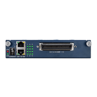
AAM1212 User’s Guide H A P T E R Hardware Connections This chapter describes the front panel and rear panel of the AAM and shows you how to make the hardware connections. 3.1 Front Panel The figure below shows the front panel of the AAM. -
Page 39: Console Port
AAM1212 User’s Guide Table 2 Front Panel LEDs Description (continued) COLOR STATUS DESCRIPTION Green Blinking The system is rebooting and performing self-diagnostic tests. The system is on and functioning properly. The power is off or the system is not ready/malfunctioning. -
Page 40: Notes About Mdfs (Main Distribution Frames)
AAM1212 User’s Guide Figure 8 Stacking Multiple IES-1000 Units 3.1.5 Notes About MDFs (Main Distribution Frames) An MDF is usually installed between end-users' equipment and the telephone company (CO) in a basement or telephone room. The MDF is the point of termination for the outside telephone company lines coming into a building and the telephone lines in the building. -
Page 41: Telco-50 Cables
AAM1212 User’s Guide Figure 9 MDF Wiring • Connect wiring from end-user equipment to the lower ports of an MDF using a telephone wire. Connect wiring from the telephone company to the upper ports of an MDF (see the previous figure). -
Page 42: Telco-50 Connections
AAM1212 User’s Guide Figure 10 Telco-50 Cable with RJ-11 Connectors 3.1.7 Telco-50 Connections The internal DSL splitters separate the voice signals from the DSL signals. They feed the DSL signals to the AAM and divert the voice signals to the CO lines of the Telco-50 connector. -
Page 43: Typical Mdf Scenarios
AAM1212 User’s Guide Figure 11 Installation Overview Note: You can also attach RJ-11 connectors to the Telco-50 cable and connect directly to a DSL modem(s) or patch panel. This chapter discusses connections using MDFs. 3.1.9 Typical MDF Scenarios This section describes typical installation scenarios. -
Page 44: Installation Scenario B
AAM1212 User’s Guide Figure 12 Installation Scenario A 3.1.9.1.1 Procedure To Connect To An MDF 1 Connect the Telco-50 connector end of the cable to the Telco-50 connector. 2 Connect the USER wiring on the other end of the Telco-50 cable to the upper ports of the MDF using a punch-down tool. -
Page 45: Figure 13 One Mdf For End-User And Co Connections
AAM1212 User’s Guide Figure 13 One MDF for End-user and CO Connections This installation scenario requires three MDFs. Please refer to the following figure for the connection schema. • MDF 1 is the original MDF used for telephone connections only. -
Page 46: Figure 14 Installation Scenario B
AAM1212 User’s Guide Figure 14 Installation Scenario B 3.1.9.2.1 Procedure To Connect To MDFs 1 Connect the Telco-50 connector end of the cable to the Telco-50 connector. 2 Connect the USER wiring on the other end of the Telco-50 cable to the upper ports of MDF 3 using a punch-down tool. -
Page 47: Installation Scenario C
AAM1212 User’s Guide 3.1.9.3 Installation Scenario C Phone service is also available but there are two MDFs; one for end-user telephone line connections and the other one for CO telephone wiring connections (see the following figure). Note: Users A and B have telephone (only) service. -
Page 48: Figure 16 Installation Scenario C
AAM1212 User’s Guide Figure 16 Installation Scenario C 3.1.9.3.1 Procedure To Connect To MDFs 1 Connect the Telco-50 connector end of the cable to the Telco-50 connector. 2 Connect the USER wiring on the other end of the Telco-50 cable to the upper ports of MDF 3 using a punch-down tool. - Page 49 AAM1212 User’s Guide Chapter 3 Hardware Connections...
-
Page 50: Web Configurator Introduction
AAM1212 User’s Guide H A P T E R Web Configurator Introduction This chapter tells how to access and navigate the web configurator. 4.1 Web Configurator Overview The web configurator allows you to use a web browser to manage the AAM. -
Page 51: Home Screen
AAM1212 User’s Guide Figure 17 Login Screen 4.3 Home Screen This is the web configurator's Home screen. Figure 18 Home Screen Click Home to view current device statistics. Click Logout to exit the web configurator. Navigation Panel Chapter 4 Web Configurator Introduction... -
Page 52: Table 3 Navigation Panel Sub-Links Overview
AAM1212 User’s Guide In the navigation panel, click a main link to reveal a list of submenu links. Click a submenu link to go to the corresponding screen. Table 3 Navigation Panel Sub-links Overview Basic Setting Advanced Application Routing Protocol... - Page 53 AAM1212 User’s Guide Table 4 Web Configurator Screens (continued) LINK DESCRIPTION Switch Setup Use this screen to set up global switch parameters such as IGMP snooping, MAC address learning, GARP and priority queues. IP Setup Use this screen to configure the system and management IP addresses and subnet masks.
-
Page 54: Saving Your Configuration
AAM1212 User’s Guide 4.4 Saving Your Configuration Click Apply in a configuration screen when you are done modifying the settings in that screen to save your changes back to the run time memory. Settings in the run time memory are lost when the AAM's power is turned off. - Page 55 AAM1212 User’s Guide Chapter 4 Web Configurator Introduction...
-
Page 56: Initial Configuration
AAM1212 User’s Guide H A P T E R Initial Configuration This chapter describes initial configuration for the AAM. 5.1 Initial Configuration Overview This chapter shows what you first need to do to provide service to ADSL subscribers. 5.2 Initial Configuration This chapter uses the web configurator for initial configuration. -
Page 57: Figure 22 Basic Setting Ip Setup Menu
AAM1212 User’s Guide Figure 22 Basic Setting IP Setup Menu 5 Use this screen to change the IP address, subnet mask, and default gateway IP address for your network. Apply the settings. If you change the AAM’s IP address, you must use the new IP address if you want to access the web configurator again. -
Page 58: Figure 24 Basic Setting Xdsl Port Setup Menu
AAM1212 User’s Guide Figure 24 Basic Setting xDSL Port Setup Menu 8 Click VC Setup. Figure 25 xDSL Port Setup 9 Click a virtual channel's Select radio button and click Delete. Click OK in the next screen. Chapter 5 Initial Configuration... -
Page 59: Figure 26 Deleting A Pvc
AAM1212 User’s Guide Figure 26 Deleting a PVC 10 Click All and then Apply. Figure 27 Select Ports 11 Select Super Channel to allow the channel to forward frames belonging to multiple VLAN groups (that are not assigned to other channels). Enter the VPI and VCI that you need. -
Page 60: Figure 28 Adding A New Channel
AAM1212 User’s Guide Figure 28 Adding a New Channel 12 Click the new channel's Select radio button. Click Copy and then Paste. Figure 29 Copying the PVC 13 Click All to select every port. 14 Click Apply to paste the settings. -
Page 61: Default Settings
AAM1212 User’s Guide Figure 31 Config Save Menu 16 Click Save. Figure 32 Config Save Screen You can now use the device (with the other settings set to the defaults) to provide service to ADSL subscribers. See the rest of this chapter for information on other default settings. - Page 62 AAM1212 User’s Guide Table 5 Default Settings Target SNR 6 db 6 db Name: DEFVAL_MAX Profile Status: Active Latency Mode: Interleave Upstream ADSL Settings: Downstream ADSL Settings: Max Rate 512 Kbps 9088 Kbps Min Rate 32 Kbps 32 Kbps Interleave Delay...
- Page 63 AAM1212 User’s Guide Chapter 5 Initial Configuration...
-
Page 64: Home And Port Statistics Screens
AAM1212 User’s Guide H A P T E R Home and Port Statistics Screens This chapter describes the Home (status) and Port Statistics screens. 6.1 Home and Port Statistics Screens Overview The Home screen of the web configurator displays a port statistical summary with links to each port for showing statistical details. -
Page 65: Ethernet Port Statistics
AAM1212 User’s Guide The following table describes the labels in this screen. Table 6 Home LABEL DESCRIPTION System up Time This field shows how long the system has been running since the last time it was started. The following fields are related to the Ethernet ports. -
Page 66: Figure 34 Ethernet Port Statistics
AAM1212 User’s Guide Figure 34 Ethernet Port Statistics The following table describes the labels in this screen. Table 7 Ethernet Port Statistics LABEL DESCRIPTION Return Click this link to go back to the Home screen. Port Use this drop-down list box to select a port for which you wish to view statistics. - Page 67 AAM1212 User’s Guide Table 7 Ethernet Port Statistics (continued) LABEL DESCRIPTION Rx mac pause This field shows the number of valid IEEE 802.3x Pause frames received on this port. Rx fragments This field shows the number of frames received that were less than 64 octets long, and contained an invalid FCS, including non-integral and integral lengths.
-
Page 68: Adsl Port Statistics
AAM1212 User’s Guide Table 7 Ethernet Port Statistics (continued) LABEL DESCRIPTION packet(128-255) This field shows the number of frames received and transmitted (including bad frames) that were 128 to 255 octets in length (this includes FCS octets but excludes framing bits). -
Page 69: Figure 35 Adsl Port Statistics
AAM1212 User’s Guide Figure 35 ADSL Port Statistics The following table describes the labels in this screen. Table 8 ADSL Port Statistics LABEL DESCRIPTION Return Click this link to go back to the Home screen. xDSL Port Use this drop-down list box to select a port for which you wish to view statistics. - Page 70 AAM1212 User’s Guide Table 8 ADSL Port Statistics (continued) LABEL DESCRIPTION Tx bytes This field shows the number of kilobytes that have been transmitted on this port. Rx bytes This field shows the number of kilobytes that have been received on this port.
- Page 71 AAM1212 User’s Guide Chapter 6 Home and Port Statistics Screens...
-
Page 72: Basic Setting Screens
AAM1212 User’s Guide H A P T E R Basic Setting Screens This chapter describes how to configure the System Information, General Setup, Switch Setup, IP Setup and ENET Port Setup screens. 7.1 Basic Setting Screens Overview The System Information screen displays general AAM information (such as firmware version number) and hardware polling information (such as fan status). -
Page 73: Figure 36 System Information
AAM1212 User’s Guide Figure 36 System Information The following table describes the labels in this screen. Table 9 System Information LABEL DESCRIPTION System Name This field displays the AAM's model name. ZyNOS F/W This field displays the version number of the AAM’s current firmware including the Version date created. -
Page 74: General Setup
AAM1212 User’s Guide Table 9 System Information (continued) LABEL DESCRIPTION Temperature- C Each temperature sensor can detect and report the temperature. Temperature sensor 1 is near the ADSL line driver. Temperature sensor 2 is near the ADSL chipset. Temperature sensor 3 is near the central processing unit. -
Page 75: Figure 37 General Setup
AAM1212 User’s Guide Figure 37 General Setup The following table describes the labels in this screen. Table 10 General Setup LABEL DESCRIPTION Host Name Choose a descriptive name for identification purposes. This name consists of up to 31 ASCII characters; spaces are not allowed. -
Page 76: Igmp Snooping
AAM1212 User’s Guide Table 10 General Setup (continued) LABEL DESCRIPTION Current Date This field displays the date you open this menu. New Date (yyyy- Enter the new date in year, month and day format. The new date then appears in mm-dd) the Current Date field after you click Apply. -
Page 77: Port Isolation With Standalone Switch Mode Example
AAM1212 User’s Guide for an example). When the AAM is in standalone mode, you can use it in a network topology that uses loops (you should also enable RSTP). You can have multiple AAMs connected on the same network and set both of them to use standalone mode in order to use them with a network topology that uses loops. -
Page 78: Daisychain Switch Mode
AAM1212 User’s Guide 7.5.3 Daisychain Switch Mode Daisychain switch mode sets the AAM to use Ethernet port one (LAN 1) as an uplink port to connect to the Ethernet backbone and Ethernet port two (LAN 2) to connect to another (daisychained or subtending) AAM. -
Page 79: Switch Setup Screen
AAM1212 User’s Guide 7.6 Switch Setup Screen Click Basic Setting and then Switch Setup in the navigation panel to display the screen as shown. Figure 40 Switch Setup The following table describes the labels in this screen. Table 11 Switch Setup... - Page 80 AAM1212 User’s Guide Table 11 Switch Setup (continued) LABEL DESCRIPTION Leave All Timer Leave All Timer sets the duration of the Leave All Period timer for GVRP in milliseconds. Each port has a single Leave All Period timer. Leave All Timer must be larger than Leave Timer;...
-
Page 81: Ip Setup
AAM1212 User’s Guide 7.7 IP Setup Click Basic Setting and then IP Setup in the navigation panel to display the screen as shown. Use this screen to configure the system and management IP addresses and subnet masks. Figure 41 IP Setup The following table describes the labels in this screen. -
Page 82: Figure 42 Enet Port Setup
AAM1212 User’s Guide Figure 42 ENET Port Setup The following table describes the fields in this screen. Table 13 ENET Port Setup LABEL DESCRIPTION Port This is the port index number. Active Select this check box to enable a port. The factory default for all ports is enabled. A port must be enabled for data transmission to occur. - Page 83 AAM1212 User’s Guide Chapter 7 Basic Setting Screens...
-
Page 84: Chapter 8 Adsl Port Setup
AAM1212 User’s Guide H A P T E R ADSL Port Setup This chapter explains how to configure settings for profiles and individual ADSL ports. It also covers how to configure virtual channels and virtual channel profiles. 8.1 ADSL Standards Overview These are the ADSL standards and rates that the AAM supports at the time of writing. -
Page 85: Interleave Delay
AAM1212 User’s Guide For example, you could set up different profiles for different kinds of accounts (for example, economy, standard and premium). Assign the appropriate profile to an ADSL port and it takes care of a large part of the port's configuration maximum and minimum transfer rates. You still get to individually enable or disable each port, as well as configure its channels and operational mode. -
Page 86: Default Settings
AAM1212 User’s Guide 8.6 Default Settings The default profile always exists and all of the ADSL ports use the default profile settings when the AAM is shipped. The default profile's name is set to DEFVAL. The default profile's maximum downstream rate can only be obtained when using the G.dmt standard. Configure a profile with a maximum downstream rate of 1536 Kbps or less for use with G.lite. -
Page 87: Table 15 Xdsl Port Setup
AAM1212 User’s Guide The following table describes the fields in this screen. Table 15 xDSL Port Setup LABEL DESCRIPTION VC Setup Click VC Setup to open the VC Setup screen where you can configure VC settings for the DSL ports. -
Page 88: Xdsl Port Setting
AAM1212 User’s Guide Table 15 xDSL Port Setup (continued) LABEL DESCRIPTION Packet Filter Select this check box to copy this port’s packet filter settings. These are configured in the Packet Filtering screen (see the chapter on packet filtering). Port This field shows the port index number. -
Page 89: Virtual Channels
AAM1212 User’s Guide The following table describes the fields in this screen. Table 16 xDSL Port Setting LABEL DESCRIPTION Last Page Click this to return to the previous screen. Active Select this check box to turn on this ADSL port. -
Page 90: Super Channel
AAM1212 User’s Guide For example, you want to give high priority to voice service on one of the ADSL ports. First configure a static VLAN on the AAM for voice on the port. Then do the following: • Configure a channel on the port for voice service. -
Page 91: Vc Setup Screen
AAM1212 User’s Guide 8.9 VC Setup Screen Click Basic Setting and then xDSL Port Setup in the navigation panel and then the VC Setup link to open the following screen. Use this screen to view and configure a port's channel (PVC) settings. - Page 92 AAM1212 User’s Guide Table 17 VC Setup LABEL DESCRIPTION VC Profile Use the drop-down list box to select a VC profile to assign to this channel. PVID Type a PVID (Port VLAN ID) to assign to untagged frames received on this channel.
- Page 93 AAM1212 User’s Guide Table 17 VC Setup LABEL DESCRIPTION Delete Do the following to remove one or more PVCs. 1. Select a PVC’s Select radio button. 2. Click Delete. 3. Click OK if you want to remove the PVC from other ports. Click Cancel to only remove the one you selected.
-
Page 94: Port Profile Screen
AAM1212 User’s Guide Table 17 VC Setup LABEL DESCRIPTION Copy, Paste Do the following to copy settings from one PVC to another port or ports. 1. Click the Select radio button of the PVC from which you want to copy settings. -
Page 95: Figure 46 Port Profile
AAM1212 User’s Guide Figure 46 Port Profile The following table describes the fields in this screen. Table 18 Port Profile LABEL DESCRIPTION VC Profile Click VC Profile to open the VC Profile screen where you can configure virtual channel profiles. - Page 96 AAM1212 User’s Guide Table 18 Port Profile (continued) LABEL DESCRIPTION Latency Mode This field sets the ADSL latency mode for the ports that belong to this profile. Select Fast mode to use no interleaving and have faster transmission (a “fast channel”).
-
Page 97: Atm Qos
AAM1212 User’s Guide 8.11 ATM QoS ATM Quality of Service (QoS) mechanisms provide the best service on a per-flow guarantee. ATM network infrastructure was designed to provide QoS. It uses fixed cell sizes and built-in traffic management (see the following section on traffic shaping). This allows you to fine-tune the levels of services on the priority of the traffic flow. -
Page 98: Unspecified Bit Rate (Ubr)
AAM1212 User’s Guide 8.12.1.3 Unspecified Bit Rate (UBR) The Unspecified Bit Rate (UBR) ATM traffic class is similar to the ABR traffic class for bursty data transfers. However, while ABR gives subscribers a set amount of bandwidth, UBR doesn't guarantee any bandwidth and only delivers traffic when the network has spare bandwidth. -
Page 99: Cell Delay Variation Tolerance (Cdvt)
AAM1212 User’s Guide Figure 47 PCR, SCR, MCR and MBS in Traffic Shaping 8.12.2.5 Cell Delay Variation Tolerance (CDVT) Cell Delay Variation Tolerance (CDVT) is the accepted tolerance of the difference between a cell's transfer delay and the expected transfer delay. CDVT controls the time scale over which the PCR is enforced. -
Page 100: Vc Profile Screen
AAM1212 User’s Guide 8.13 VC Profile Screen Click Basic Setting and then xDSL Profiles Setup in the navigation panel and then VC Profile to open the following screen. Figure 49 VC Profile The following table describes the fields in this screen. -
Page 101: Alarm Profile Screen
AAM1212 User’s Guide Table 19 VC Profile (continued) LABEL DESCRIPTION Burst Tolerance (BT) is the maximum number of cells that the port is guaranteed to handle without any discards. BT applies with the vbr traffic class. Modify Select a VC profile’s Select radio button and click Modify to edit the VC profile. -
Page 102: Figure 50 Alarm Profile
AAM1212 User’s Guide Figure 50 Alarm Profile The following table describes the fields in this screen. Table 20 Alarm Profile LABEL DESCRIPTION Port Profile Click Port Profile to open the Port Profile screen. Use the Port Profile screen to configure profiles of ADSL port settings (such as the transfer rate, interleave delay and signal to noise ratio settings). -
Page 103: Igmp Filter Profile Screen
AAM1212 User’s Guide Table 20 Alarm Profile (continued) LABEL DESCRIPTION 15 Min LOS This field sets the limit for the number of Loss Of Signal seconds that are permitted (sec) to occur within 15 minutes. 15 Min LOL This field sets limit for the number of Loss Of Link seconds that are permitted to (sec) occur within 15 minutes. -
Page 104: Figure 51 Igmp Filter Profile
AAM1212 User’s Guide The DEFVAL IGMP filter profile is assigned to all of the ADSL ports by default. It allows a port to join all multicast IP addresses (224.0.0.0~239.255.255.255). If you want to allow an ADSL subscriber access to only specific IGMP multicast groups, use the IGMP Filter Profile... -
Page 105: Line Rate Information
AAM1212 User’s Guide Table 21 IGMP Filter Profile (continued) LABEL DESCRIPTION Index This is the number of the IGMP filter profile. Click a profile’s index number to edit the profile. You cannot edit the DEFVAL profile. Name This name identifies the IGMP filter profile. -
Page 106: Table 22 Line Rate Information
AAM1212 User’s Guide The following table describes the fields in this screen. Table 22 Line Rate Information LABEL DESCRIPTION Line Performance Click Line Performance to display an ADSL port’s line performance counters. Line Data Click Line Data to display an ADSL port’s line bit allocation. -
Page 107: Line Performance
AAM1212 User’s Guide 8.17 Line Performance Click Basic Setting and then Line Data in the navigation panel and then the Line Performance link to open the following screen. This screen displays an ADSL port's line performance counters. These counters display line performance data that has been accumulated since the system started. -
Page 108: Line Data
AAM1212 User’s Guide Table 23 Line Performance (continued) LABEL DESCRIPTION Down/Up Stream The number of Blocks transmitted (downstream) or received (upstream) on this BLKS ADSL port. A block is a set of consecutive bits associated with the path; each bit belongs to one and only one block. -
Page 109: Figure 54 Line Data
AAM1212 User’s Guide Discrete Multi-Tone (DMT) modulation divides up a line's bandwidth into tones. This screen displays the number of bits transmitted for each tone. This can be used to determine the quality of the connection, whether a given sub-carrier loop has sufficient margins to support ADSL transmission rates, and possibly to determine whether certain specific types of interference or line attenuation exist. -
Page 110: Table 24 Line Data
AAM1212 User’s Guide The following table describes the fields in this screen. Table 24 Line Data LABEL DESCRIPTION Line Rate Click Line Rate to display an ADSL port’s line operating values. Line Performance Click Line Performance to display an ADSL port’s line performance counters. - Page 111 AAM1212 User’s Guide Chapter 8 ADSL Port Setup...
-
Page 112: Chapter 9 Vlan
AAM1212 User’s Guide H A P T E R VLAN This chapter shows you how to configure 802.1Q tagged VLANs. 9.1 Introduction to VLANs A VLAN (Virtual Local Area Network) allows a physical network to be partitioned into multiple logical networks. Devices on a logical network belong to one group. A device can belong to more than one group. -
Page 113: Forwarding Tagged And Untagged Frames
AAM1212 User’s Guide priority frame, meaning that only the priority level is significant and the default VID of the ingress port is given as the VID of the frame. Of the 4096 possible VIDs, a VID of 0 is used to identify priority frames and value 4095 (FFF) is reserved, so the maximum possible VLAN configurations are 4,094. -
Page 114: Garp Timers
AAM1212 User’s Guide 9.3.1.1 GARP Timers Switches join VLANs by making a declaration. A declaration is made by issuing a Join message using GARP. Declarations are withdrawn by issuing a Leave message. A Leave All message terminates all registrations. GARP timers set declaration timeout values. -
Page 115: Figure 55 Vlan Status
AAM1212 User’s Guide Figure 55 VLAN Status The following table describes the labels in this screen. Table 26 VLAN Status LABEL DESCRIPTION Static VLAN Click Static VLAN Setting to configure ports to dynamically join a VLAN group or Setting permanently assign ports to a VLAN group or prohibit ports from joining a VLAN group. -
Page 116: Static Vlan Setting
AAM1212 User’s Guide 9.5 Static VLAN Setting Click Advanced and then VLAN in the navigation panel and then the Static VLAN Setting link to display the screen as shown next. You can assign a port to be a member of a VLAN group or prohibit a port from joining a VLAN group in this screen. -
Page 117: Vlan Port Setting
AAM1212 User’s Guide Table 27 Static VLAN Setting (continued) LABEL DESCRIPTION Delete Select the check boxes of the rules that you want to remove in the Delete column and then click the Delete button. You cannot delete a VLAN if any PVIDs are set to use the VLAN or the VLAN is the CPU (management) VLAN. -
Page 118: Figure 57 Vlan Port Setting
AAM1212 User’s Guide Figure 57 VLAN Port Setting The following table describes the labels in this screen. Table 28 VLAN Port Setting LABEL DESCRIPTION VLAN Status Click VLAN Status to see which of the AAM’s ports are members of which VLANs. - Page 119 AAM1212 User’s Guide Table 28 VLAN Port Setting (continued) LABEL DESCRIPTION Cancel Click Cancel to begin configuring this screen afresh. Copy port Do the following to copy settings from one port to another port or ports. 1. Select the number of the port from which you want to copy settings.
-
Page 120: Chapter 10 Igmp Snooping
AAM1212 User’s Guide H A P T E R IGMP Snooping This chapter describes the IGMP Snooping screen. 10.1 IGMP Snooping IGMP (Internet Group Multicast Protocol) is a session-layer protocol used to establish membership in a multicast group - it is not used to carry user data. Refer to RFC 1112 and RFC 2236 for information on IGMP versions 1 and 2 respectively. -
Page 121: Table 29 Igmp Snooping
AAM1212 User’s Guide The following table describes the labels in this screen. Table 29 IGMP Snooping LABEL DESCRIPTION Query This is the total number of Query packets received. Report This is the total number of Report packets received. Leave This is the total number of Leave packets received. -
Page 122: Chapter 11 Static Multicast
AAM1212 User’s Guide H A P T E R Static Multicast This chapter describes the Static Multicast screen. 11.1 Static Multicast Filter Use the static multicast filter to allow incoming frames based on multicast MAC address(es) that you specify. This feature can be used in conjunction with IGMP snooping to allow multicast MAC address(es) that are not learned by IGMP snooping. - Page 123 AAM1212 User’s Guide Table 30 Static Multicast (continued) LABEL DESCRIPTION The first table displays the names of the fields. The subsequent tables show the settings of the IGMP groups. Index This is the static multicast group index number. MAC Address This is the multicast MAC address.
-
Page 124: Chapter 12 Packet Filtering
AAM1212 User’s Guide H A P T E R Packet Filtering This chapter describes how to configure the Packet Filter screen. 12.1 Packet Filter Configuration Click Advanced Application and then Filtering in the navigation panel to display the Packet Filter screen as shown next. Use this screen to set which types of packets the AAM accepts on individual ADSL ports. - Page 125 AAM1212 User’s Guide Table 31 Packet Filter (continued) LABEL DESCRIPTION PPPoE Only Select this check box to allow only PPPoE traffic. This will gray out the check boxes for other packet types and the AAM will drop any non-PPPoE packets.
-
Page 126: Chapter 13 Mac Filter
AAM1212 User’s Guide H A P T E R MAC Filter This chapter introduces the MAC filter. 13.1 MAC Filter Introduction Use the MAC filter to allow only frames from MAC (Media Access Control) address(es) that you specify to come in through a port. -
Page 127: Table 32 Mac Filter
AAM1212 User’s Guide The following table describes the labels in this screen. Table 32 MAC Filter LABEL DESCRIPTION Port Use this drop-down list box to select an ADSL port for which you wish to configure MAC filtering. Type a device’s MAC address in hexadecimal notation (xx:xx:xx:xx:xx:xx, where x is a number from 0 to 9 or a letter from a to f) in this field. -
Page 128: Spanning Tree Protocol
AAM1212 User’s Guide H A P T E R Spanning Tree Protocol This chapter introduces the Rapid Spanning Tree Protocol (RSTP). 14.1 RSTP (Rapid Spanning Tree Protocol) and STP (Spanning Tree Protocol) RSTP adds rapid reconfiguration capability to STP. The switch supports RSTP and the earlier STP. -
Page 129: Figure 62 Stp Root Ports And Designated Ports
AAM1212 User’s Guide After a bridge determines the lowest cost-spanning tree with RSTP, it enables the root port and the ports that are the designated ports for the connected LANs, and disables all other ports that participate in RSTP. Network packets are therefore only forwarded between enabled ports, eliminating any possible network loops. -
Page 130: Stp Status
AAM1212 User’s Guide Table 34 RSTP Port States RSTP PORT STP PORT DESCRIPTION STATE STATE Learning Learning All BPDUs are received and processed. Information frames are submitted to the learning process but not forwarded. Forwarding Forwarding All BPDUs are received and processed. All information frames are received and forwarded. - Page 131 AAM1212 User’s Guide Table 35 Spanning Tree Protocol: Status (continued) LABEL DESCRIPTION Our bridge ID This is the unique identifier for this bridge, consisting of bridge priority plus MAC address. This ID is the same in Designated root ID if the AAM is the root switch.
-
Page 132: Configure Stp
AAM1212 User’s Guide 14.2.1 Configure STP Click Advanced Application and then Spanning Tree Protocol in the navigation panel to display the STP status. Click STP Config to display the Spanning Tree Protocol Configuration screen as shown next. Figure 64 Spanning Tree Protocol: Configuration The following table describes the labels in this screen. - Page 133 AAM1212 User’s Guide Table 36 Spanning Tree Protocol: Configuration (continued) LABEL DESCRIPTION MAX Age This is the maximum time (in seconds) a switch can wait without receiving a BPDU before attempting to reconfigure. All switch ports (except for designated ports) should receive BPDUs at regular intervals.
-
Page 134: Chapter 15 Port Authentication
AAM1212 User’s Guide H A P T E R Port Authentication This chapter describes the 802.1x authentication method and RADIUS server connection setup. 15.1 Introduction to Authentication IEEE 802.1x is an extended authentication protocol that allows support of RADIUS (Remote Authentication Dial In User Service, RFC 2138, 2139) for centralized user profile management on a network RADIUS server. -
Page 135: Figure 66 Port Authentication: Radius
AAM1212 User’s Guide Figure 66 Port Authentication: RADIUS The following table describes the labels in this screen. Table 37 Port Authentication: RADIUS LABEL DESCRIPTION 802.1x Click 802.1x to configure individual port authentication settings. Enable Select this check box to have the AAM use an external RADIUS server to Authentication authenticate users. -
Page 136: Eee802.1X Configuration
AAM1212 User’s Guide Table 37 Port Authentication: RADIUS (continued) (continued) LABEL DESCRIPTION Cancel Click Cancel to begin configuring this screen afresh. This table displays the configured user profiles. Index These are the numbers of the user profiles. Click this number to edit the user profile. -
Page 137: Table 38 Port Authentication: 802.1X
AAM1212 User’s Guide The following table describes the labels in this screen. Table 38 Port Authentication: 802.1x LABEL DESCRIPTION RADIUS/Local Click this link to configure the RADIUS server or local profile settings. Profile Enable Select this check box to turn on IEEE 802.1x authentication on the AAM. -
Page 138: Chapter 16 Port Security
AAM1212 User’s Guide H A P T E R Port Security This chapter shows you how to set up port security. 16.1 About Port Security Port security allows you to restrict the number of MAC addresses that can be learned on a port. -
Page 139: Table 39 Port Security
AAM1212 User’s Guide The following table describes the labels in this screen. Table 39 Port Security LABEL DESCRIPTION Port This field displays a port number. Enable Select this check box to restrict the number of MAC addresses that can be learned on the port. -
Page 140: Chapter 17 Dhcp Relay
AAM1212 User’s Guide H A P T E R DHCP Relay This chapter shows you how to set up DHCP relay. 17.1 DHCP Relay Overview DHCP (Dynamic Host Configuration Protocol, RFC 2131 and RFC 2132) allows individual clients to obtain TCP/IP configuration at start-up from a DHCP server. You can configure the AAM to relay client TCP/IP configuration requests to a DHCP server and the server's responses back to the clients. -
Page 141: Figure 69 Dhcp Relay
AAM1212 User’s Guide Figure 69 DHCP Relay The following table describes the labels in this screen. Table 40 DHCP Relay LABEL DESCRIPTION Enable DHCP Enable DHCP relay to have the AAM relay client TCP/IP configuration requests to relay a DHCP server and the server’s responses back to the clients. -
Page 142: Chapter 18 Syslog
AAM1212 User’s Guide H A P T E R Syslog This chapter explains how to set the syslog parameters. 18.1 Syslog The syslog feature sends logs to an external syslog server. 18.2 Syslog Setup Click Advanced Application and then SysLog in the navigation panel to display the screen shown next. - Page 143 AAM1212 User’s Guide Chapter 18 Syslog...
-
Page 144: Chapter 19 Access Control
AAM1212 User’s Guide H A P T E R Access Control This chapter describes how to configure access control. 19.1 About Access Control Click Advanced Application and then Access Control from the navigation panel to display the screen as shown. From this screen you can configure SNMP and enable/disable remote service access. -
Page 145: About Snmp
AAM1212 User’s Guide 19.3 About SNMP Simple Network Management Protocol is a protocol used for exchanging management information between network switches. SNMP is a member of TCP/IP protocol suite. A manager station can manage and monitor the AAM through the network via SNMP version one (SNMPv1) and/or SNMP version 2c. -
Page 146: Supported Mibs
AAM1212 User’s Guide SNMP itself is a simple request/response protocol based on the manager/agent model. The manager issues a request and the agent returns responses using the following protocol operations: Table 43 SNMP Commands COMMAND DESCRIPTION Allows the manager to retrieve an object variable from the agent. -
Page 147: Zyxel Private Mib Snmp Traps
AAM1212 User’s Guide Table 44 RFC-1215 SNMP Traps GENERIC SPECIFIC TRAP DESCRIPTION TRAP TRAP sendLinkUpTrap This trap is sent when the Ethernet or ADSL link is up. sendAuthFailTrap This trap is sent when an SNMP request comes from non-authenticated hosts. -
Page 148: Setting Up The Administrator Login Account
AAM1212 User’s Guide The following table describes the labels in this screen. Table 46 Access Control: SNMP LABEL DESCRIPTION Return Click Return to go back to the previous screen. Get Community Enter the get community, which is the password for the incoming Get- and GetNext- requests from the management station. -
Page 149: Service Access Control Configuration
AAM1212 User’s Guide The following table describes the labels in this screen. Table 47 Access Control: Logins LABEL DESCRIPTION Return Click Return to go back to the previous screen. Administrator This is the default administrator account with the “admin” user name. You cannot change the default administrator user name. -
Page 150: Secured Client Configuration
AAM1212 User’s Guide Table 48 Access Control: Service Access Control (continued) (continued) LABEL DESCRIPTION Apply Click Apply to save your changes to the AAM’s volatile memory. The AAM loses these changes if it is turned off or loses power, so use the Config Save link on the navigation panel to save your changes to the non-volatile memory when you are done configuring. - Page 151 AAM1212 User’s Guide Chapter 19 Access Control...
-
Page 152: Chapter 20 Routing Protocol
AAM1212 User’s Guide H A P T E R Routing Protocol This chapter shows you how to configure the static routing function. 20.1 Static Route Static routes tell the AAM how to forward the AAM’s own IP traffic when you configure the TCP/IP parameters manually. -
Page 153: Figure 79 Static Routing: Summary Table
AAM1212 User’s Guide Table 50 Static Routing (continued) LABEL DESCRIPTION Gateway IP Enter the IP address of the gateway. The gateway is an immediate neighbor of your Address AAM that will forward the packet to the destination. The gateway must be a router on the same segment as your AAM. -
Page 154: Chapter 21 Maintenance
AAM1212 User’s Guide H A P T E R Maintenance This chapter explains how to use the maintenance screens. 21.1 Maintenance Click Management and then Maintenance in the navigation panel to open the following screen. Figure 80 Maintenance 21.2 Firmware Upgrade From the Maintenance screen, use Firmware Upgrade to upgrade your AAM firmware. -
Page 155: Restore A Text Configuration File
AAM1212 User’s Guide Figure 81 Firmware Upgrade Type the path and file name of the firmware file you wish to upload to the AAM in the File Path text box or click Browse to locate it. After you have specified the file, click Upgrade. -
Page 156: Load Factory Defaults
AAM1212 User’s Guide 1 Right-click the Backup Text Configuration Click here link and click Save Target As. Click the Backup Text Configuration Click Here link and then click Save. 2 In the Save As screen, choose a location to save the file on your computer from the Save in drop-down list box and type a descriptive name for it in the File name list box. -
Page 157: Command Line Ftp
AAM1212 User’s Guide Click OK. You then see the screen as shown in Figure 84 on page 155. Click OK again and wait for the AAM to restart. This takes up to two minutes. This does not affect the AAM's configuration. -
Page 158: Chapter 22 Diagnostic
AAM1212 User’s Guide H A P T E R Diagnostic This chapter explains the Diagnostic screen. 22.1 Diagnostic Click Management and then Diagnostic in the navigation panel to display this screen. Use this screen to check system logs, ping IP addresses or perform loopback tests. -
Page 159: Log Format
AAM1212 User’s Guide The following table describes the labels in this screen. Table 52 Diagnostic LABEL DESCRIPTION Syslog/ Event Log Click Display to display a log of events in the multi-line text box. Click Clear to empty the text box and reset the syslog entry. -
Page 160: Log Messages
AAM1212 User’s Guide 22.2.1 Log Messages The following table lists and describes the system log messages. Table 54 Log Messages LOG MESSAGE TYPE DESCRIPTION ADSL <port> Link An ADSL port established a connection. INFO Up(SN=<seq no>): <port> - port number <ds rate>/<us... -
Page 161: Line Diagnostics Test Parameters
AAM1212 User’s Guide Table 54 Log Messages LOG MESSAGE TYPE DESCRIPTION The voltage went outside of the accepted operating range. THERMO OVER WARN VOLTAGE: <nominal> - nominal voltage of the DC power nominal:<nominal>( <voltage> - voltage of the DC power when logged value:<voltage>... - Page 162 AAM1212 User’s Guide Table 55 Line Diagnostics Test Parameters LABEL DESCRIPTION This is a format for providing channel characteristics. It provides magnitude values in a logarithmic scale. This can be used in analyzing the physical condition of the ADSL line.
- Page 163 AAM1212 User’s Guide Chapter 22 Diagnostic...
-
Page 164: Chapter 23 Mac Table
AAM1212 User’s Guide H A P T E R MAC Table This chapter introduces the MAC Table screen. 23.1 Introduction to MAC Table The MAC table lists device MAC addresses that are dynamically learned by the AAM. The table shows the following for each MAC address: the port upon which Ethernet frames were received from the device, to which VLAN groups the device belongs (if any) and to which channel it is connected (for devices connected to DSL ports). -
Page 165: Viewing The Mac Table
AAM1212 User’s Guide 23.2 Viewing the MAC Table Click Management in the navigation panel and then MAC Table to display the following screen. Figure 88 MAC Table The following table describes the labels in this screen. Table 56 MAC Table... -
Page 166: Chapter 24 Arp Table
AAM1212 User’s Guide H A P T E R ARP Table This chapter introduces the ARP table. 24.1 Introduction to ARP Table Address Resolution Protocol (ARP) is a protocol for mapping an Internet Protocol address (IP address) to a physical machine address, also known as a Media Access Control or MAC address, on the local area network. -
Page 167: Figure 89 Arp Table
AAM1212 User’s Guide Figure 89 ARP Table The following table describes the labels in this screen. Table 57 ARP Table LABEL DESCRIPTION Flush Click Flush to remove all of the entries from the ARP table. Total X ARP This displays the number of entries in the ARP table. -
Page 168: Chapter 25 Commands Overview
AAM1212 User’s Guide H A P T E R Commands Overview This chapter introduces the command line interface and lists the available commands. 25.1 Command Line Interface Note: See the web configurator parts of this User’s Guide for background information on features configurable by web configurator. -
Page 169: Commands Summary
AAM1212 User’s Guide 25.2 Commands Summary The following table lists commands that you can use with the AAM. Table 58 Commands COMMAND DESCRIPTION info Displays general system information. show Sets the system name. hostname <hostname> Sets location information. location <location>... - Page 170 AAM1212 User’s Guide Table 58 Commands (continued) COMMAND DESCRIPTION Stops a secured client set from disable <index> managing the device. Sets a secured client set: a range of IP <index> <start addresses from which you can ip> <end ip> manage the device and the protocols [[telnet] [ftp] that can be used.
- Page 171 AAM1212 User’s Guide Table 58 Commands (continued) COMMAND DESCRIPTION Sets the watchdog count. 0 turns the <msec|0:disable watchdog off. > monitor Displays the hardware monitor’s show statistics. Turns the hardware monitor on. enable Turns the hardware monitor off. disable Sets the maximum (<high>) or vlimit <idx>...
- Page 172 AAM1212 User’s Guide Table 58 Commands (continued) COMMAND DESCRIPTION Creates an ADSL profile. <profile> <fast| interleave [=<up delay>,<down delay>]> <up max rate> <down max rate> [<up target margin> <up min margin> <up max margin> <up min rate> <down target margin> <down min margin>...
- Page 173 AAM1212 User’s Guide Table 58 Commands (continued) COMMAND DESCRIPTION Creates or modifies a PVC setting. <portlist> <vpi> <vci> <super |vid = 1..4094 <priority>> <vcprofile> Removes a PVC setting. delete <portlist> <vpi> <vci> Displays all ADSL configuration. showall [nopause] linediag Sets the specified port to line setld <port number>...
- Page 174 AAM1212 User’s Guide Table 58 Commands (continued) COMMAND DESCRIPTION Maps specified ADSL ports to an <portlist> alarm profile. <profile> Displays alarm profile to ADSL port showmap [profile] mapping. Displays which alarm profile showport [port] parameters are mapped to an ADSL port.
- Page 175 AAM1212 User’s Guide Table 58 Commands (continued) COMMAND DESCRIPTION Removes an IGMP filter profile. delete <name> Displays an IGMP filter profile’s show [name] settings. queuemap Displays the system’s priority level to show physical queue mapping. Maps a priority level to a physical <priority>...
- Page 176 AAM1212 User’s Guide Table 58 Commands (continued) COMMAND DESCRIPTION option82 Turns on the DHCP relay agent enable information (Option 82) feature. Turns off the DHCP relay agent disable information (Option 82) feature. Adds the specified information for the set <relay relay agent.
- Page 177 AAM1212 User’s Guide Table 58 Commands (continued) COMMAND DESCRIPTION Displays the system’s current MAC show address count settings. [portlist] Turns on the MAC address count filter enable for a port(s). <portlist> Turns off the MAC address count filter disable for a port(s).
- Page 178 AAM1212 User’s Guide Table 58 Commands (continued) COMMAND DESCRIPTION Turns off IEEE 802.1X for specific disable ports. <portlist> Sets the IEEE 802.1X port control authentication option for specific ports. <portlist> <auto|auth|unau th> Sets the IEEE 802.1X re- reauth authentication option for specific ports.
- Page 179 AAM1212 User’s Guide Table 58 Commands (continued) COMMAND DESCRIPTION Use join/leave to add/ remove <adsl_port> multicast MAC addresses (up to ten) <mac> on specified ADSL ports, a range of <join|leave> ADSL ports or all ADSL ports. MAC example: 01005E010203 Removes a static multicast filter entry delete <mac>...
- Page 180 AAM1212 User’s Guide Table 58 Commands (continued) COMMAND DESCRIPTION Displays all of the AAM’s IP showall [nopause] configuration. statisti Displays hardware monitor statistics. monitor adsl Displays ADSL port connection show [portlist] statistics. Displays the line data load per symbol linedata <portlist>...
- Page 181 AAM1212 User’s Guide Chapter 25 Commands Overview...
-
Page 182: Chapter 26 Sys Commands
AAM1212 User’s Guide H A P T E R Sys Commands This chapter describes the commonly used commands that belong to the sys (system) group of commands. 26.1 Sys Commands Summary The following table lists the commands you can use with the AAM. -
Page 183: Table 59 Sys Commands
AAM1212 User’s Guide Table 59 Sys Commands (continued) COMMAND DESCRIPTION Turns on a service. enable <telnet|ftp|web |icmp> Turns off a service. disable <telnet|ftp|web |icmp> Sets a port for a service. port <telnet|ftp|web > <port> client Displays the device’s secured client show settings. -
Page 184: Sys Command Examples
AAM1212 User’s Guide Table 59 Sys Commands (continued) COMMAND DESCRIPTION Retrieves the date and time from the sync time server. Displays the device’s logs. show Clears the device’s logs. clear wdog Displays the current watchdog show firmware protection feature status and timer. -
Page 185: Password Command
ZyNOS version: V350(ABA.0)b2 | 04/18/2005 MAC address: 00:13:49:24:52:34 ZyNOS size: 2203086 System up time: 0(days) : 0:12:13 Bootbase version: V1.03(AAM1212-51) | 02/18/2005 ZyNOS build date: Apr 27 2005 20:30:15 DSP f/w version: 6.02.0005 Hardware version: Serial number: 26.2.2 Password Command Syntax: ras>... -
Page 186: Snmp Commands
AAM1212 User’s Guide 26.2.4 SNMP Commands Use the following commands to configure SNMP for the AAM. 26.2.4.1 Get Community Command Syntax: sys snmp getcommunity <community> where The password for the incoming Get- and GetNext- requests from the <community> management station. -
Page 187: Trap Community Command
AAM1212 User’s Guide 26.2.4.4 Trap Community Command Syntax: sys snmp trapcommunity <community> where The password sent with each trap to the SNMP manager. <community> Enter this command with the community to set the password. 26.2.4.5 Trap Destination Set Command Syntax: sys snmp trapdst set <ip>... -
Page 188: Server Port Command
AAM1212 User’s Guide Figure 92 Server Show Command Example ras> sys server show server status port ------ ------ ----- telnet icmp 26.2.6 Server Port Command Syntax: ras> sys server port <telnet|ftp|web> <port> This command changes the port for a service on the AAM. -
Page 189: Client Set Command
AAM1212 User’s Guide 26.2.8 Client Set Command Syntax: ras> sys client set <index> <start ip> <end ip> [[telnet] [ftp] [web] [icmp]] This command configures IP address ranges of trusted computers that may manage the AAM and the services that they can use. -
Page 190: Syslog Enable Command
AAM1212 User’s Guide 26.2.11 Syslog Enable Command Syntax: sys syslog enable This command sets the AAM to send logs to an external syslog server. An example is shown next. Figure 98 Syslog Enable Command Example ras> sys syslog enable 26.2.12 Time Show Command... -
Page 191: Date Set Command
AAM1212 User’s Guide This command displays the system’s current date. An example is shown next. Figure 101 Date Show Command Example ras> sys date show current date is Thu 1970/01/01 26.2.15 Date Set Command Syntax: sys date set <yyyy> <mm> <dd>... -
Page 192: Log Show Command
AAM1212 User’s Guide where This sets the system to not use a time server. [none] The time service protocol. <daytime|time|ntp > Daytime (RFC 867) format is day/month/year/time <daytime> zone of the server. Time (RFC-868) format displays a 4-byte integer <time>... -
Page 193: Log Clear Command
AAM1212 User’s Guide Figure 105 Log Show Command Example ras> sys log show 1 Wed Aug 11 20:37:11 2004 telnetd INFO Session Begin! 2 Wed Aug 11 20:37:05 2004 telnetd INFO Session Begin! 3 Wed Aug 11 20:36:56 2004 telnetd... -
Page 194: Monitor Tlimit Command
AAM1212 User’s Guide where The index number of the sensor that can detect and report the <idx> voltage. The maximum voltage limit at a sensor. <high> You can specify a voltage with up to three digits after a decimal point (0.941 for example). -
Page 195: Figure 108 Monitor Tlimit Command Example
AAM1212 User’s Guide Figure 108 Monitor Tlimit Command Example ras> sys monitor tlimit 1 97.0 -55.0 Chapter 26 Sys Commands... -
Page 196: Chapter 27 Adsl Commands
AAM1212 User’s Guide H A P T E R ADSL Commands This chapter describes some of the ADSL commands that allow you to configure and monitor the ADSL ports. 27.1 ADSL Standards Overview See the web configurator chapter on ADSL for background information. Refer to Section 5.3... -
Page 197: Table 60 Adsl Commands
AAM1212 User’s Guide Table 60 ADSL Commands (continued) COMMAND DESCRIPTION Removes an ADSL profile. delete <profile> Assigns a specific profile to a port(s) <portlist> and sets the port’s ADSL mode). <profile> <glite|gdmt|t14 13|auto|adsl2|a dsl2+> Sets the name of a port(s). - Page 198 AAM1212 User’s Guide Table 60 ADSL Commands (continued) COMMAND DESCRIPTION Section 27.3.13 on page 206 alarmprofi how to configure alarm profiles. Displays alarm profiles and their show [profile] settings. Configures an alarm profile. <profile> [<atuc lofs> <atur lofs> <atuc loss>...
-
Page 199: Adsl Command Examples
AAM1212 User’s Guide Table 60 ADSL Commands (continued) COMMAND DESCRIPTION Turns on Seamless Rate Adaptation enable <portlist> (SRA) ADSL2+ on the specified port(s). Turns off SRA ADSL2+ on the disable <portlist> specified port(s). Displays the SRA ADSL2+ setting for show <portlist>... -
Page 200: Adsl Enable Command
AAM1212 User’s Guide Figure 109 ADSL Show Command Example ras> adsl show 1 port enable mode up/downstream profile ---- ------ -------- ------------- ------------------------------- auto 512/ 9088 max Subscriber Info: port name ---- -------------------------------- ---------------- 27.3.2 ADSL Enable Command Syntax: adsl enable <portlist>... -
Page 201: Adsl Profile Show Command
AAM1212 User’s Guide 27.3.4 ADSL Profile Show Command Syntax: adsl profile show [profile] where A profile name. <profile> This command displays the specified ADSL profile or all ADSL profiles if you do not specify one. The following example displays the ADSL DEFVAL profile. - Page 202 AAM1212 User’s Guide <down max rate> The maximum ADSL downstream transmission rate (32- 25000 Kbps). <up target The target ADSL upstream signal/noise margin (0-31db). margin> <up min margin> The minimum acceptable ADSL upstream signal/noise margin (0-31db). <up max margin> The maximum acceptable ADSL upstream signal/noise margin (0-31db).
-
Page 203: Adsl Profile Delete Command
AAM1212 User’s Guide This next example creates a similar premium profile (named goldi), except it sets an interleave delay of 16 ms for both upstream and downstream traffic. ras> adsl profile set goldi interleave=16,16 800 8000 5 0 30 64 5 0 30 After you create an ADSL profile, you can assign it to any of the ADSL ports on any of the AAMs in the IES-1000. -
Page 204: Adsl Name Command
AAM1212 User’s Guide This command assigns a specific profile to an individual port and sets the port’s ADSL mode (or standard). The profile defines the maximum and minimum upstream/downstream rates, the target upstream/downstream signal noise margins, and the maximum and minimum upstream/ downstream acceptable noise margins of all the ADSL ports to which you assign the profile. -
Page 205: Adsl Loopback Command
AAM1212 User’s Guide where You can specify a single ADSL port <1>, all ADSL ports <*> or <portlist> a list of ADSL ports <1,3,5>. You can also include a range of ports <1,5,6~10>. An ADSL subscriber’s telephone number. <tel> This command records the telephone number of an ADSL subscriber telephone number. -
Page 206: Line Diagnostics Set Command
AAM1212 User’s Guide Figure 115 ADSL Profile Loopback Example ras> adsl loopback 1 f5 0 33 line 1 oam loopback success! 27.3.11 Line Diagnostics Set Command Syntax: adsl linediag setld <port number> This command has the AAM perform line diagnostics on the specified port. The ADSL port must be set to ADSL2 or ADSL2+ ADSL operational mode and have a connection. -
Page 207: Adsl Alarm Profile Commands
AAM1212 User’s Guide Figure 117 ADSL Line Diagnostics Get Command Example ras> adsl linediag getld 1 Line_Diagnostics_Parameter,_channel: 0 number_of_subcarries: 256 hlinScale: 19625 32767 latn: 54 satn: 52 snrm: 60 attndr: 12140000 1120000 farEndActatp: 75 li.rl li.im 32768 32768 1023 32768... -
Page 208: Alarm Profile Set Command
AAM1212 User’s Guide The following example displays the default alarm profile (DEFVAL). Figure 118 Alarm Profile Show Command Example ras> adsl alarmprofile show DEFVAL 01. DEFVAL ATU-C ATU-R ---------- ---------- Thresh15MinLofs (sec): Thresh15MinLoss (sec): Thresh15MinLols (sec): Thresh15MinLprs (sec): Thresh15MinESs (sec):... -
Page 209: Alarm Profile Delete Command
AAM1212 User’s Guide The number of Errored SecondS that are permitted to occur <atuc ess> <atur within 15 minutes. ess> A rate in kilobits per second (kbps). If a fast mode connection’s <atuc fast upstream transmission rate increases by more than this number, rateup>... -
Page 210: Alarm Profile Map Command
AAM1212 User’s Guide where The name of an alarm profile. <profile> This command allows you to delete an individual ADSL alarm profile by its name. You cannot delete the DEFVAL alarm profile. The following example deletes the SESalarm alarm profile. -
Page 211: Virtual Channel Profile Commands
AAM1212 User’s Guide This command displays which alarm profiles the AAM is set to use for specific (or all) ADSL ports. The following example displays which alarm profile the AAM is set to use for ADSL port 5. Figure 122 Alarm Profile Showmap Command Example ras>... - Page 212 AAM1212 User’s Guide where The name of the virtual channel profile (up to 31 ASCII <vcprofile> characters). You cannot change the DEFVAL or DEFVAL_VC profiles. The type of encapsulation (vc or llc). <vc|llc> The ubr (unspecified bit rate) or cbr (constant bit rate) ATM <ubr|cbr>...
-
Page 213: Delete Virtual Channel Profile Command
AAM1212 User’s Guide ras> adsl vcprofile set gold llc cbr 50000 100 27.4.3 Delete Virtual Channel Profile Command Syntax: adsl vcprofile delete <vcprofile> where The name of the virtual channel profile (up to 31 ASCII <vcprofile> characters). You cannot change the DEFVAL or DEFVAL_VC profiles. -
Page 214: Pvc Set Command
AAM1212 User’s Guide where You can specify a single ADSL port <1>, all ADSL ports <*> or [portlist] a list of ADSL ports <1,3,5>. You can also include a range of ports <1,5,6~10>. The VPI and VCI of an individual PVC. -
Page 215: Pvc Delete Command
AAM1212 User’s Guide This command allows the configuration of a PVC (permanent virtual circuit) for one or a range of ADSL ports. The following example sets a PVC on ADSL port 1 with VPI 1, VCI 34, default VID 100 priority 3 and the DEFVAL_VC profile. -
Page 216: Chapter 28 Switch Commands
AAM1212 User’s Guide H A P T E R Switch Commands This chapter describes how to configure some of the commands. switch 28.1 Switch Commands Summary The following table lists the commands you can use with the AAM. switch Table 61 Switch Commands... -
Page 217: Table 61 Switch Commands
AAM1212 User’s Guide Table 61 Switch Commands (continued) COMMAND DESCRIPTION Sets the GARP timer’s Leave All leaveall <leaveall msec> Timer. Rapid STP commands (refer to IEEE rstp 802.1w). Displays the RSTP settings. show Turns on RSTP. enable Turns off RSTP. - Page 218 AAM1212 User’s Guide Table 61 Switch Commands (continued) COMMAND DESCRIPTION Configures a VLAN entry. <vid><portlist> :<F<T|U>|X|N> [<portlist>: <F<T|U>|X|N> ...] [name] Turns on a VLAN entry. enable <vid> Turns off a VLAN entry. disable <vid> delete <vlanlist> Removes a VLAN entry.
- Page 219 AAM1212 User’s Guide Table 61 Switch Commands (continued) COMMAND DESCRIPTION Turns off the MAC filter for a port(s). disable <portlist> Adds a MAC filter MAC entry. set <port> <mac> [<mac> <mac> ...] Removes a MAC filter MAC entry. delete <port>...
- Page 220 AAM1212 User’s Guide Table 61 Switch Commands (continued) COMMAND DESCRIPTION radius Displays the external RADIUS server show settings. Sets the external RADIUS server IP ip <ip> address. Sets the external RADIUS server port port <port> number. secret <secret> Sets the authentication and encryption key.
-
Page 221: Igmp Filter Commands
AAM1212 User’s Guide Table 61 Switch Commands (continued) COMMAND DESCRIPTION Sets the device to daisychain mode. daisychain Sets the device to standalone mode. standalone Displays all of the AAM’s switch showall [nopause] configuration. 28.2 IGMP Filter Commands Use the IGMP filter commands to define IGMP filter profiles and assign them to ADSL ports. -
Page 222: Igmp Filter Profile Set Command
AAM1212 User’s Guide where You can specify a single ADSL port <1> or all ADSL ports [<port>|*] <*>. The name of an IGMP filter profile. <name> This command sets an ADSL port(s) to use an IGMP filter profile. The following example sets ADSL port 9 to use the voice IGMP filter profile. -
Page 223: Igmp Filter Profile Delete Command
AAM1212 User’s Guide Figure 127 IGMP Filter Profile Set Command Example ras> switch igmpfilter profile set test1 1 224.1.1.10 224.1.1.44 28.2.4 IGMP Filter Profile Delete Command Syntax: switch igmpfilter profile delete <name> where The name of an IGMP filter profile. -
Page 224: Dhcp Relay Overview
AAM1212 User’s Guide Figure 129 IGMP Filter Show Command Example ras> switch igmpfilter profile show voice profile index startip endip ------------------------------------------------------------------------ voice 224.1.1.10 224.1.1.44 voice 0.0.0.0 0.0.0.0 voice 0.0.0.0 0.0.0.0 voice 0.0.0.0 0.0.0.0 voice 0.0.0.0 0.0.0.0 voice 0.0.0.0 0.0.0.0 voice 0.0.0.0... -
Page 225: Dhcp Relay Enable Command
AAM1212 User’s Guide 28.4.2 DHCP Relay Enable Command Syntax: switch dhcprelay enable This command turns on the DHCP relay feature. 28.4.3 DHCP Relay Disable Command Syntax: switch dhcprelay disable This command turns off the DHCP relay feature. 28.4.4 DHCP Relay Show Command... -
Page 226: Option 82 Disable Command
AAM1212 User’s Guide 28.5.2 Option 82 Disable Command Syntax: switch dhcprelay option82 disable This command turns off the DHCP relay agent information (Option 82) feature. 28.5.3 Option 82 Set Command Syntax: switch dhcprelay option82 set <relay info> where <relay info>... -
Page 227: Static Entries (Svlan Table)
AAM1212 User’s Guide 28.7.1 Static Entries (SVLAN Table) Static entry registration information is added, modified and removed by administrators only. 28.7.2 Dynamic Entries (DVLAN Table) Dynamic entries are learned by the AAM and cannot be created or updated by administrators. -
Page 228: Garp Timer Leave Command
AAM1212 User’s Guide This command sets the AAM’s join period timer for GVRP in milliseconds. Switches join VLANs by making a declaration. A declaration is made by issuing a Join message using GARP. GARP timers set declaration timeout values. The following example sets the Join Timer to 300 milliseconds. -
Page 229: Vlan Port Show Command
AAM1212 User’s Guide where This sets the duration of the Leave All Period timer for GVRP <leaveall msec> in milliseconds. Each port has a single Leave All Period timer. Leave All Timer must be larger than Leave Timer; the default is 10000 milliseconds. -
Page 230: Vlan Pvid Command
AAM1212 User’s Guide 28.8.6 VLAN PVID Command Syntax: switch vlan pvid <portlist> <pvid> where You can specify a single port <1>, all ports <*> or a list of ports <portlist> <1,3,enet1>. You can also include a range of ports <1,5,6~10,enet1,enet2>. -
Page 231: Modify A Static Vlan Table Example
AAM1212 User’s Guide The <F> stands for a fixed registrar administration control flag <F<T|U>| and registers a <port #> to the static VLAN table with <vid>. For a fixed port, you also have to specify <T|U>, the tag control flag. -
Page 232: Vlan Frame Type Command
AAM1212 User’s Guide 3 The AAM notes what the SVLAN table says (that is, the SVLAN tells the AAM whether or not to forward a frame and if the forwarded frames should have a tag). 4 Then the AAM applies the port filter to finish the forwarding decision. This means that frames may be dropped even if the SVLAN says to forward them. -
Page 233: Vlan Cpu Show Command
AAM1212 User’s Guide Figure 138 VLAN Frame Type Command Example ras> switch vlan frametype 3 tag 28.8.9 VLAN CPU Show Command Syntax: switch vlan cpu show This command displays the management VLAN (CPU). You can only use ports that are members of this management VLAN in order to manage the AAM. -
Page 234: Vlan Priority Command
AAM1212 User’s Guide 1 Use the command to configure a VLAN ID (VID 3 in this example) switch vlan set for managing the AAM (the “management” or “CPU” VLAN). Figure 139 CPU VLAN Configuration and Activation Example ras> switch vlan set 3 enet1:FT 2 Use the command to set VID 3 as the management VLAN. -
Page 235: Vlan Enable
AAM1212 User’s Guide where You can specify a single VID: <1>, all VIDs: <*>, a list of <vlanlist> VIDs: <1,3>, you can also include a range of VIDs: <1,5,6~10>. You cannot delete a VLAN if any PVIDs are set to use the VLAN or the VLAN is the CPU (management) VLAN. -
Page 236: Mac Filter Commands
AAM1212 User’s Guide This command shows information about the specified port’s VLAN settings. The following example shows the settings for all VIDs. Figure 143 VLAN Show Command Example ras> switch vlan show * vid name F:fixed X:forbidden N:normal U:untag T:tag... -
Page 237: Mac Filter Enable Command
AAM1212 User’s Guide The following example displays the MAC filtering status and the fixed source MAC addresses on ADSL port 5. Figure 144 MAC Filter Show Command Example ras> switch mac filter show 5 status:V, only listed MACs can pass through this port. -
Page 238: Mac Filter Set Command
AAM1212 User’s Guide where You can specify a single ADSL port <1>, all ADSL ports <*> [portlist] or a list of ADSL ports <1,3,5>. You can also include a range of ports <1,5,6~10>. This command turns off the MAC filtering feature on the specified ADSL port(s) or on all ADSL ports if no port is specified. -
Page 239: Mac Count Commands
AAM1212 User’s Guide This command removes a configured source MAC address from the ADSL port that you specify. The following example removes the source MAC address of 00:a0:c5:12:34:56 from the MAC filter for ADSL port 5. Figure 148 MAC Filter Delete Command Example ras>... -
Page 240: Mac Count Disable Command
AAM1212 User’s Guide where You can specify a single ADSL port <1>, all ADSL ports <*> <portlist> or a list of ADSL ports <1,3,5>. You can also include a range of ports <1,5,6~10>. This command enables the MAC count filter on the specified ADSL port(s). You can only enable the MAC count filter on ADSL ports that do not have the MAC filter enabled. -
Page 241: Packet Filter Commands
AAM1212 User’s Guide where You can specify a single ADSL port <1>, all ADSL ports <*> <portlist> or a list of ADSL ports <1,3,5>. You can also include a range of ports <1,5,6~10>. Set the limit for how many MAC addresses that a port may <count>... -
Page 242: Packet Filter Set Command
AAM1212 User’s Guide This command displays the packet type filter settings on the specified ADSL port(s) or on all ADSL ports if no port is specified. The following example displays the packet type filter settings for ADSL port 9. A “V” in a column means that the port is set to allow that type of packets to pass through. -
Page 243: Figure 154 Packet Filter Set Command Example
AAM1212 User’s Guide Reject EAPol packets. EAP (Extensible Authentication [eapol] Protocol, RFC 2486) over LAN. EAP is used with IEEE 802.1x to allow additional authentication methods (besides RADIUS) to be deployed with no changes to the access point or the wireless clients. -
Page 244: Chapter 29 Ip Commands
AAM1212 User’s Guide H A P T E R IP Commands This chapter shows you how to use the commands to configure the IP (Internet Protocol) parameters. 29.1 IP Commands Introduction Use the AAM’s management IP addresses to manage it through the network. -
Page 245: Ip Commands Summary
AAM1212 User’s Guide For example, use the following command sequence sets the AAM to have 192.168.1.3 as the IP address, 255.255.255.0 for the subnet mask and 192.168.1.233 for the default gateway. ras> ip set 192.168.1.3/24 ras> ip gateway 192.168.1.233 ras> config save Figure 155 IP Settings and Default Gateway Address The AAM leaves the factory with a default (in-band) management IP address of 192.168.1.1... -
Page 246: General Ip Commands
AAM1212 User’s Guide Table 62 IP Commands (continued) COMMAND DESCRIPTION Sets the AAM’s default route. default <gateway ip> <metric> Removes a routing table entry. delete <dst ip>[/ netmask] Clears the routing table. flush ping <ip> [count] Pings a remote host. -
Page 247: Route Delete Command
AAM1212 User’s Guide ras> ip route set default <gateway ip> <metric> where The destination IP address of packets that this static route is to route. <dst ip> The destination subnet mask of packets that this static route is to route. -
Page 248: Arp Show Command
AAM1212 User’s Guide Figure 156 Route Show Command Example ras> ip route show index dest gateway metric name ----- --------------- --------------- ------ --------------------------- 192.168.1.0/24 192.168.1.1 default 192.168.1.254 29.4.6 ARP Show Command Syntax: ras> ip arp show This command displays the AAM’s IP Address Resolution Protocol table. This is the list of IP addresses and matching MAC addresses that the AAM has resolved. - Page 249 AAM1212 User’s Guide Chapter 29 IP Commands...
-
Page 250: Chapter 30 Statistics Commands
AAM1212 User’s Guide H A P T E R Statistics Commands This chapter describes the commands. statistics 30.1 Statistics Commands Summary The following table lists the commands you can use with the AAM. statistics Table 63 Statistics Commands COMMAND DESCRIPTION statistics Displays hardware monitor statistics. -
Page 251: Statistics Monitor Command
AAM1212 User’s Guide Table 63 Statistics Commands (continued) COMMAND DESCRIPTION Displays a management port’s status and performance data. Displays all statistics configuration. showall [nopause] 30.2 Statistics Monitor Command Syntax: ras> statistics monitor This command shows the current hardware status (voltage, temperature, fan speed and alarm status). -
Page 252: Figure 159 Statistics Port Command Example
AAM1212 User’s Guide where You can specify a single port <1>, all ports <*> or a list of ports <portlist> <1,3,enet1>. You can also include a range of ports <1,5,6~10,enet1,enet2>. The VPI and VCI of an individual PVC. <vpi> <vci>... -
Page 253: Statistics Adsl Commands
AAM1212 User’s Guide 30.4 Statistics ADSL Commands Use these commands to display ADSL port statistics. 30.4.1 Statistics ADSL Show Command Syntax: statistics adsl show [portlist] where You can specify a single ADSL port <1>, all ADSL ports <*> or [portlist] a list of ADSL ports <1,3,5>. -
Page 254: Statistics Adsl Lineinfo Command
AAM1212 User’s Guide Discrete Multi-Tone (DMT) modulation divides up a line’s bandwidth into tones. This command displays the number of bits transmitted for each tone. This can be used to determine the quality of the connection, whether a given sub-carrier loop has sufficient margins to support ADSL transmission rates, and possibly to determine whether certain specific types of interference or line attenuation exist. -
Page 255: Figure 162 Lineinfo Command Example
AAM1212 User’s Guide where You can specify a single ADSL port <1>, all ADSL ports <*> or <portlist> a list of ADSL ports <1,3,5>. You can also include a range of ports <1,5,6~10>. This command shows the line operating values of an ADSL port. -
Page 256: Adsl Lineperf Command
AAM1212 User’s Guide fields show data acquired from the ATUR (ADSL Termination atur information Unit – Remote), in this case the subscriber’s ADSL modem or router, during negotiation/ provisioning message interchanges. This information can help in identifying the subscriber’s ADSL modem or router. -
Page 257: Adsl 15 Minute Performance Command
AAM1212 User’s Guide A block is a set of consecutive bits associated with the path; each bit belongs to one and only one block. Consecutive bits may not be contiguous in time. Table 64 Line Performance Counters LABEL DESCRIPTION The Number of Far End Block Errors. -
Page 258: Figure 164 Adsl 15 Minute Performance Command Example
AAM1212 User’s Guide Figure 164 ADSL 15 Minute Performance Command Example ras> st ad 15mperf 1 Port 1 Current 15 Min elapsed time:135 sec (Link Up) Current 15 Min PM: ATUC ATUR lofs: loss: lols: lprs: eSs: inits: sesl: uasl:... -
Page 259: Adsl 1 Day Performance Command
AAM1212 User’s Guide Table 65 ADSL 15 Minute Performance Counters LABEL DESCRIPTION The number of Severely Errored Seconds that have occurred within the 15-minute sesl period. The number of UnAvailable Seconds that have occurred within the 15-minute uasl period. These counters are also used in the alarm profiles (see Section 27.3.13 on page... -
Page 260: Statistics Ip Command
AAM1212 User’s Guide Figure 165 ADSL 1 Day Performance Command Example ras> st ad 1dayperf 1 Port 1 current 1 day elapsed time:3819 sec (Link Up) Current 1 Day Perf ATUC ATUR lofs loss lols lprs inits sesl uasl Port 1 previous 1 day elapsed time:0 sec... - Page 261 AAM1212 User’s Guide Chapter 30 Statistics Commands...
-
Page 262: Chapter 31 Config Commands
AAM1212 User’s Guide H A P T E R Config Commands This chapter describes the commands. config 31.1 Config Commands Summary The following table lists the commands you can use with the AAM. config Table 66 Config Commands COMMAND DESCRIPTION config Displays the device’s configuration. -
Page 263: Figure 167 Config Show Command Example
AAM1212 User’s Guide Figure 167 Config Show Command Example ras> config show ip nopause ================= ip ====================================== ================= ip/show ==================== interface ip netmask --------- --------------- --------------- Ethernet 172.23.15.200 255.255.255.0 default gateway: 172.23.15.254 ================= ip/arp ===================== mac address --------------- ----------------- 172.23.15.101 08:00:20:ad:f6:88 172.23.15.102... -
Page 264: Firmware And Configuration File Maintenance
AAM1212 User’s Guide H A P T E R Firmware and Configuration File Maintenance This chapter tells you how to upload a new firmware and/or configuration file for the AAM. 32.1 Firmware and Configuration File Maintenance Overview The AAM’s built-in FTP server allows you to use any FTP client (for example, ftp.exe in Windows) to upgrade AAM or AAM firmware or configuration files. -
Page 265: Editable Configuration File
AAM1212 User’s Guide If your FTP client does not allow you to have a destination filename different than the source, you will need to rename them as the AAM only recognizes “config-0” and “ras”. Be sure you keep unaltered copies of the files for later use. -
Page 266: Edit Configuration File
AAM1212 User’s Guide Quit FTP. ftp> quit 32.3.2 Edit Configuration File Open the file via notepad (see the following example) and edit to a desired config-0 configuration. Note: Ensure that any changes you make to the commands in the configuration file correspond to the commands documented in this User’s Guide. -
Page 267: Firmware File Upgrade
AAM1212 User’s Guide Enter the User name (just press [ENTER]). [ENTER] User: Enter the management password (1234 by default). Password: 1234 230 Logged in ftp> put xxx.dat config-0 Quit FTP. ftp> quit Wait for the update to finish. The system restarts automatically. -
Page 268: Chapter 33 Troubleshooting
AAM1212 User’s Guide H A P T E R Troubleshooting This chapter covers potential problems and possible remedies. After each problem description, some steps are provided to help you to diagnose and solve the problem. 33.1 The SYS or PWR LED Does Not Turn On... -
Page 269: Dsl Data Transmission
AAM1212 User’s Guide 33.3 DSL Data Transmission The DSL link is up, but data cannot be transmitted. Table 70 DSL Data Transmission Troubleshooting STEPS CORRECTIVE ACTION Check the AAM’s switch mode and port isolation settings. Check to see that the VPI/VCI and multiplexing mode (LLC/VC) settings in the subscriber’s ADSL modem or router match those of the ADSL port. -
Page 270: Figure 169 Testing In-House Wiring
AAM1212 User’s Guide Systematically test wiring using a functioning telephone to determine if there is a wiring problem. If the connection is good, the telephone will return a dial tone. Letters in the figure shown next indicate the systematic tests to be done. Suppose you’re using installation scenario “B”... -
Page 271: Local Server
AAM1212 User’s Guide Table 72 Testing In-house Wiring STEPS TEST Connect a standard telephone to MDF 1. If there is no dial tone, then a problem with the wire or wire connections between MDF 1 and the TELCO exists. Contact your telephone company for troubleshooting. -
Page 272: Data Rate
AAM1212 User’s Guide 33.7 Data Rate The SYNC-rate is not the same as the configured rate. Table 74 SYNC-rate Troubleshooting STEPS CORRECTIVE ACTION Connect the ADSL modem or router directly to the ADSL port using a different telephone wire. If the rates match, the quality of the telephone wiring that connects the subscriber to the ADSL port may be limiting the speed to a certain rate. -
Page 273: Telnet
AAM1212 User’s Guide 33.11 Telnet I cannot telnet into the AAM. Table 77 Telnet Troubleshooting STEPS CORRECTIVE ACTION Make sure that a telnet session is not already operating. The AAM only accepts one telnet session at a time. Make sure that your computer’s IP address matches a configured secured client IP address (if configured). -
Page 274: Resetting The Defaults Via Cli Command
AAM1212 User’s Guide 33.13.1 Resetting the Defaults Via CLI Command If you know the password, you can reload the factory-default configuration file via Command Line Interface (CLI) command. Use the following procedure. 1 Connect to the console port using a computer with terminal emulation software. See the chapter on hardware connections for details. -
Page 275: Recovering The Firmware
AAM1212 User’s Guide 2 Wait for the Starting XMODEM upload message before activating XMODEM upload on your terminal. 3 This is an example Xmodem configuration upload using HyperTerminal. Click Transfer, then Send File to display the following screen. Figure 171 Example Xmodem Upload... -
Page 276: Figure 172 Example Xmodem Upload
AAM1212 User’s Guide 7 Type after the message. atur Enter Debug Mode 8 Wait for the message before activating XMODEM upload Starting XMODEM upload on your terminal. 9 This is an example Xmodem configuration upload using HyperTerminal. Click Transfer, then Send File to display the following screen. - Page 277 AAM1212 User’s Guide Chapter 33 Troubleshooting...
-
Page 278: Product Specifications
AAM1212 User’s Guide P P E N D I X Product Specifications This appendix gives details about the AAM hardware and features. Specification Tables Table 78 Device Specifications Default IP Address 192.168.1.1 Default Subnet Mask 255.255.255.0 (24 bits) User Name... -
Page 279: Table 79 Wire Gauge Specifications
AAM1212 User’s Guide Table 78 Device Specifications Other Features • MAC filtering • MAC count limiting • Access Control List • Hardware-based multicasting • IEEE 802.1Q VLAN Tagging • GVRP • IEEE 802.1p CoS with priority queuing • IEEE 802.1w RSTP •... -
Page 280: Figure 173 Telco-50 Pin Assignments
AAM1212 User’s Guide Figure 173 Telco-50 Pin Assignments This table lists the ports and matching pin numbers for the hardware Telco-50 connector. Table 80 Hardware Telco-50 Connector Port and Pin Numbers PORT NUMBER PIN NUMBER USER (1, 26), CO (14, 39) -
Page 281: Figure 174 Console Cable Rj-11 Male Connector
AAM1212 User’s Guide Figure 174 Console Cable RJ-11 Male Connector Figure 175 Console Cable DB-9 Female Connector Table 81 Console Cable Connector Pin Assignments RJ-11 MALE DB-9 FEMALE Pin 2: TXD Pin 2 Pin 3: RXD Pin 3 Pin 4: GND... -
Page 282: Virtual Circuit Topology
AAM1212 User’s Guide P P E N D I X Virtual Circuit Topology ATM is a connection-oriented technology, meaning that it sets up virtual circuits over which end systems communicate. The terminology for virtual circuits is as follows: • Virtual Channel Logical connections between ATM switches •... - Page 283 AAM1212 User’s Guide Virtual Circuit Topology...
-
Page 284: Index
AAM1212 User’s Guide Index Numerics 1 Day Performance Command Cables, Connecting 110V AC CFI (Canonical Format Indicator) 15 Minute Performance Command CI Commands 230V AC CLI Command Configure tagged VLAN example Static VLAN Table example Command Forwarding Process Example Command Line Interface... - Page 285 AAM1212 User’s Guide Ethernet port test General IP Commands Ping Germany, Contact Information System log Get Community Command Discrete Multi-Tone Ground Wire Downstream (ds) GVRP 113, 117, 226 Dust GVRP (GARP VLAN Registration Protocol) DVLAN Table Dynamic Host Configuration Protocol...
- Page 286 AAM1212 User’s Guide Lockout Log Clear Command 192, 193 Packet Filter Set Command Log Show Command 191, 192 Packet Filter Show Command Ping Ping Command Pipes Point-to-Point Protocol over Ethernet) Pool MAC Count Port authentication MAC Count Disable Command Port Set Command...
- Page 287 AAM1212 User’s Guide Route Delete Command Route Set Command Tagged Frames Tagged VLAN Telco-50 Connector Pin Assignments 278, 279 Telecommunication Line Cord. Telephone Safety Warnings Telephone Number Saving Configuration Telephone Wire Service 3, 4 Terminal Emulation Service Personnel Terminal emulation...
- Page 288 AAM1212 User’s Guide VLAN Disable VLAN Enable VLAN Port Show Command VLAN Priority Command VLAN PVID Command VLAN Set Command VLAN Show Command Voltage Supply Voltage, High VT100 Wall Mount Warnings Water Water Pipes Web configurator Logout Web Site Wet Basement...