Omron SYSDRIVE 3G3MV SERIES User Manual
Sysdrive 3g3mv series multi-function compact inverter
Hide thumbs
Also See for SYSDRIVE 3G3MV SERIES:
- User manual (348 pages) ,
- Setup manual (107 pages) ,
- System configuration manual (11 pages)
Table of Contents
Advertisement
Quick Links
Advertisement
Table of Contents

Related Manuals for Omron SYSDRIVE 3G3MV SERIES


Summary of Contents for Omron SYSDRIVE 3G3MV SERIES
- Page 1 Cat. No. I527-E1-04 SYSDRIVE 3G3MV Multi-function Compact Inverter USER’S MANUAL...
- Page 3 USER’S MANUAL SYSDRIVE 3G3MV SERIES Multi-function Compact Inverter...
- Page 4 Please read this manual thoroughly and handle and operate the product with care. 1. To ensure safe and proper use of the OMRON Inverters, please read this USER’S MANUAL (Cat. No. I527-E1) to gain sufficient knowledge of the devices, safety in- formation, and precautions before actual use.
- Page 5 OMRON Product References All OMRON products are capitalized in this manual. The word “Unit” is also capitalized when it refers to an OMRON product, regardless of whether or not it appears in the proper name of the product. The abbreviation “Ch,” which appears in some displays and on some OMRON products, often means “word”...
-
Page 6: General Precautions
Make sure that these protective covers are on the product before use. Consult your OMRON representative when using the product after a long period of storage. WARNING Do not touch the inside of the Inverter. Doing so may result in electrical shock. -
Page 7: Wiring Precautions
Transportation Precautions Caution Do not hold by front cover or panel , instead, hold by the radiation fin (heat sink) while transporting the product. Doing so may result in injury. Caution Do not pull on the cables. Doing so may result in damage to the product or malfunc- tion. - Page 8 Caution Install external breakers and take other safety measures against short-circuiting in external wiring. Not doing so may result in fire. Caution Confirm that the rated input voltage of the Inverter is the same as the AC power sup- ply voltage. An incorrect power supply may result in fire, injury, or malfunction. Caution Connect the Braking Resistor and Braking Resistor Unit as specified in the manual.
- Page 9 WARNING Provide a separate emergency stop switch because the STOP Key on the Operator is valid only when function settings are performed. Not doing so may result in injury. WARNING Be sure confirm that the RUN signal is turned OFF before turning ON the power supply, resetting the alarm, or switching the LOCAL/REMOTE selector.
- Page 10 Warning Labels Warning labels are pasted on the product as shown in the following illustration. Be sure to follow the instructions given there. H Warning Labels Warning label H Contents of Warning...
-
Page 11: Checking Before Unpacking
Checking Before Unpacking H Checking the Product On delivery, always check that the delivered product is the SYSDRIVE 3G3MV Inverter that you ordered. Should you find any problems with the product, immediately contact your nearest local sales representative. D Checking the Nameplate Inverter model Input specifications Output specifications... -
Page 12: Checking The Accessories
Installation Type Panel-mounting (IP10 min.) or closed wall-mounting models Closed wall-mounting models (NEMA1 type for North America) Note A-type models with 5.5-KW and 7.5-KW capacity also have NEMA1 enclosure ratings. D Checking for Damage Check the overall appearance and check for damage or scratches resulting from transportation. H Checking the Accessories Note that this manual is the only accessory provided with the 3G3MV. - Page 13 PRODUCTS, WHETHER SUCH CLAIM IS BASED ON CONTRACT, WARRANTY, NEGLIGENCE, OR STRICT LIABILITY. In no event shall the responsibility of OMRON for any act exceed the individual price of the product on which liability is asserted. IN NO EVENT SHALL OMRON BE RESPONSIBLE FOR WARRANTY, REPAIR, OR OTHER CLAIMS REGARDING THE PRODUCTS UNLESS OMRON’S ANALYSIS CONFIRMS THAT THE PRODUCTS...
- Page 14 Application Considerations SUITABILITY FOR USE OMRON shall not be responsible for conformity with any standards, codes, or regulations that apply to the combination of products in the customer’s application or use of the products. At the customer’s request, OMRON will provide applicable third party certification documents identifying ratings and limitations of use that apply to the products.
-
Page 15: Dimensions And Weights
Performance data given in this manual is provided as a guide for the user in determining suitability and does not constitute a warranty. It may represent the result of OMRON’s test conditions, and the users must correlate it to actual application requirements. Actual performance is subject to the OMRON Warranty and Limitations of Liability. -
Page 16: About This Manual
About this Manual This manual is divided into the chapters described in the following table. Information is organized by application area to enable you to use the manual more efficiently. Chapter Contents Chapter 1 Overview Describes features and nomenclature. Chapter 2 Design Provides dimensions, installation methods, wiring methods, peripheral device design information, and peripheral device selection information. - Page 17 Buyer indemnifies Omron against all related costs or expenses. rights of another party. 10. Force Majeure. Omron shall not be liable for any delay or failure in delivery 16. Property; Confidentiality. Any intellectual property in the Products is the exclu-...
-
Page 19: Table Of Contents
Table of Contents Chapter 1. Overview ........1-1 Functions . - Page 20 Table of Contents 5-7 Setting the Acceleration/Deceleration Time ........5-25 5-8 Selecting the Reverse Rotation-prohibit .
- Page 21 Table of Contents Chapter 7. Communications ........7-1 Inverter Settings .
- Page 22 Table of Contents Chapter 9. Specifications ........9-1 Inverter Specifications .
-
Page 23: Chapter 1. Overview
Chapter 1 Overview Functions Nomenclature New Features... -
Page 24: Functions
Chapter 1 Overview Functions The multi-function compact SYSDRIVE 3G3MV-Series Inverter is the first compact Inverter to feature open-loop vector control. The 3G3MV Inverter meets EC Directives and UL/cUL standard requirements for world- wide use. Furthermore, the 3G3MV-Series Inverter incorporates a variety of convenient control, network, and I/O functions that are versatile and easy-to-use. - Page 25 • Supports RS-422 and RS-485 communications conforming to the MODBUS Communications Proto- col, thus making it possible to easily construct networks with the use of the Protocol Macro or ASCII Unit mounted on an OMRON SYSMAC PLC. The MODBUS Communications Protocol is a trademark of AEG Schneider Automation.
-
Page 26: Chapter 1 Overview
Chapter 1 Overview H Handles a Variety of I/O Signals Handles a variety of I/O signals over a wide application range as described below. • Analog voltage input: 0 to 10 V • Analog current input: 4 to 20 or 0 to 20 mA •... -
Page 27: Nomenclature
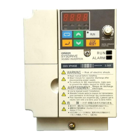
Chapter 1 Overview Nomenclature H Panel Digital Operator Front panel RUN indicator mounting ALARM display screw Terminal cover Front cover Four mounting holes Bottom cover Note None of the following 200-V models have a terminal cover or mounting holes. Instead, the front cover is used as a terminal cover and two U-shaped cutouts are provided in place of the mounting holes. -
Page 28: Digital Operator
Chapter 1 Overview H Digital Operator Data display Simplified-LED FREQUENCY indicators adjuster Operation keys Appearance Name Function Data display Displays relevant data items, such as frequency reference, output frequency, and parameter set values. FREQUENCY adjuster Sets the frequency reference within a range between 0 Hz and the maximum frequency. - Page 29 Chapter 1 Overview Appearance Name Function Decrement Key Decreases multi-function monitor numbers, parameter numbers, and parameter set values. Enter Key Enters multi-function monitor numbers, parameter numbers, and internal data values after they are set or changed. RUN Key Starts the Inverter running when the 3G3MV is in operation with the Digital Operator.
-
Page 30: New Features
Chapter 1 Overview New Features New features have been added to 3G3MV-Series models with 5.5-kW and 7.5-kW ca- pacities (i.e., the 3G3MV-A2055/A2075/ A4055/A4075). These features are outlined below and explained in detail in Chapter 6. H New Features for 3G3MV-A2055/A2075/A4055/A4075 Only D Enclosure Rating: Closed Wall-mounting Conforming to IP20/NEMA1 The 5.5-kW and 7.5-kW Inverters have closed wall-mounting specifications that conform to IP20/NEMA1, so they can operate in an ambient temperature range of –10 to 40°C. - Page 31 Chapter 1 Overview D Output Open-phase Detection (Parameters: n168, n169; Fault Display: LF) This function detects open phases between the Inverter output and the motor. D Ground Fault Detection (Fault Display: GF) This function detects ground faults between the Inverter output and the motor. D Load Short-circuit Detection (Fault Display: SC) Prior to an Inverter output, this function detects whether the output is short-circuited.
-
Page 33: Chapter 2. Design
Chapter 2 Design Installation Wiring... -
Page 34: Installation
Chapter 2 Design Installation 2-1-1 Dimensions D 3G3MV-A2001 to 3G3MV-A2007 (0.1 to 0.75 kW) 3-phase 200-V AC Input 3G3MV-AB001 to 3G3MV-AB004 (0.1 to 0.4 kW) Single-phase 200-V AC Input Dimensions (mm) Rated voltage Model 3G3MV- Weight (kg) ( g) 3-phase 200 V AC A2001 Approx. - Page 35 Chapter 2 Design D 3G3MV-A2015 to 3G3MV-A2022 (1.5 to 2.2 kW) 3-phase 200-V AC Input 3G3MV-AB007 to 3G3MV-AB015 (0.75 to 1.5 kW) Single-phase 200-V AC Input 3G3MV-A4002 to 3G3MV-A4022 (0.2 to 2.2 kW) 3-phase 400-V AC Input Four, 5 dia. Dimensions (mm) Rated voltage Model 3G3MV-...
- Page 36 Chapter 2 Design D 3G3MV-A2037 (3.7 kW) 3-phase 200-V AC Input 3G3MV-AB022 (2.2 kW) Single-phase 200-V AC Input 3G3MV-A4037 (3.7 kW) 3-phase 400-V AC Input Four, 5 dia. Dimensions (mm) Rated voltage Model 3G3MV- Weight (kg) ( g) 3-phase 200 V AC A2037 Approx.
- Page 37 Chapter 2 Design D 3G3MV-A2055 to -A2075 (5.5 to 7.5 kW) 3-phase 200-V AC Input 3G3MV-A4055 to -A4075 (5.5 kW to 7.5 kW) 3-phase 400-V AC Input Two, 6 dia. Dimensions (mm) Rated voltage Model 3G3MV- Weight (kg) ( g) 3-phase 200 V AC A2055 Approx.
-
Page 38: Installation Conditions
Chapter 2 Design 2-1-2 Installation Conditions H Installation Precautions WARNING Provide an appropriate stopping device on the machine side to secure safety. (A holding brake is not a stopping device for securing safety.) Not doing so may result in injury. WARNING Provide an external emergency stopping device that allows an instantaneous stop of operation and power interruption. - Page 39 Chapter 2 Design H Direction • Install the Inverter on a vertical surface so that the characters on the nameplate are oriented upward. H Dimensions • When installing the Inverter, always provide the following clearances to allow normal heat dissipation from the Inverter.
-
Page 40: Removing And Mounting The Covers
Chapter 2 Design 2-1-3 Removing and Mounting the Covers To mount the Inverter, it is necessary to remove the front cover, terminal cover (unless the Inverter is a 200-V model), and the Digital Operator. To wire the Inverter, it is neces- sary to remove the front cover, terminal cover (unless the Inverter is a 200-V model), and bottom cover from the Inverter. -
Page 41: Removing The Terminal Cover
Chapter 2 Design H Removing the Terminal Cover D 0.2- to 3.7-kW Inverters • After the front cover is removed, press the left and right sides of the terminal cover in the arrow 1 direc- tions and lift the terminal cover in the arrow 2 direction as shown in the following illustration. D 5.5-/7.5-kW Inverters •... -
Page 42: Removing The Bottom Cover
Chapter 2 Design H Removing the Bottom Cover D 0.2- to 3.7-kW Inverters • After removing the front cover and terminal cover, press the bottom cover in the arrow 1 direction based on position A as a fulcrum. D 5.5-/7.5-kW Inverters •... -
Page 43: Wiring
Chapter 2 Design Wiring WARNING Wiring must be performed only after confirming that the power supply has been turned OFF. Not doing so may result in electrical shock. WARNING Wiring must be performed by authorized personnel. Not doing so may result in electrical shock or fire. -
Page 44: Terminal Block
Chapter 2 Design 2-2-1 Terminal Block To wire the terminal block of the Inverter, remove the front cover, terminal cover (unless the Inverter is a low-capacity 200-V model), and bottom cover from the Inverter. There is a label under the front cover indicating the arrangement of main circuit termi- nals. - Page 45 Chapter 2 Design D 3G3MV-A2015 to 3G3MV-A2022 (1.5 to 2.2 kW): 3-phase 200-V AC Input 3G3MV-AB007 to 3G3MV-AB015 (0.75 to 1.5 kW): Single-phase 200-V AC Input 3G3MV-A4002 to 3G3MV-A4022 (0.2 to 2.2 kW): 3-phase 400-V AC Input Braking Power supply input Motor output Resistor Note For single-phase input, connect R/L1 and S/L2.
-
Page 46: Main Circuit Terminals
Chapter 2 Design H Main Circuit Terminals Symbol Name Description Power supply input pp y R/L1 3G3MV-A2j: 3-phase 200 to 230 V AC terminals S/L2 3G3MV-ABj: Single-phase 200 to 240 V AC (See note 1.) T/L3 3G3MV-A4j: 3-phase 380 to 460 V AC Motor output terminals 3-phase power supply output for driving motors. -
Page 47: Control Circuit Terminals
Chapter 2 Design H Control Circuit Terminals Symbol Name Specification Input Multi-function input 1 (For- Photocoupler ward/Stop) 8 mA at 24 V DC (See notes 2 and 3.) C (S Multi-function input 2 (Reverse/Stop) Multi-function input 3 (External fault: Normally open) Multi-function input 4 (Fault reset) - Page 48 Chapter 2 Design Symbol Name Specification Out- Multi-function contact out- Relay output 1 A max. at 30 V DC put (Normally open: Fault) 1 A max. at 250 V AC Multi-function contact out- put (Normally closed: Fault) Multi-function contact out- put common Multi-function photocoupler Open collector output 50 mA max.
- Page 49 Chapter 2 Design Note 4. When multi-function analog outputs are used for pulse train outputs, they can be directly con- nected to the pulse train inputs at other 3G3MV-series Inverters for simple synchronization or other applications. H Selecting Input Method •...
- Page 50 Chapter 2 Design D Selecting RS-422/485 Termination Resistance • Termination resistance can be selected by setting pin 1 of the SW2 to ON. The default setting for the pin is OFF. Selects RS-422/485 termination resistance Selects frequency reference input method Communications method Pin 1 setting RS-422...
- Page 51 Chapter 2 Design D Frequency Reference Input by PLC Pulse Train ON when 3.5 V or higher OFF when 0.8 V or lower Note Use twisted pair shielded wire no longer than 5 m for pulse train input lines in order to suppress noise.
-
Page 52: Standard Connections
Chapter 2 Design 2-2-2 Standard Connections DC reactor Braking Resistor (optional) (optional) Noise Filter 3-phase 200/400 V AC Single-phase 200 V AC (See note.) Multi-function contact output Multi-function input 1 Multi-function input 2 Multi-function input 3 Common Multi-function input 4 Multi-function input 5 Multi-function photocoupler output 1... -
Page 53: Wiring Around The Main Circuit
Chapter 2 Design D Example of 3-wire Sequence Connections Stop switch switch (NO) (NC) RUN input (Operates with the RUN switch and Stop switch closed) Stop input (Stops with the Stop switch opened) Direction switch Forward/Reverse rotation command input. (Forward with the Direction switch opened. - Page 54 Chapter 2 Design Model Terminal symbol Terminal Screw Wire size Recom- Molded- 3G3MV- screw tightening mended case cir- torque wire size cuit (NSm) breaker capacity A2037 1.2 to 1.5 2 to 5.5 R/L1, S/L2, T/L3, B1, B2, –, +1, +2, U/T1, V/T2, W/T3 A2055 R/L1, S/L2, T/L3, B1, B2, –, 5.5 to 8...
- Page 55 Chapter 2 Design D 3-phase 400-V AC Model Model Terminal symbol Terminal Screw Wire size Recom- Molded- 3G3MV- screw tightening mended case cir- torque wire size cuit (NSm) breaker capacity A4002 R/L1, S/L2, T/L3, B1, B2, –, 1.2 to 1.5 2 to 5.5 +1, +2, U/T1, V/T2, W/T3 A4004...
- Page 56 Chapter 2 Design H Wiring on the Input Side of the Main Circuit D Installing a Molded-case Circuit Breaker Always connect the power input terminals (R/L1, S/L2, and T/L3) and power supply via a molded case circuit breaker (MCCB) suitable to the Inverter. •...
- Page 57 Chapter 2 Design D Installing a Magnetic Contactor If the power supply of the main circuit is to be shut off because of the sequence, a magnetic contactor can be used instead of a molded-case circuit breaker. When a magnetic contactor is installed on the primary side of the main circuit to stop a load forcibly, however, the regenerative braking does not work and the load coasts to a stop.
- Page 58 Chapter 2 Design D Installing a Noise Filter on the Power Supply Side The Inverter’s outputs utilize high-speed switching, so noise may be transmitted from the Inverter to the power line and adversely affect other devices in the vicinity. It is recommended that a Noise Filter be installed at the Power Supply to minimize this noise transmission.
- Page 59 Chapter 2 Design D Installing a Thermal Relay The Inverter has an electronic thermal protection function to protect the motor from overheating. If, how- ever, more than one motor is operated with one inverter or a multi-polar motor is used, always install a thermal relay (THR) between the Inverter and the motor and set n037 to 2 (no thermal protection).
- Page 60 Chapter 2 Design D Countermeasures against Radio Interference Radio noise is generated from the Inverter as well as the input and output lines. To reduce radio noise, install Noise Filters on both input and output sides, and also install the Inverter in a totally enclosed steel box.
-
Page 61: Ground Wiring
Chapter 2 Design H Ground Wiring • Always use the ground terminal of the 200-V Inverter with a ground resistance of 100 Ω or less. Simi- larly, always use the ground terminal of the 400-V Inverter with a ground resistance of 10 Ω or less. •... - Page 62 Chapter 2 Design The following frequencies are harmonics of a 60- or 50-Hz commercial power supply. Second harmonic: 120 (100) Hz Third harmonic: 180 (150) Hz Second harmonic (120 Hz) Basic frequency (60 Hz) Third harmonic (180 Hz) Problems Caused by Harmonics Generation The waveform of the commercial power supply will be distorted if the commercial power supply contains excessive harmonics.
- Page 63 Chapter 2 Design Inverter The Inverter as well as normal electric machines has an input current containing harmonics because the Inverter converts AC into DC. The output current of the Inverter is comparatively high. Therefore, the ratio of harmonics in the output current of the Inverter is higher than that of any other electric machine. Voltage Time Rectified...
- Page 64 Chapter 2 Design D Countermeasures with Reactors against Harmonics Generation DC/AC Reactors The DC reactor and AC reactor suppress harmonics and currents that change suddenly and greatly. The DC reactor suppresses harmonics better than the AC reactor. The DC reactor used with the AC reactor suppresses harmonics more effectively.
- Page 65 Chapter 2 Design Reactor Effects Harmonics are effectively suppressed when the DC reactor is used with the AC reactor as shown in the following table. Harmonic generation rate (%) Harmonics suppression 5th har- 7th har- 11th har- 13th har- 17th har- 19th har- 23rd 25th...
-
Page 66: Wiring Control Circuit Terminals
Chapter 2 Design D Braking Resistors and Braking Resistor Units for 200-V-class Inverters Inverter Braking Resistor Braking Resistor Unit Minimum 3G3MV- (3% usage rate ED) (10% usage rate ED) connection 3G3IV- 3G3IV- resistance PERF150WJ401 (400 Ω) 300 Ω A2001/AB001 A2002/AB002 PERF150WJ201 (200 Ω) PLKEB20P7 (200 Ω, 70 W) 200 Ω... - Page 67 Chapter 2 Design D Wires and Tightening Torque Multi-function Contact Output (MA, MB, and MC) Terminal Tightening Wire Wire size mm Recommended Cable screw size torque (AWG) wire size mm N S m (AWG) 0.5 to 0.6 Single wire 0.5 to 1.25 (20 to 16) 0.75 (18) Cable with polyethylene polyethylene...
-
Page 68: Conforming To Ec Directives
Chapter 2 Design Note 1. Always separate the control signal line from the main circuit cables and other power cables. Note 2. Do not solder the wires to the control circuit terminals. The wires may not contact well with the control circuit terminals if the wires are soldered. - Page 69 Chapter 2 Design D Control Circuit Terminals Multi-function contact output Multi-function input 1 Multi-function input 2 Common Multi-function input 3 Multi-function input 4 Multi-function photocoupler output 1 Multi-function input 5 Multi-function input 6 Multi-function input 7 Multi-function photocoupler output 2 Sequence input common Frequency reference power Multi-function photocoupler...
- Page 70 Chapter 2 Design H Conforming to EC Directives D Wiring the Power Supply Make sure that the Inverter and Noise Filter are grounded together. • Always connect the power input terminals (R/L1, S/L2, and T/L3) and power supply via a dedicated Noise Filter.
- Page 71 Chapter 2 Design D Wiring a Control Cable • Be sure to connect a cable with a braided shield to the control circuit terminals. • Ground the shield on the Inverter side only. D Grounding the Shield In order to ground the shield securely, it is recommended that a cable clamp be directly connected to the ground plate as shown below.
- Page 72 Chapter 2 Design • Wireless devices and other equipment that generates electromagnetic waves should never be installed in the same control panel with the Inverter. • The DC power supply used for communications should have reinforced or double insulation. • An Inverter control terminal has only basic insulation.
- Page 73 Chapter 2 Design Note To satisfy LVD requirements, the Inverter must be protected with a line breaker in case a short-cir- cuiting accident occurs. When using a single line breaker to be shared with other Inverters or devices, make sure that the Inverters and devices will be fully protected if there is a one-point short-circuit, otherwise the Inverters and devices may be damaged.
-
Page 75: Chapter 3. Preparing For Operation And Monitoring
Chapter 3 Preparing for Operation and Monitoring Nomenclature Parameter Copy and Verify Function... -
Page 76: Nomenclature
Preparing for Operation and Monitoring Chapter 3 Nomenclature 3-1-1 Names of Parts and their Functions Data display Simplified-LED FREQUENCY indicators adjuster Operation keys Appearance Name Function Data display Displays relevant data items, such as frequency reference, output frequency, and parameter set values. FREQ adjuster Sets the frequency reference within a range between 0 Hz and the maximum frequency. - Page 77 Preparing for Operation and Monitoring Chapter 3 Appearance Name Function Mode Key Switches the simplified-LED (setting and monitor) item indicators in sequence. Parameter setting being made is canceled if this key is pressed before entering the setting. Increment Key Increases multi-function monitor numbers, parameter numbers, and parameter set values.
-
Page 78: Outline Of Operation
Preparing for Operation and Monitoring Chapter 3 3-1-2 Outline of Operation H Selecting Indicators Whenever the Mode Key is pressed, an indicator is lit in sequence beginning with the FREF indicator. The data display indicates the item corresponding to the indicator selected. - Page 79 Preparing for Operation and Monitoring Chapter 3 H Example of Frequency Reference Settings Key sequence Indicator Display Explanation example Power On Note If the FREF indicator has not been lit, press the Mode Key repeatedly until the FREF indicator is lit. Use the Increment or Decrement Key to set the frequency reference.
- Page 80 Note “1” means that the latest error is displayed. Press the Increment Key to display the second latest error. A maxi- mum of four errors can be displayed. U-10 Software No. OMRON use only. U-11 Output power Monitors the output power of the Inverter. (See note 2.) U-13...
- Page 81 Preparing for Operation and Monitoring Chapter 3 Item Display Display Function unit U-15 Communications Displays communications errors that occur during serial error communications (RS-422/RS-485). The errors that are displayed have the same content as the serial communications error at register number 003D Hex. : Error : Normal operation...
- Page 82 Preparing for Operation and Monitoring Chapter 3 H Example of Local/Remote Selection Settings Key sequence Indicator Display Explanation example Press the Mode Key repeatedly until the LO/RE indicator is lit. The present setting will be displayed. rE: Remote; Lo: Local Use the Increment or Decrement Key to set the Inverter to local or remote mode.
- Page 83 Preparing for Operation and Monitoring Chapter 3 Note 1. To cancel the set value, press the Mode Key instead. The parameter number will be dis- played. Note 2. There are parameters that cannot be changed while the Inverter is in operation. Refer to the list of parameters.
-
Page 84: Parameter Copy And Verify Function
Preparing for Operation and Monitoring Chapter 3 Parameter Copy and Verify Function The Digital Operator of the 3G3MV Inverter has an EEPROM in which the set values in all the parameters and data on the capacity and software version of the Inverter can be stored. -
Page 85: Parameter Copying Procedure
Preparing for Operation and Monitoring Chapter 3 H Sequence of Display Completed Reading reading Completed Writing writing Completed Verifying verifying Inverter capacity Software version Note The following display is an example of the capacity displayed. The values in parentheses indicate the capacities for European motors. - Page 86 Preparing for Operation and Monitoring Chapter 3 7. Check that the data is written correctly with the item vFy selected. • The above procedure is possible provided that the Inverters have the same power supply specification and control mode (i.e., V/f or vector control). It is not possible to copy parameters from a 200-V model to a 400-V model or from an Inverter that is in V/f control mode to another that is in vector control mode, for example.
- Page 87 Preparing for Operation and Monitoring Chapter 3 Parame- Register Name Description Setting Unit of Default Chan- range setting setting ges dur- opera- tion n001 0101 Parame- Used to prohibit parameters 0 to 11 ter write- to be written, sets parame- prohibit ters, or change the monitor selec-...
- Page 88 Preparing for Operation and Monitoring Chapter 3 D Parameter Settings in n001 Key sequence Indicator Display Explanation example Power ON Press the Mode Key repeatedly until the PRGM indicator is lit. Check that “n001” is displayed. Press the Enter Key. The data of the specified parameter number is displayed.
- Page 89 Preparing for Operation and Monitoring Chapter 3 H Copying the Data in the EEPROM of the Digital Operator to another Inverter (CPy) • To copy the parameter set values to another Inverter from the EEPROM of the Digital Operator, set n176 for parameter copy function selection to CPy.
- Page 90 Preparing for Operation and Monitoring Chapter 3 Note 3. The following parameter set values cannot be copied if the Inverters are different to each other in capacity. n011 to n017: V/f setting n108: Motor leakage inductance n036: Rated motor current n109: Torque compensation limit n080: Carrier frequency n110: Motor no-load current...
-
Page 91: Parameter Read-Prohibit Selection
Preparing for Operation and Monitoring Chapter 3 Note 2. By attempting to verify the parameter set values in Inverters that are different in capacity, “vAE” flashes for a capacity error. Press the Enter Key to continue verifying the parameter set values. -
Page 92: Parameter Copy Or Verify Errors
Preparing for Operation and Monitoring Chapter 3 Key sequence Indicator Display Explanation example Press the Enter Key so that the set value will be entered and the data display will be lit. In approximately The parameter number will be displayed again in 1 s. -
Page 93: Chapter 4. Test Run
Chapter 4 Test Run Procedure for Test Run Operation Example... - Page 94 Chapter 4 Test Run WARNING Turn ON the input power supply only after mounting the front cover, terminal covers, bottom cover, Operator, and optional items. Not doing so may result in electrical shock. WARNING Do not remove the front cover, terminal covers, bottom cover, Operator, or optional items while the power is being supplied.
-
Page 95: Procedure For Test Run
Chapter 4 Test Run Procedure for Test Run 1. Installation and Mounting Install the Inverter according to the installation conditions. Refer to page 2-2. Ensure that the instal- lation conditions are met. 2. Wiring and Connection Connect to the power supply and peripheral devices. Refer to page 2-11. Select peripheral devices which meet the specifications and wire correctly. - Page 96 Chapter 4 Test Run 7. No-load Operation Start the no-load motor using the Digital Operator. S Set the frequency reference using the Digital Operator and start the motor using key sequences. 8. Actual Load Operation Connect the mechanical system and operate using the Digital Operator. S When there are no difficulties using the no-load operation, connect the mechanical system to the motor and operate using the Digital Operator.
-
Page 97: Operation Example
Chapter 4 Test Run Operation Example Power Connection H Checkpoints before Connecting the Power Supply • Check that the power supply is of the correct voltage and that the motor output terminals (R/L1, S/L2, and T/L3) are connected to the motor correctly. 3G3MV-A2j: Three-phase 200 to 230 V AC 3G3MV-ABj: Single-phase 200 to 240 V AC (Wire R/L1 and S/L2) 3G3MV-A4j: Three-phase 380 to 460 V AC... -
Page 98: Test Run
Chapter 4 Test Run Initializing Parameters • Initialize the parameters using the following procedure. • To initialize the parameters, set n01 to 8. Key sequence Indicator Display Explanation example Power On Press the Mode Key repeatedly until the PRGM indicator is lit. - Page 99 Chapter 4 Test Run Key sequence Indicator Display Explanation example The parameter number is displayed. Use the Increment or Decrement Key to display “n002.” Press the Enter Key to display the set value in n002. Use the Increment or Decrement key to set n002 to 0 unless the value is already set to 0, during which the display flashes.
-
Page 100: Actual Load Operation
Chapter 4 Test Run No-load Operation • Start the no-load motor (i.e., not connected to the mechanical system) using the Digital Operator. Note Before operating the Digital Operator, check that the FREQ adjuster is set to MIN. H Forward/Reverse Rotation with the Digital Operator Indicator Display Explanation... - Page 101 Chapter 4 Test Run H Checking the Operating Status • Having checked that the operating direction is correct and that the machine is operating smoothly at slow speed, increase the frequency reference. • After changing the frequency reference or the rotation direction, check that there is no vibration or abnormal sound from the motor.
-
Page 103: Chapter 5. Basic Operation
Chapter 5 Basic Operation Initial Settings Operation in Vector Control Operation in V/f Control Setting the Local/Remote Mode Selecting the Operation Command Setting the Frequency Reference Setting the Acceleration/Deceleration Time Selecting the Reverse Rotation-prohibit Selecting the Stopping Method 5-10 Multi-function I/O 5-11 Multi-function Analog Output and Pulse Monitor Output... -
Page 104: Initial Settings
Chapter 5 Basic Operation This section explains the basic settings required to operate and stop the Inverter. The settings of parameters described here will be sufficient for simple Inverter opera- tions. First make these basic settings and then skip to the explanations of those special func- tions, even when your application requires special functions, such as energy-saving control, PID control, stall prevention, carrier frequency setting, overtorque detection, torque compensation, slip compensation. -
Page 105: Setting The Control Mode (N002)
Chapter 5 Basic Operation delay time constant), n111 (slip compensation gain), n112 (slip compensation primary-delay time constant) 5-1-2 Setting the Control Mode (n002) • The 3G3MV Inverter operates in vector or V/f control mode to be selected according to the application. •... -
Page 106: Basic Operation
Chapter 5 Basic Operation Default value Parameter Name V/f control Vector control (Set value: 0) (Set value: 1) n014 Middle output frequency 1.5 Hz 3.0 Hz n015 Middle output frequency voltage 12.0 V (24.0 V) 11.0 V (22.0 V) (See note 2.) n016 Minimum output frequency 1.5 Hz... -
Page 107: Operation In Vector Control
Chapter 5 Basic Operation Operation in Vector Control The Inverter in vector control mode calculates the vector of the operating condition of the motor. Then the 150% rated output torque of the motor is provided at an output fre- quency of 1 Hz. Vector control provides more powerful motor control than V/f control and makes it possible to suppress speed fluctuation with changes in loads. - Page 108 Chapter 5 Basic Operation Note 1. The value will be set in 0.001-Ω increments if the resistance is less than 10 Ω and 0.01-Ω increments if the resistance is 10 Ω or over. Note 2. The default setting for this parameter is the standard phase-to-neutral resistance of the maxi- mum applicable motor.
-
Page 109: Operation In V/F Control
Chapter 5 Basic Operation Operation in V/f Control This mode, which is used by conventional general-purpose inverters, is convenient when replacing a conventional model with the 3G3MV Inverter because the Inverter in this mode can be operated without considering the constants of the motor. Furthermore, set the Inverter to this mode if the Inverter is connected to two or more motors or special motors, such as high-speed motors. - Page 110 Chapter 5 Basic Operation n015 Middle Output Frequency Voltage Register 010F Hex Changes during (VC) operation Setting 0.1 to 255.0 [0.1 to 510.0] (V) Unit of 0.1 V Default setting 12.0 range setting [24.0] (See note 2.) n016 Minimum Output Frequency Register 0110 Hex Changes during...
-
Page 111: Setting The Local/Remote Mode
Chapter 5 Basic Operation Setting the Local/Remote Mode The 3G3MV operates in local or remote mode. The following description provides information on these modes and how to select them. H Basic Concept Operation mode Basic concept Description Remote The Inverter in a system Operation Command operates according to the Selectable from four types and set in n003. -
Page 112: Selecting The Operation Command
Chapter 5 Basic Operation Selecting the Operation Command The following description provides information on how to input operation commands to start or stop the Inverter or change the direction of rotation of the Inverter. Two types of command input methods are available. Select either one of them according to the application. -
Page 113: Setting The Frequency Reference
Chapter 5 Basic Operation Setting the Frequency Reference 5-6-1 Selecting the Frequency Reference The following description provides information on how to set the frequency reference in the Inverter. Select the method according to the operation mode. Remote mode: Select and set one out of ten frequency references in n004. Local mode: Select and set one out of two frequency references in n008. -
Page 114: Upper And Lower Frequency Reference Limits
Chapter 5 Basic Operation Note 4. Set n149 for the pulse train input scale to the pulse train frequency that is equivalent to the maximum frequency (FMAX). • The frequency reference set in n004 functions as frequency reference 1 when the Inverter is in multi- step speed operation. -
Page 115: Frequency Referencing By Analog Input
Chapter 5 Basic Operation 5-6-3 Frequency Referencing by Analog Input This section explains the methods for referencing frequencies by analog input, adjusting input characteristics, and detecting input command errors. Either the frequency refer- ence control terminal (voltage/current) or multi-function analog voltage/current input can be used for analog inputs. - Page 116 Chapter 5 Basic Operation D Filter Time Constant Settings (n062) • A primary-delay digital filter can be set for analog frequency references to be input. • This setting is ideal if the analog input signal changes rapidly or the signal is subject to noise interfer- ence.
- Page 117 Chapter 5 Basic Operation • For n077, select from the following five functions allocated to the multi-function analog input terminal. n077 Set Values Value Name Description Multi-function Disables multi-function analog inputs. Analog Input Set 0 when setting multi-function inputs with n004 (Frequency Reference Function Disable Selection) or n164 (PID Feedback Input Block Selection).
- Page 118 Chapter 5 Basic Operation H Adjusting Multi-function Analog Input D Setting the Gain and Bias of Multi-function Analog Voltage/Current Input (n068 to n072) • Set the multi-function analog voltage input characteristics in n068 (multi-function analog voltage input gain) and n069 (multi-function analog voltage input bias). Set the multi-function analog current input characteristics in n071 (multi-function analog current input gain) and n072 (multi-function analog cur- rent input bias).
- Page 119 Chapter 5 Basic Operation D Setting the Filter Time Constant for Multi-function Analog Voltage/Current Input (n070 and n073) • These parameters can be used to set a primary-delay digital filter for multi-function analog voltage input. For voltage inputs, set the multi-function analog voltage input filter time constant (n070). For current inputs, set the multi-function analog current input filter time constant (n073).
-
Page 120: Setting Frequency References Through Key Sequences
Chapter 5 Basic Operation 5-6-4 Setting Frequency References through Key Sequences The following description provides information on parameters related to frequency ref- erence settings through key sequences on the Digital Operator H Frequency Reference Setting/Display Unit Selection (n035) • Set the unit of frequency reference and frequency-related values to be set or monitored in n035 through the Digital Operator. - Page 121 Chapter 5 Basic Operation H Setting Frequency References 1 through 16 and the Inching Frequency Command (n024 through n031, n120 through n127) Frequency references 1 through 16 and an inching frequency command can be set together in the Inverter (using registers n024 through n31, n120 through n127). D Setting Frequency References 1 through 16 (n024 through n31, n120 through n127) n024 Frequency Reference 1...
- Page 122 Chapter 5 Basic Operation n120 Frequency Reference 9 Register 0178 Hex Changes during operation Setting 0.00 to max. frequency Unit of 0.01 Hz Default setting 0.00 range setting (See note n121 Frequency Reference 10 Register 0179 Hex Changes during operation Setting 0.00 to max.
- Page 123 Chapter 5 Basic Operation relationship between multi-step speed references 1 through 4 and frequency references 1 through 16. Frequency reference Multi-step speed Multi-step speed Multi-step speed Multi-step speed reference 1 reference 2 reference 3 reference 4 (Set value: 6) (Set value: 7) (Set value: 8) (Set value: 9) Frequency reference 1...
- Page 124 Chapter 5 Basic Operation H Setting the Frequency Reference with the FREF Indicator Lit • The frequency reference can be set while the FREF indicator of the Digital Operator is lit in the follow- ing cases. S Parameter n004 for frequency reference selection is set to 1, which enables frequency reference 1, and the Inverter is in remote mode.
-
Page 125: Setting Frequency References By Pulse Train Input
Chapter 5 Basic Operation 5-6-5 Setting Frequency References by Pulse Train Input By setting n004 for frequency reference selection to 5 for enabling the pulse train refer- ence control terminal, frequency references can be executed by pulse train input through the PR terminal. The following description provides information on the n149 parameter (pulse train input scale), which is used to execute frequency references by pulse train input. - Page 126 Chapter 5 Basic Operation n075 Pulse Train Frequency Reference Register 014B Hex Changes during Bias operation Setting –100 to 100 Unit of Default setting range setting Frequency reference (Hz) Pulse train input frequency (Hz) n011: Maximum frequency H Pulse Train Frequency Reference Input Filter Constant (n076) •...
-
Page 127: Setting The Acceleration/Deceleration Time
Chapter 5 Basic Operation Setting the Acceleration/Deceleration Time The following description provides information on parameters related to acceleration and deceleration time settings. Trapezoidal and S-shape acceleration and deceleration are available. Using the S-shape characteristic function for acceleration and deceleration can reduce shock to the machinery when stopping or starting. - Page 128 Chapter 5 Basic Operation • If acceleration/deceleration time selection 2 (setting: 27) is not set at any multi-function input from n050 to n056, the Inverter will determine that the acceleration/deceleration selection 2 is set to OFF, and select the acceleration/deceleration time. In the same way, if acceleration/deceleration time selection 1 (setting: 11) is not set at any multi-func- tion input, the Inverter will determine that the acceleration/deceleration selection 1 is set to OFF, and select the acceleration/deceleration time.
- Page 129 Chapter 5 Basic Operation Note 1. The setting unit of acceleration or deceleration time is determined by the set value in n018 (acceleration/deceleration time setting unit). n018 set to 0 (0.1 s unit): Setting range from 0.0 to 6,000 s (0.0 to 999.9 s or 1,000 to 6,000 s) n018 set to 1 (0.01 s unit): Setting range from 0.00 to 600.0 s (0.0 to 99.99 s or 100.0 to 600.0 s) Note 2.
-
Page 130: Selecting The Reverse Rotation-Prohibit
Chapter 5 Basic Operation Selecting the Reverse Rotation-prohibit This parameter is used to specify whether to enable or disable the reverse rotation com- mand sent to the Inverter from the control circuit terminals or Digital Operator. The parameter should be set to “not accept” when the Inverter is applied to systems that prohibit the reverse rotation of the Inverter. -
Page 131: Selecting The Stopping Method
Chapter 5 Basic Operation Selecting the Stopping Method This parameter is used to specify the stopping method when the STOP command is input. The Inverter either decelerates or coasts to a stop according to the stopping method selection. H Selecting the Stopping Method (n005) n005 Stopping Method Selection Register... -
Page 132: Multi-Function I/O
Chapter 5 Basic Operation 5-10 Multi-function I/O 5-10-1 Multi-function Input The 3G3MV incorporates seven multi-function input terminals (S1 through S7). Inputs into these terminals have a variety of functions according to the application. H Multi-function Input (n050 through n056) n050 Multi-function Input 1 (S1) Register 0132 Hex... - Page 133 Chapter 5 Basic Operation Set Values Value Function Description Forward/Reverse rotation 3-wire sequence (to be set in n052 only) command By setting n052 to 0, the set values in n050 and n051 are ignored and the following settings are forcibly made. S1: RUN input (RUN when ON) S2: STOP input (STOP when OFF) S3: Forward/Reverse rotation command...
- Page 134 Chapter 5 Basic Operation Value Function Description Emergency stop fault The Inverter stops according to the setting in n005 for interruption mode selection with the emergency stop input turned ON. (NO) n005 set to 0: Decelerates to stop at deceleration time 2 set in n005 set to 0: Decelerates to stop at deceleration time 2 set in Emergency stop warning n022.
- Page 135 Chapter 5 Basic Operation Value Function Description General -purpose input 1 The Inverter will not operate with S1 to S7 sensor input if these functions are set. They are used when you want sensors to provide t Th General -purpose input 2 SYSMAC information via the Inverter for RS422/485 or Option Unit SYSMAC information via the Inverter for RS422/485 or Option Unit General -purpose input 3...
- Page 136 Chapter 5 Basic Operation H Operation in 3-wire Sequence (n052 = 0) • The Inverter operates in 3-wire sequence by setting n052 for multi-function input 3 to 0. • Only n052 can be set to 0 (3-wire sequence). By making this setting, the set values in n050 and n051 are ignored and the following settings are forcibly made.
- Page 137 Chapter 5 Basic Operation H Speed Search (Set Value: 14, 15) • The speed search function is provided for smooth restarting without stopping a free running motor. Use it when switching the motor from a commercial power supply operation to Inverter operation, when starting with the Inverter a motor turned by external force, and so on.
-
Page 138: Multi-Function Output
Chapter 5 Basic Operation • For n101, set the origin search deceleration time to the time required to go from 100% to 0% of the maximum frequency. • If 0 is set for the origin search deceleration time, operation will be carried out at the default setting of 2.0 seconds. - Page 139 Chapter 5 Basic Operation Value Function Description Undertorque being Output if any of the following parameter conditions is satisfied. monitored (NO-contact • Undertorque detection function selection (n117) output) • Undertorque detection level (n118) • Overtorque detection function selection 2 (n097) 2 ( 097) Undertorque being •...
-
Page 140: Multi-Function Analog Output And Pulse Monitor Output
Chapter 5 Basic Operation 5-11 Multi-function Analog Output and Pulse Monitor Output The 3G3MV Inverter incorporates multi-function analog output terminals (AM and AC). A parameter setting makes it possible to output pulse monitor signals from these termi- nals. Make the necessary settings in these terminals according to the application. 5-11-1 Setting the Multi-function Analog Output (n065 through n067) •... -
Page 141: Setting The Pulse Monitor Output (N065 And N150)
Chapter 5 Basic Operation Note 1. Refer to the above information on the set values in n066 and set the multiplication rate based on the reference value. For example, if 5-V output is desired at maximum output frequency (with n066 set to 0), set n067 to 0.50. Note 2. -
Page 143: Chapter 6. Advanced Operation
Chapter 6 Advanced Operation Precise Vector Control Settings and Adjustments Energy-saving Control PID Control Setting the Carrier Frequency DC Injection Braking Function Stall Prevention Function Overtorque/Undertorque Detection Function Torque Compensation Function Slip Compensation Function 6-10 Other Functions... -
Page 144: Precise Vector Control Settings And Adjustments
Chapter 6 Advanced Operation This chapter provides information on the use of advanced functions of the Inverter for operation. Refer to this chapter to use the various advanced functions, such as precise vector con- trol setting, energy-saving control, PID control, carrier frequency setting, DC injection braking, stall prevention, overtorque detection, torque compensation, and slip com- pensation. -
Page 145: Adjusting Output Torque In Vector Control
Chapter 6 Advanced Operation Note 1. The value will be set in 0.01-mH increments if the resistance is less than 100 mH and 0.1-mH increments if the resistance is 100 mH or over. Note 2. The default setting for this parameter is the standard leakage inductance of the maximum applicable motor. - Page 146 Chapter 6 Advanced Operation n012 Maximum Voltage (VMAX) Register 010C Hex Changes during operation Setting 0.1 to 255.0 (0.1 to 510.0) (V) Unit of 0.1 V Default setting 200.0 range setting (400.0) n013 Maximum Voltage Frequency (FA) Register 010D Hex Changes during operation Setting...
-
Page 147: Energy-Saving Control
Chapter 6 Advanced Operation Energy-saving Control The energy-saving control function automatically saves unnecessary power that is use- lessly consumed while the load is light. The Inverter in energy-saving control estimates the capacity of the load from the motor current and controls the output voltage of the Inverter when the load is light so that only the power required is provided to the motor. -
Page 148: Performing Energy-Saving Settings
Chapter 6 Advanced Operation Deceleration The Inverter decelerates normally and is not in energy-saving control. Power consumption As shown in the graph, the voltage to operate the motor most efficiently varies with the motor load condition. The Inverter in Load rate: 100% energy-saving control adjusts the output voltage by using the ideal calculated value so that the actual output power will be... - Page 149 Chapter 6 Advanced Operation Motor code Power supply voltage Motor capacity Energy-saving control coefficient K2 (n140) 200 V AC 0.1 kW 481.7 0.2 kW 356.9 0.4 kW 288.2 0.75 kW 223.7 1.5 kW 169.4 2.2 kW 156.8 3.0 kW 156.8 3.7 kW 122.9 4.0 kW...
- Page 150 Chapter 6 Advanced Operation Set Values • Set n143 to the time required to calculate the average of power used in energy-saving control. Power averaging time (ms) = Set value in n143 x 24 (ms) • Normally, the default setting does not need to be changed. •...
- Page 151 Chapter 6 Advanced Operation Set Values • These parameters prevent the motor from over excitation due to voltage changes during energy-sav- ing control. • Set the upper limit of output voltage in percentage at each frequency based on the rated motor voltage as 100%.
- Page 152 Chapter 6 Advanced Operation Set Values • Set the range of probe operation voltage in percentage based on the rated motor voltage as 100%. • Normally, the default setting does not need to be changed. • If the fluctuation of speed in probe operation is large, decrease the set value. If the response of the Inverter in probe operation is slow, increase the set value.
-
Page 153: Pid Control
Chapter 6 Advanced Operation PID Control The PID control function is a control system that matches a feedback value (i.e., a de- tected value) to the set target value. Proportional control, integral control, and derivative control in combination are available to machinery systems involving redundancy time in control operation. -
Page 154: Pid Control Operation
Chapter 6 Advanced Operation 6-3-2 PID Control Operation • To simply explain the operation of proportional control, integral control, and derivative control, the fol- lowing graph is used to show that the output frequency changes while the deviation (i.e., the difference between the target value and feedback value) is constant. - Page 155 Chapter 6 Advanced Operation • Basic PID Control This is the basic control method. The response will be quick if the target value changes because the deviation derivative value is used. If the target value changes rapidly, however, the control value of the derivative control block will be large.
-
Page 156: Block Diagram Of Pid Control
Chapter 6 Advanced Operation 6-3-4 Block Diagram of PID Control • The following diagram shows the PID control block of the 3G3MV Inverter. Limit Max. frequency: 100% Proportional (P) gain Target Integral (I) upper limit value Integral time (I) Multi-function input Integral hold input PID primary delay time... -
Page 157: Input Selection Of Pid Control Target Value And Detection Value
Chapter 6 Advanced Operation 6-3-5 Input Selection of PID Control Target Value and Detection Value • The target value and detected value (feedback value) of PID control are set according to n004 for fre- quency reference selection, n008 for local mode frequency reference selection, and n164 PID feed- back input block selection as shown in the following diagram. -
Page 158: Pid Control Settings
Chapter 6 Advanced Operation 6-3-6 PID Control Settings n128 PID Control Selection Register 0180 Hex Changes during operation Setting 0 to 8 Unit of Default setting range setting Set Values Description Value PID control Derivative control Addition of Positive or negative method frequency reference characteristics... - Page 159 Chapter 6 Advanced Operation n132 Derivative (D) Time Register 0182 Hex Changes during operation Setting 0.0 to 2.50 (s) Unit of 0.01 s Default setting 0.00 range setting Set Values • While the mechanical load is in actual operation, adjust the values so that the best response will be returned from the load.
- Page 160 Chapter 6 Advanced Operation Set Values Value Description Feedback loss detection disabled Feedback loss detection enabled (Nonfatal error: FbL warning) Feedback loss detection enabled (Fatal error: FbL error) Note 1. Set the method of detecting loss of the feedback as a detected value for PID control. Note 2.
-
Page 161: Pid Adjustments
Chapter 6 Advanced Operation Note 1. The maximum frequency (FMAX) is reached with 10-V input. Note 2. The maximum frequency (FMAX) is reached with 20-mA input. The SW2 on the control PCB must be switches from V to I. Note 3. Set n149 for the pulse train input scale to the pulse train frequency that is equivalent to the maximum frequency (FMAX). - Page 162 Chapter 6 Advanced Operation S Measurement of T Measure the required time (seconds) between the point of intersection of the tangent line and time axis and the point of intersection of the tangent line and set point line. Response Target value Time S PID Parameter The following PID parameters are calculated from the R, L, and T of intersection of the tangent line...
-
Page 163: Pid Fine Tuning
Chapter 6 Advanced Operation 6-3-8 PID Fine Tuning • Refer to the following to tune in PID parameters exactly. • Suppression of Overshooting Set the derivative (D) time to a smaller value and the integral (I) time to a larger value if overshooting results. - Page 164 Chapter 6 Advanced Operation • Suppression of Short-cycle Vibration Vibration with a wavelength almost as long as the differential time results from excessive derivative (D) control. The vibration can be suppressed by setting the derivative (D) time to a smaller value. If the vibration cannot be suppressed after the differential time is set to 0.00, set the proportional gain to a smaller value or the PID primary delay time constant to a larger value.
-
Page 165: Setting The Carrier Frequency
Chapter 6 Advanced Operation Setting the Carrier Frequency The carrier frequency of the 3G3MV can be fixed or varied in proportion to the output frequency. n080 Carrier Frequency Selection Register 0150 Hex Changes during operation Setting 1 to 4, 7 to 9 Unit of Default setting (See... - Page 166 Chapter 6 Advanced Operation • The Inverter cannot maintain rated output current with the carrier frequency set to a value higher than the default one. The following table shows the default settings and the reduced rated output currents resulting from a higher setting for the carrier frequency for each Inverter model.
- Page 167 Chapter 6 Advanced Operation Set Values Value Description Low carrier frequency at low speed disabled. Low carrier frequency at low speed enabled. • Normally set n175 to 0 (except for 5.5- and 7.5-kW Inverters). • When the output frequency is 5 Hz or less and the output current rate is 110% or more, the carrier frequency will be automatically reduced to 2.5 kHz with n175 set to 1.
-
Page 168: Dc Injection Braking Function
Chapter 6 Advanced Operation DC Injection Braking Function The DC injection braking function applies DC on the induction motor for braking control. Startup DC Injection Braking: This braking is used for stopping and starting the motor rotating by inertia with no regen- erative processing. -
Page 169: Stall Prevention Function
Chapter 6 Advanced Operation Stall Prevention Function A stall will occur if the motor cannot keep up with the rotating magnetic field on the motor stator side when a large load is applied to the motor or a sudden acceleration/decelera- tion is performed. - Page 170 Chapter 6 Advanced Operation n093 Stall Prevention Level during Register 015D Hex Changes during Acceleration operation Setting 30 to 200 (%) Unit of Set Values range setting Set Values • This function is used to stop accelerating the load if the output current exceeds the set current value so that the Inverter will continue operating without stalling.
- Page 171 Chapter 6 Advanced Operation n094 Stall Prevention Level during Register 015E Hex Changes during Operation operation Setting 30 to 200 (%) Unit of Default setting range setting Set Values • This function will decrease the output frequency if the output current exceeds the set current value by a minimum of approximately 100 ms so that the Inverter will continue operating without stalling.
- Page 172 Chapter 6 Advanced Operation • If n115 is set to 1, the stall prevention level will be suppressed as shown below. When using frequen- cies exceeding the maximum voltage frequency, set n 115 to 1. Automatic Suppression of Stall Prevention Level (n115 Set to 1) Operation level Constant output range Operating level: n094 x...
-
Page 173: Overtorque/Undertorque Detection Function
Chapter 6 Advanced Operation Overtorque/Undertorque Detection Function When an excessive load is applied to the equipment, the Inverter detects the overtorque condition through an increase in the output current. The Inverter detects the undertor- que condition through a decrease in the output current (or output torque) generated when a small load is applied to the equipment. - Page 174 Chapter 6 Advanced Operation n097 Overtorque Detection Function Register 0161 Hex Changes during Selection 2 operation Setting 0, 1 Unit of Default setting range setting Set Values Value Description Detects overtorque from output torque. Detects overtorque from output current. • Set n097 to the item used for overtorque detection. •...
- Page 175 Chapter 6 Advanced Operation Set Values Setting Description Inverter does not monitor undertorque. Inverter monitors undertorque only while matching speed. It continues operation (warning) even after undertorque is detected. Inverter monitors undertorque only while matching speed. It discontinues operation (protective operation) when undertorque is detected. Inverter monitors undertorque during operation.
- Page 176 Chapter 6 Advanced Operation and capacity of the motor.) When setting the undertorque detection level, allow for a no-load cur- rent. n119 Undertorque detection time Register 0177 Hex Changes during operation Setting 0.1 to 10.0 (s) Unit of 0.1 s Default setting 0.1 s range...
-
Page 177: Torque Compensation Function
Chapter 6 Advanced Operation Torque Compensation Function This function increases the output torque of the Inverter by detecting an increase in the motor load. n103 Torque Compensation Gain Register 0167 Hex Changes during operation Setting 0.0 to 2.5 Unit of Default setting range setting... - Page 178 Chapter 6 Advanced Operation Set Values • Set this value to the core loss of the motor in used. • This parameter is valid in V/f control mode only. • Normally, the default setting does not need to be changed. •...
-
Page 179: Slip Compensation Function
Chapter 6 Advanced Operation Slip Compensation Function The slip compensation function calculates the motor torque according to the output cur- rent, and sets gain to compensate for output frequency. This function is used to improve speed accuracy when operating with a load. It is mainly valid for V/f control. - Page 180 Chapter 6 Advanced Operation n113 Slip Compensation During Register 0171 Hex Changes during Regeneration operation Setting 0, 1 Unit of Default setting range setting Set Values Value Description Slip compensation function disabled during regeneration Slip compensation function enabled during regeneration •...
-
Page 181: Other Functions
Chapter 6 Advanced Operation 6-10 Other Functions The following description provides information on the other functions and parameter set- tings of the Inverter. Refer to Section 7 Communications for parameters used for communications. 6-10-1 Digital Operator Disconnection Error Detection • This parameter setting is to select whether or not to detect Digital Operator connection errors. n010 Operation Selection at Digital Register... -
Page 182: Cooling Fan Operation Function (N039)
Chapter 6 Advanced Operation Set Values • This parameter is used to set the electronic thermal protection constant of motor overload detection OL1. • The default setting does not need any changes in normal operation. • To set the parameter according to the characteristics of the motor, confirm the thermal time constant with the motor manufacturer and set the parameter with some margin. -
Page 183: Fault Retry (N082)
Chapter 6 Advanced Operation Note 2. By setting n081 to 1, the Inverter will detect UV warning, turn OFF the output, and wait for power restoration for 0.5 s if a momentary power interruption occurs. If the power recovers within 0.5 s, the Inverter will restart after speed searching. If the momentary power interrup- tion continues more than 0.5 s, the Inverter will detect UV1. -
Page 184: Frequency Jump Function (N083 To N086)
Chapter 6 Advanced Operation 6-10-6 Frequency Jump Function (n083 to n086) • The frequency jump function prevents the Inverter from generating frequencies that make the mechanical system resonate. • The frequency jump function can be used effectively to set three dead bands of a frequency reference. n083 Jump Frequency 1 Register... -
Page 185: Accumulated Operating Time (N087, N088)
Chapter 6 Advanced Operation Frequency Jump Function Output frequency Reference frequency 6-10-7 Accumulated Operating Time (n087, n088) • The accumulated operating time function is provided for 5.5- and 7.5-kW Inverters only. • This function calculates and stores in memory the Inverter’s accumulated operating time. The accu- mulated operating time that is saved can be checked (unit: 10h) by the “accumulated operating time”... -
Page 186: Frequency Detection
Chapter 6 Advanced Operation 6-10-8 Frequency Detection • The 3G3MV has the following frequency detection functions. Frequency Detection: Detects that the frequency reference coincides with the output frequency. Frequency Detection Levels 1 and 2: Detects that the output frequency is the same as or higher or lower than the set value (frequency detection level) in n095. -
Page 187: Up/Down Command Frequency Memory (N100)
Chapter 6 Advanced Operation • The value will be set in 0.01-Hz increments if the frequency is less than 100 Hz and 0.1-Hz increments if the frequency is 100 Hz or over. Frequency Detection Level 1 Output frequency Reset width –2 Hz n095 (Frequency detection level) Time... - Page 188 Chapter 6 Advanced Operation n100 UP/DOWN Frequency Memory Register 0164 Hex Changes during operation Setting 0, 1 Unit of Default setting range setting Set Values Value Description The frequency on hold is not retained. The frequency on hold for 5 s or more is retailed. Operation of UP/DOWN Function RUN command (Forward rotation)
-
Page 189: Input Open-Phase Detection (N166, N167)
Chapter 6 Advanced Operation • When the RUN command for forward or reverse rotation is input, the Inverter will start operating at the lower limit regardless of whether the UP/DOWN command is input or not. • When the UP/DOWN function and inching frequency command are both assigned to multi-function inputs, an inching frequency command input will have the highest priority. -
Page 190: Fault Log (N178)
Chapter 6 Advanced Operation n168 Output Open-phase Detection Register 01A8 Hex Changes during Level operation Setting 0 to 100 Unit of Default setting range setting n169 Output Open-phase Detection Register 01A9 Hex Changes during Time operation Setting 0.0 to 2.0 Unit of 0.1 s Default setting... -
Page 191: Chapter 7. Communications
Chapter 7 Communications Inverter Settings Message Communications Basic Format DSR Message and Response Enter Command Setting the Communications Data Register Number Allocations in Detail Communications Error Codes Self-diagnostic Test Communications with Programmable Controller... -
Page 192: Inverter Settings
Chapter 7 Communications The 3G3MV Inverter has standard RS-422/485 and optional DeviceNet communica- tions functions. This section provides information on how to communicate over RS-422/485. For DeviceNet communications in detail, refer to the 3G3MV-PDRT2 Devi- ceNet Communications Unit/Card User’s Manual (I539). It is possible to control the Inverter, give frequency references, monitor the Inverter sta- tus, and read and write parameters through communications. - Page 193 Chapter 7 Communications Set Values Value Description Detects a time-over and fatal error and coasts to a stop (See note 1.) Detects a time-over and fatal error and decelerates to a stop in deceleration time 1 (See note 1.) Detects a time-over and fatal error and decelerates to a stop in deceleration time 2 (See note 1.) Detects a time-over and nonfatal error warning and continues operating.
- Page 194 Chapter 7 Communications Note Address 00 is for broadcast purposes only. Do not set the Slave to this address, otherwise the Slave will not communicate. H Communications Baud Rate and Parity Selection (n154 and n155) • Set the baud rate and parity according to the communications conditions of the Master. n154 RS-422/485 Baud Rate Selection Register...
-
Page 195: Run Command Selection (N003)
Chapter 7 Communications Set Values • When the DSR message is received from the Master, the Inverter must wait for a communications time of 24-bit length plus the set value in n156 before returning a response. Set this value according to the response time of the Master. H RTS Control Selection (n157) •... -
Page 196: Frequency Reference Input Selection (N004)
Chapter 7 Communications 7-1-3 Frequency Reference Input Selection (n004) • Select the method to input the frequency reference into the Inverter in remote mode. • Ten methods can be used to input the frequency reference in remote mode. Select the ideal method according to the application. - Page 197 Chapter 7 Communications n051 Multi-function input 2 (S2) Register 0133 Hex Changes during operation Setting 1 to 25, (26, 27), 28-33 Unit of Default setting range setting n052 Multi-function input 3 (S3) Register 0134 Hex Changes during operation Setting 0 to 25, (26, 27), 28-33 Unit of Default setting range...
-
Page 198: Message Communications Basic Format
Chapter 7 Communications Message Communications Basic Format The following description provides information on the format of message data (DSR and response data). Message communications of the Inverter conform to the MODBUS Communications Protocol, which does not require message start and end processing. (The MODBUS Communications Protocol is a trademark of AEG Schneider Automa- tion.) H Communications Format... -
Page 199: Slave Address
Note In the above communications, the default is –1 (65535) and the LSB (least-significant byte) is converted as MSB (most-significant byte) (in the opposite direction). The CRC-16 check is auto- matically performed by using the protocol macro function of OMRON’s SYSMAC CS-series or C200HX/HG/HE Programmable Controllers. -
Page 200: Error Check
Chapter 7 Communications H Error Check • The CRC-16 check code is the remainder (16 bits) when all of the message blocks from the Slave address to the final communications data are connected in series, as shown in the following diagram, and this data is divided by a fixed 17-digit binary number (1 1000 0000 0000 0101). -
Page 201: Dsr Message And Response
Chapter 7 Communications DSR Message and Response The following description provides information on how to set DSR messages and what details are returned as responses. Each DSR message or response is divided into 8-bit blocks. Therefore, data must be set in 8-bit blocks for communications. 7-3-1 Data Read (Function Code: 03 Hex) H Settings and Responses •... - Page 202 Chapter 7 Communications D Response Normal Byte No. Data Slave address Function code (03 Hex) Number of bytes of attached data Data of start register MS B Data of next register Data of next register n–1 CRC-16 check Error Byte No. Data Slave address Function code (83 Hex)
-
Page 203: Data Write/Broadcast Data Write (Function Code: 10 Hex)
Chapter 7 Communications D Response Normal Byte No. Data Data example (Hex) Slave address Function code Number of bytes of attached data Data in register No. 0020 MS B Data in register No. 0021 Data in register No. 0022 Data in register No. 0023 CRC-16 check Error Byte No. - Page 204 Chapter 7 Communications D DSR Message Byte No. Data Slave address Function code (10 Hex) Register No. of write start data Number of registers of write data (max. 16) Data of start register Data of next register Data of next register Data of next register CRC-16 check n–1...
- Page 205 Chapter 7 Communications H Example of Data Read • In the following example, two-register data (the RUN command) is written from register 0002 Hex of the Inverter with a Slave address of 01. D DSR Message Byte No. Data Data example (Hex) Slave address...
-
Page 206: Loop-Back Test (Function Code: 08 Hex)
Chapter 7 Communications 7-3-3 Loop-back Test (Function Code: 08 Hex) H Settings and Response • The DSR message from the Master is returned as a response. The Inverter does not retrieve or pro- cess this data. • The DSR message or normal response for loop-back test use is divided into 8-byte blocks as shown below. - Page 207 Chapter 7 Communications H Example of Loop-back Test • In the following example, a loop-back test is conducted on the Inverter with a Slave address of 01. D DSR Message Byte No. Data Data example (Hex) Slave address Function code Test data 1 Test data 2 CRC-16 check...
-
Page 208: Enter Command
Chapter 7 Communications Enter Command The Enter command is used for copying parameter set values that have been written through communications in and after register 0101 Hex of the RAM area to the EEPROM of the Inverter. This is done so that the EEPROM can maintain the parameter set values. -
Page 209: Setting The Communications Data
Chapter 7 Communications Setting the Communications Data The following description provides information on how to convert the register data (such as monitor value or parameter set value data) in the communications data block of the message data (such as DSR and response data). H Converting the Register Data •... - Page 210 Chapter 7 Communications D Negative Values Expressed in 2’s Complements If the frequency reference bias in n061 is –100%, the minimum unit of setting will be 1% and the data will be converted as follows: 100 (%)/1 (%) = 100 = 0064 Hex →...
-
Page 211: Register Number Allocations In Detail
Chapter 7 Communications Register Number Allocations in Detail The following description provides information on register numbers allocated to the Inverter and the meanings of the registers. As for the register numbers of the parameters (n001 through n179), refer to Section 10 List of Parameters and the description of each of these parameters wherever explained in this manual. -
Page 212: Monitor Functions
Chapter 7 Communications Note There is an OR relationship between input from the control terminals and input through commu- nications. Therefore, if multi-function inputs of this register are set to forward/stop and reverse/ stop, it is possible to execute the RUN command through the multi-function inputs. These settings are not, however, recommended because these settings establish two command lines. - Page 213 Chapter 7 Communications Register No. Function Description (Hex) 0023 Frequency reference According to the set value in n152. 0024 Output frequency According to the set value in n152. 0025 to 0026 Not used. 0027 Output current Read based on 1 A as 10. 0028 Output voltage Read based on 1 V as 1.
- Page 214 Chapter 7 Communications D Fault Status 1 (Register 0021 Hex) Bit No. Function Bit No. Function Not used. Not used. Not used. EFj, STP Note When a fault results, the corresponding bit will be set to 1. D Data Link Status (Register 0022 Hex) Bit No.
- Page 215 Chapter 7 Communications D Warning Status (Register 002A Hex) Bit No. Function STP (Emergency stop) 9 to 11 Not used. STP (Emergency stop) Not used. D Input Terminal Status (Register 002B Hex) Bit No. Function Multi-function input terminal 1 (S1) (1: ON) Multi-function input terminal 2 (S2) (1: ON) Multi-function input terminal 3 (S3) (1: ON) Multi-function input terminal 4 (S1) (4: ON)
- Page 216 Chapter 7 Communications D Inverter Status 1 (Register 002C Hex) Bit No. Function During RUN (1: During RUN) Zero speed (1: Zero speed) Frequency agree (1: Frequency agree) Warning (Nonfatal error) (1: Warning) Frequency detection 1 (1: Output frequency x n095) Frequency detection 2 (1: Output frequency y n095) Inverter ready (1: Ready) UV (1: UV)
-
Page 217: Communications Error Codes
Chapter 7 Communications Communications Error Codes The Inverter will detect a communications error if normal communications fail or a mes- sage data error occurs. The Inverter returns a response that consists of the Slave address, function code with the MSB set to 1, error code, and CRC-16 check block when the communications error is detected. - Page 218 Chapter 7 Communications Error Name Probable cause Remedy code 22 Hex Write mode error Write the data after The Inverter in operation received a DSR message to write data to a parameter that stopping the prohibits any data to be written while the Inverter Inverter.
-
Page 219: Self-Diagnostic Test
Chapter 7 Communications Self-diagnostic Test The Inverter incorporates a self-diagnostic test function that checks whether RS-422/485 communications are functioning. If the Inverter has a communications failure, take the steps provided below to check whether the communications function of the Inverter is normal. H Self-diagnostic Test Steps 1. -
Page 220: Communications With Programmable Controller
Chapter 7 Communications Communications with Programmable Controller The Communications Board can be mounted to OMRON’s SYSMAC CS/CJ-series or C200HX/HG/HE CPU Unit. The Inverter can then be controlled by the Communications Board through its RS-422/485 port. The communications protocol can be set by using the protocol macro function. There- fore, there is no need to write a ladder program for the communications protocol when the function is used. -
Page 221: Peripheral Devices
Chapter 7 Communications Series Communications Mounting method Specifications Board/Unit • One RS-232C port SYSMAC CS CS1W-SCB41(-V1) As an Inner Board of the CPU Unit • One RS-422/485 port • Protocol macro function • One RS-232C port SYSMAC CJ CJ1W-SCU41(-V1) CPU Bus Unit •... - Page 222 Chapter 7 Communications Name Model Specification Protocol WS01-PSTF1-E The following peripheral devices support the protocol macro Support Tool S pp function of the SYSMAC C200HX/HG/HE. Personal computer environment Personal IBM PC/AT or compatible computer computer Minimum requirement: Pentium 90 MHz Recommended: Pentium 166 MHz or faster Microsoft Windows 95 or Windows 98 Memory...
-
Page 223: Wiring The Communications Line
Chapter 7 Communications 7-9-2 Wiring the Communications Line H Connector Pin Arrangements of CS1W-SCB41(-V1) and C200HW-COM06-EV1 Pin No. Code Signal name Send data (–) Output Send data (+) Output Recv data (–) Input Recv data (+) Input Frame H Standard Connection Diagram D RS-485 (2-wire) Communications Board 3G3MV... -
Page 224: Outline Of Protocol Macro Function
Chapter 7 Communications D RS-422 (4-wire) Communications Board B500-AL001 Link Adapter 3G3MV Shielded line Shielded line Pin No. Code Code Pin No. Code Pin No. Code Control circuit termi- nal block RS-422/485 RS-422 (commu- Interface Interface nications terminals) Frame 9-pin, D-sub connector (Cable side: Male) Code Pin No. - Page 225 Chapter 7 Communications D Creating a Message • The message can be created according to the communications specifications of the general-purpose peripheral device (Inverter) as a counterpart. • A DSR message can include variables to set data in the I/O memory (such as data memory) of the CPU Unit or write response data to the I/O memory.
- Page 226 Chapter 7 Communications D Sequence • When repeating actions to give the RUN command and frequency reference to the Inverter and read the status of the Inverter, for example, the actions can be registered as one sequence, or more than one if necessary.
- Page 227 Chapter 7 Communications Parameter Description Command The Send, Send & Recv, Wait, Flush, Open (ER-ON), or Close (ER-OFF) command is set. Note In 7-9-4 Creating a Project File, an example is shown with the Send & Recv command used. The Send command is used for a broadcast message.
-
Page 228: Creating A Project File
Chapter 7 Communications H Data Created by Protocol Support Tool • A project file is used by the Protocol Support Tool to create and control data. A project file consists of the following data. Single project file Protocol list Protocol name A maximum of 20 protocols (A maximum of 1,000 Protocol name... - Page 229 Chapter 7 Communications put) of the Inverter, and monitors the Inverter status. Three Inverters with Slave addresses from 01 to 03 are installed for communications. D Checking the Register Numbers • In the above example, the following three registers are required. Control Input: Register 0001 Hex for RUN command Frequency Reference:...
- Page 230 Chapter 7 Communications Note 1. The network type refers to the type of the network connected to the Support Software and it does not refer to the communications configuration between the Programmable Controller and the 3G3MV Inverter. Note 2. The above settings will not be displayed if the Protocol Support Tool is used. 3.
- Page 231 Chapter 7 Communications Timer Tr Timer Tfr Timer Tfs Set the periods to monitor the transmission and reception steps with timers Tr, Tfr, and Tfs. The follow- ing timing chart shows the meaning of each monitor. Be sure to set the periods according to the application. The step will be retried if the step is not completed within the monitor periods.
- Page 232 Chapter 7 Communications Repeat The number (N) of times to repeat the step is set within a range from 0 to 255. It is possible to change messages by making use of the number (N). Note In this example, the same message is sent to three Slaves with addresses different to each other. Therefore, the number is set to 3 in word S + 1.
- Page 233 Chapter 7 Communications H Send Message Detail Settings 1. Click on Send Message List with the left button of the mouse, and then click on a blank space with the right button of the mouse. 2. Select Create Send Message. The following table will appear. Set the send message in the table. Message Header Terminator...
- Page 234 Chapter 7 Communications Select Read R () and set Data/Address to the operand (3N + 2) using the number (N) of times to repeat the step. Set Edit Length to 1 byte as a default. If the default value has been changed, set it to 0N + 1. Data Set the DSR message in details.
- Page 235 Chapter 7 Communications • DSR Message to Read the Inverter Status The DSR message to read the Inverter status from register 002C Hex consists of the following items. CRC-16 check (Set with <c>) Number of read data registers: 1 Read start register number (Inverter status: 002C) Function code (Read 03) Slave address (Set with <a>) Set data: <a>...
- Page 236 Chapter 7 Communications Address <a> Set the addresses of the Slaves. Note In this example, the Slave addresses are set in S + 2, S + 5, and S + 8. Therefore, retrieve the data from those locations. The address is set in the LSB of each word. To read the byte, select Variable Reverse, otherwise the data will be read from the LSB.
-
Page 237: Ladder Program
Chapter 7 Communications <l> The length is set in the length box. Insert the length by using the Insert icon. The length is the number of bytes of the succeeding data (W(1N + 1), 2). The length is automatically set by the CX-Protocol. (W(1N + 1), 2) The Inverter’s actual data is to be sent. - Page 238 Chapter 7 Communications D Frequency Reference of Inverter (Register 0002 Frequency Reference) Function D0001 Slave 1 frequency reference D0002 Slave 2 frequency reference D0003 Slave 3 frequency reference D Inverter Control Output (Register 002C Inverter Status) Word Slave 1 function Word Slave 2 function Word...
- Page 239 Chapter 7 Communications • Send Data: S Area D1000 000B (Number of send data items: 11) (See note 1.) D1001 0003 (Number of Slaves) D1002 0001 (Slave 1 address) D1003 RUN command to Slave 1 D1004 Frequency reference to Slave 1 D1005 0002 (Slave 2 address) D1006...
- Page 240 Chapter 7 Communications H Ladder Program Protocol Macro Communications Execution Port Enabled Flag Flag Communications Port Abort Flag 7-50...
-
Page 241: Communications Response Time
The communications response times for communications with an Inverter via the RS-422/485 port of an OMRON-made Communications Board are detailed below. Use this information as a reference when deciding the number of Slaves to be connected to one network, and when considering the timing of input and output signals. -
Page 243: Chapter 8. Maintenance Operations
Chapter 8 Maintenance Operations Protective and Diagnostic Functions Troubleshooting Maintenance and Inspection... -
Page 244: Protective And Diagnostic Functions
Maintenance Operations Chapter 8 Protective and Diagnostic Functions 8-1-1 Fault Detection (Fatal Errors) The Inverter will detect the following faults if the Inverter or motor burns or the internal circuitry of the Inverter malfunctions. When the Inverter detects a fault, the fault code will be displayed on the Digital Operator, the fault contact output will operate, and the Inverter output will be shut off causing the motor to coast to a stop. - Page 245 Maintenance Operations Chapter 8 Fault Fault name and meaning Probable cause and remedy display • There is excessive regenerative energy with no braking Overvoltage (OV) resistor or Braking Resistor Unit connected. The main circuit DC voltage has reached the overvoltage →...
- Page 246 Maintenance Operations Chapter 8 Fault Fault name and meaning Probable cause and remedy display • The ambient temperature is too high. Radiation fin overheated (OH) → Ventilate the Inverter or install a cooling unit. The temperature of the • The load is excessive. radiation fins of the Inverter →...
- Page 247 Maintenance Operations Chapter 8 Fault Fault name and meaning Probable cause and remedy display • The mechanical system is locked or has a failure. Overtorque detection (OL3) → Check the mechanical system and correct the cause of There has been a current or torque the same as or greater overtorque.
- Page 248 Maintenance Operations Chapter 8 Fault Fault name and meaning Probable cause and remedy display • The internal circuitry of the Digital Operator has a fault. Digital Operator fault (F07) → Turn the Digital Operator OFF and ON. An error in the built-in control circuit of the Digital Operator →...
- Page 249 Maintenance Operations Chapter 8 Fault Fault name and meaning Probable cause and remedy display • A short-circuit, ground fault, or disconnection has occurred Communications time-over (CE) on the communications line. Normal RS-422/485 → Check and correct the line. communications were not •...
- Page 250 Maintenance Operations Chapter 8 Fault Fault name and meaning Probable cause and remedy display • Momentary power failure. PF (See Main circuit voltage fault note.) (PF) → Either apply countermeasures against momentary power The main circuit DC voltage failures or disable the input open-phase detection. has oscillated erroneously •...
- Page 251 Maintenance Operations Chapter 8 Fault Fault name and meaning Probable cause and remedy display • Communications cable wired incorrectly, short-circuited, or Communications error (Option Unit) disconnected. A communications error → Check and correct the communications cable wiring. occurred at the Option Unit. •...
-
Page 252: Warning Detection (Nonfatal Errors)
Maintenance Operations Chapter 8 8-1-2 Warning Detection (Nonfatal Errors) The warning detection is a type of Inverter protective function that does not operate the fault contact output and returns the Inverter to its original status once the cause of the error has been removed. - Page 253 Maintenance Operations Chapter 8 Fault display Warning name and meaning Probable cause and remedy • The values in n050 through n056 for multi-func- Operation error (OPj) (flashing) tion inputs 1 through 7 have been duplicated. (Parameter setting error) → Check and correct the values. •...
- Page 254 Maintenance Operations Chapter 8 Fault display Warning name and meaning Probable cause and remedy • A sequence error has occurred. Forward- and reverse-rotation input (flashing) (EF) → Check and adjust the local or remote The forward and reverse commands selection sequence. are input to the control circuit terminals simultaneously for 0.5 s or more.
- Page 255 Maintenance Operations Chapter 8 Fault display Warning name and meaning Probable cause and remedy • Clear the Inverter overheating warning signal. Inverter overheating warning (oH3) • Eliminate the cause of the warning signal input. An Inverter overheating warning signal was input from an external control terminal set to multi-function input.
-
Page 256: Troubleshooting
Maintenance Operations Chapter 8 Troubleshooting Due to parameter setting errors, faulty wiring, and so on, the Inverter and motor may not operate as expected when the system is started up. If that should occur, use this section as a reference and apply the appropriate measures. Refer to 8-1 Protective and Diagnostic Functions, if the contents of the fault are dis- played, 8-2-1 Parameters Fail Set... - Page 257 Maintenance Operations Chapter 8 • The Inverter is not in RUN mode. When the PRGM or LO/RE indicator (red indicator) of the Digital Operator is lit, the Inverter does not start. Cancel the RUN command, and by pressing the Mode Key, turn ON the green indicator before restarting the Inverter.
-
Page 258: Motor Rotates In The Wrong Direction
Maintenance Operations Chapter 8 • The auxiliary frequency reference and frequency gain are not input by the multi-function analog in- puts. If frequency reference 2 is selected when an auxiliary frequency reference is set for a multi-function analog input, the analog value of the multi-function analog input will become the frequency refer- ence. -
Page 259: Speed Accuracy Of The Inverter Rotating At High Speed In Vector Control Is Low
Maintenance Operations Chapter 8 • V/f Control Limit Unlike vector control, the output torque of the Inverter in V/f control is low at low frequencies. Con- sider the use of vector control if higher output torque at low frequencies is required. 8-2-5 Speed Accuracy of the Inverter Rotating at High Speed in Vector Control is Low •... -
Page 260: Motor Burns
Maintenance Operations Chapter 8 8-2-8 Motor Burns • The load is too big. If the load of the motor is too big and the motor is used with the effective torque exceeding the rated torque of the motor, the motor will burn out. For example, the rated torque of the motor and capacity may be limited to eight hours of use if the inscription on the motor states that the motor is rated for eight hours. -
Page 261: Mechanical Vibration
Maintenance Operations Chapter 8 Use a ground fault interrupter with a high leakage-current detection value (sensitivity amperage of 200 mA or more, operating time of 0.1 s or more) or one with high-frequency countermeasures for Inverter use. Reducing the carrier frequency value in n080 is also effective. In addition, remember that a leakage current increases in proportion to the cable length. -
Page 262: Inverter Vibration In Energy-Saving Control
Maintenance Operations Chapter 8 H PID control diverges. • No feedback is input. If the detected value is 0 with no feedback input, the PID control function will not operate. As a result, the output of the Inverter will diverge and the motor will increase its speed up to the maximum fre- quency. -
Page 263: Output Frequency Does Not Reach Frequency Reference
Maintenance Operations Chapter 8 8-2-16 Output Frequency Does Not Reach Frequency Reference • The frequency reference is within the jump frequency range. If the jump function is used, the output frequency stays within the jump frequency range. Make sure that the jump width settings in n083 through n085 for jump frequencies 1 through 3 and jump width in n086 are appropriate. -
Page 264: Maintenance And Inspection
Maintenance Operations Chapter 8 Maintenance and Inspection WARNING Do not touch the Inverter terminals while the power is being supplied. WARNING Maintenance or inspection must be performed only after turning OFF the power supply, confirming that the CHARGE indicator (or status indicators) is turned OFF, and after waiting for the time specified on the front cover. -
Page 265: Replacement Of Cooling Fan
It is recommended that the ambient temperature and power-on time be reduced as much as pos- sible to extend of the life of the Inverter. Note For details regarding maintenance, consult your OMRON representative. H Replacement of Cooling Fan If the FAN fault is displayed or the cooling fan needs replacement, take the following steps to replace it. - Page 266 Maintenance Operations Chapter 8 D Cooling Fan Models Inverter Cooling Fan 3-phase 200-V AC 3G3MV-A2007 3G3IV-PFAN2007 3G3MV-A2015 3G3IV-PFAN2015M 3G3MV-A2022 3G3IV-PFAN2022 3G3MV-A2037 3G3IV-PFAN2037 3G3MV-A2055 3G3IV-PFAN2037 (2 parts) 3G3MV-A2075 3G3IV-PFAN2037 (2 parts) Single-phase 3G3MV-AB015 3G3IV-PFAN2015M 200-V AC V AC 3G3MV-AB022 3G3IV-PFAN2037 3G3MV-AB037 3G3IV-PFAN2037 (2 parts) 3-phase 400-V AC 3G3MV-A4015/-A4022...
- Page 267 Maintenance Operations Chapter 8 7. Mount the fan cover with the new Fan to the lower part of the heat radiation fin. Make sure that the fan cover snaps on securely with the heat radiation fin. D Replacing Cooling Fan of 108-mm-wide Inverter Model 1.
-
Page 269: Chapter 9. Specifications
Chapter 9 Specifications Inverter Specifications Option Specifications... -
Page 270: Inverter Specifications
Chapter 9 Specifications Inverter Specifications H 200-V-class Inverters 3-phase Model 3G3MV- A2001 A2002 A2004 A2007 A2015 A2022 A2037 A2055 A2075 200 V 200-V Power Rated 3-phase 200 to 230 V AC at 50/60 Hz AC mod- supply voltage and frequency Allowable –15% to 10% voltage... -
Page 271: Specifications
Chapter 9 Specifications Max. applicable motor capacity 0.75 (kW) Output Rated output 13.0 specifi- capacity (kVA) cations Rated output 11.0 17.5 25.0 33.0 current (A) Rated output 3-phase 200 to 240 V AC (according to the input voltage) voltage (V) Max. - Page 272 Chapter 9 Specifications Environ- Location Indoors (with no corrosive gas, oil spray, or metallic dust) ment Ambient storage –20 to 60°C temperature Ambient humidity Operating: 95% max. (with no condensation) Ambient operating Panel-mounting: –10 to 50°C Closed temperature wall-mounting: –10 to 40°C Panel- mounting: –10 to 50°C...
- Page 273 Chapter 9 Specifications H 400-V-class Inverters Model 3G3MV- A4002 A4004 A4007 A4015 A4022 A4037 A4055 A4075 3-phase 400 V 400-V Power Rated 3-phase 380 to 460 V AC at 50/60 Hz AC mod- supply voltage and frequency Allowable –15% to 10% voltage fluctuation ±5%...
- Page 274 Chapter 9 Specifications Protec- Motor protection Protection by electronic thermal tive Instantaneous Stops at approx. 250% of rated output current func- overcurrent tions protection Overload protection Stops in 1 min at approximately 150% of rated output current Overvoltage Stops when main-circuit DC voltage is approximately 820 V protection Undervoltage Stops when main-circuit DC voltage is approximately 400 V...
-
Page 275: Option Specifications
Chapter 9 Specifications Option Specifications 9-2-1 List of Options H Mounted Options Name Model Description DeviceNet 3G3MV-PDRT2 Required when controlling the Inverter from Communications Unit DeviceNet. Remote I/O functions and message functions can be used to suit the application. Fan Unit Replacement for the existing cooling fan of the 3G3IV-PFANj Inverter. - Page 276 Chapter 9 Specifications H Recommended Options Name Model Description AC Reactor (Yaskawa 3G3IV-PUZBABj Suppresses harmonic current generated from the Electric) Inverter and improves the power factor of the Inverter. Connect the AC Reactor to the Inverter if the capacity of the power supply is much larger than that of the Inverter.
-
Page 277: Devicenet Communications Unit
Chapter 9 Specifications 9-2-2 DeviceNet Communications Unit H 3G3MV-PDRT2 This Communications Unit is required for Inverter control by DeviceNet. The following smart slave func- tions can be used when a DeviceNet Unit is mounted to the Inverter. These functions reduce wiring re- quirements, enable advanced diagnosis and prevention of equipment failure, and allow monitoring with a PT or Configurator. -
Page 278: Fan Unit
Chapter 9 Specifications H Connection Example CS/CJ DeviceNet Unit 3G3MV-series 3G3MV-PDRT2 DeviceNet Inverter Communications Unit Switch Power Motor Supply 9-2-3 Fan Unit H 3G3IV-PFANj The Fan Unit is a replacement for the presently installed cooling fan of the Inverter. Replace the cooling fan if it has reached the end of its service life or a warning of cooling fan failure (FAN) is indicated. -
Page 279: Scaling Meter
Chapter 9 Specifications 9-2-4 Scaling Meter H K3MA-J The Scaling Meter is connected to the multi-function analog output of the Inverter so that the Scaling Meter will display the rpm and speed values of the machines and lines in actual units. H Applicable Models Power supply voltage Input type... -
Page 280: Braking Resistor
Chapter 9 Specifications H Wiring Example Circuit breaker for wiring Three-phase Inverter’s power supply internal circuitry Analog output –10 to +10 V DC Analog monitor H External Dimensions (mm) Terminal cover (included) Recommended panel cutout Terminals: M3, Terminal cover included. Main display LED size 9-2-5 Braking Resistor H 3G3IV-PERFj... - Page 281 Chapter 9 Specifications H Applicable Models Inverter Braking Resistor Approx. b ki braking torque Voltage Max. Model Resistor Number of (3% ED) class applicable 3G3IV- specifications parts motor capacity (kW) 150 W, 400 Ω 200 V PERF150WJ401 150 W, 200 Ω PERF150WJ201 0.75 150 W, 100 Ω...
-
Page 282: Braking Resistor Unit
Chapter 9 Specifications 9-2-6 Braking Resistor Unit H 3G3IV-PLKEBj Use a resistor to absorb regenerative energy of the motor to reduce deceleration time. (Usage rate: 10% ED.) Note “Usage rate: 10% ED” indicates that the deceleration time can be reduced by 10% of the operating time of one cycle. -
Page 283: Dc Reactor
Chapter 9 Specifications H External Dimensions (mm) Mounting screw Voltage Braking Dimensions (mm) Weight class class Resistor Unit Resistor Unit (kg) (kg) Mounting model screw 3G3IV-PLKEBj 200 V 20P7 105 275 50 260 M5×3 21P5 130 350 75 335 M5×4 22P2 130 350 75 335 M5×4... -
Page 284: Din Track Mounting Bracket
Chapter 9 Specifications H External Dimensions (mm) External Dimension 1 External Dimension 2 Two, d2 mounting holes Two, d1 mounting holes Four, d1 mounting holes Model External Dimension (mm) Weight 3G3HV 3G3HV- dimen dimen- (kg) (kg) PUZDABj sion 5.4A8MH 18A3MH 36A1MH 3.2A28MH 5.7A11MH... -
Page 285: Digital Operators
Chapter 9 Specifications H External Dimensions (mm) 3G3IV-PEZZ08122A 3G3IV-PEZZ08122B Four, M4 tap Four, M4 tap Side View (Common to all the Units) 3G3IV-PEZZ08122D 3G3IV-PEZZ08122C Four, M4 tap Four, M4 tap 9-2-9 Digital Operators H 3G3IV-PJVOP140 (with FREQUENCY adjuster) 3G3IV-PJVOP146 (without FREQUENCY adjuster) •... - Page 286 Chapter 9 Specifications PJVOP146 is used to mount the Digital Operator in a control panel, then its enclosure rating con- forms to IP54. 3G3IV-PJVOP146 Dig- 3G3IV-PJVOP146 Dig- ital Operator ital Operator 3G3MV-series 3G3MV-series (with FREQUENCY (without FREQUENCY Inverter Inverter adjuster) adjuster) 3G3IV-PEZZ08386A 3G3IV-PCNo26...
- Page 287 Chapter 9 Specifications H Dimensions (mm) 3G3IV-PEZZ08386A Four 4.4 dia. mm mounting holes Four M4 nut countersinks 3.5 mm deep H Control Panel Mounting Procedures The 3G3IV-PJVOP146 Digital Operator and the 3G3IV-PJVOP140 Digital Operator in a 3G3IV- PEZZ08386A casing can be mounted to the front or back of a control panel. Panel cutout dimensions for front mounting Front mounting procedure Panel...
-
Page 288: Ac Reactor
Chapter 9 Specifications 9-2-10 AC Reactor H 3G3IV-PUZBABj (Yaskawa Electric) The AC Reactor suppresses harmonic current generated from the Inverter and improves the power fac- tor of the Inverter. Connect the AC Reactor to the Inverter if the capacity of the power supply is much larger than that of the Inverter. - Page 289 Chapter 9 Specifications H Applicable Models and Dimensions D 200-V Class Max. applicable Model Current (A) Inductance Loss (W) Weight (kg) 3G3IV-PUZBABj motor capacity (kW) (mH) 0.1 to 0.2 2A7.0MH 2.5A4.2MH 0.75 5A2.1MH 10A1.1MH 15A0.71MH 0.71 20A0.53MH 0.53 30A0.35MH 0.35 40A0.265MH 0.265 Dimension (mm)
-
Page 290: Emc-Compatible Noise Filter
Chapter 9 Specifications Dimension (mm) Model 3G3IV PUZBABj 3G3IV-PUZBABj 1.3A18.0MH 10.5 2.5A8.4MH 10.5 5A4.2MH 7.5A3.6MH 10A2.2MH 11.5 15A1.42MH 11.5 20A1.06MH Dimensions 3G3IV-PUZBAB20A0.53MH All models except the four models shown on the right 3G3IV-PUZBAB30A0.53MH 3G3IV-PUZBAB40A0.265MH 3G3IV-PUZBAB20A1.06MH Nameplate M Terminal M Terminal Nameplate Mounting Dimensions 4-J mounting bolt... -
Page 291: Connection Example
Chapter 9 Specifications H Applicable Models Inverter EMC-compatible Noise Filter Voltage Model Model Rated current Weight (kg) 3G3MV- 3G3MV 3-phase 200 V AC A2001/A2002/A2004/A2007 PRS2010V A2015/A2022 PRS2020V A2037 PRS2030V A2055/A2075 PRS2050V Single-phase 200 V AC AB001/AB002/AB004 PRS1010V AB007/AB015 PRS1020V AB022 PRS1030V AB037 PRS1040V... -
Page 292: External Dimensions
Chapter 9 Specifications H External Dimensions Noise Filters for 3-phase 200/400-V AC Inverter Models D 3G3MV-PRS2010V Three, 5-dia. holes Two, M4 holes (for Inverter mounting use) D 3G3MV-PRS2020V/-PRS3005V/PRS3010V Dimension (mm) Voltage Model 3G3MV 3G3MV- 3-phase 200 V PRS2020V Three, 5-dia. holes 3-phase 400 V PRS3005V PRS3010V... - Page 293 Chapter 9 Specifications D 3G3MV-PRS2030V/-PRS3020V Three, 5-dia. holes Four, M4 holes (for Inverter mounting use) 9-25...
- Page 294 Chapter 9 Specifications D 3G3MV-PRS2050V Three, 6-dia. holes Four, M5 holes (for Inverter mounting use) 9-26...
- Page 295 Chapter 9 Specifications D 3G3MV-PRS3030V Three, 6-dia. holes Four, M5 holes (for Inverter mounting use) Noise Filters for Single-phase 200-V AC Models D 3G3MV-PRS1010V Three, 5-dia. holes Two, M4 holes (for Inverter mounting use) 9-27...
- Page 296 Chapter 9 Specifications D 3G3MV-PRS1020V Three, 5-dia holes Four, M4 holes (for Inverter mounting use) D 3G3MV-PRS1030V Three, 5-dia holes Four, M4 holes (for Inverter mounting use) 9-28...
- Page 297 Chapter 9 Specifications D 3G3MV-PRS1040V Three, 5-dia holes Four, M4 holes (for Inverter mounting use) 9-29...
-
Page 298: Simple Input Noise Filter And Input Noise Filter
Chapter 9 Specifications 9-2-12 Simple Input Noise Filter and Input Noise Filter H 3G3EV-PLNFDj (Yaskawa Electric)/3G3IV-PFNj (Schaffner) The Simple Input Noise Filter is connected to the power input side to eliminate the noise in the power line connected to the Inverter and suppress noise leaking from the Inverter to the power line. - Page 299 Chapter 9 Specifications H Connection Example 3-phase input Single-phase input Noise filter Noise filter Note The dotted lines indicate wiring for parallel connec- tion. H Dimensions Dimensions 1 (Single-phase Input) Dimensions 2 (Three-phase Input) Dimensions 3 (Three-phase Input) Dimension (mm) Model Figure 3G3EV...
-
Page 300: Output Noise Filter
Chapter 9 Specifications Model Model Figure Figure Dimension (mm) 3G3EV- 3G3EV- (above) (above) H max. A’ Mounting screw M4 × 4, 20 mm PLNFB2302DY M4 × 6, 30 mm PLNFD4053DY 3 M4 × 6, 30 mm PLNFD4103DY M4 × 6, 30 mm PLNFD4153DY M4 ×... - Page 301 Chapter 9 Specifications H Connection Example Noise filter H Application Models Inverter Output Noise Filter Voltage class Max. applicable Inverter capacity Model Rated current (A) motor capacity (kVA) (kW) 200-V class 3G3IV-PLF310KA 0.75 3G3IV-PLF320KA 3G3IV-PLF350KA 13.0 400-V class 3G3IV-PLF310KB 0.75 3G3IV-PLF320KB 11.0 14.0...
- Page 302 Chapter 9 Specifications Dimension (mm) Model Weight 3G3IV 3G3IV- (k ) (kg) Terminal board 7 × 4.5 dia. 4.5 dia. 0.5 PLF310KA TE-K5.5 PLF320KA M4 7 × 4.5 dia. PLF350KA TE-K22 7 × 4.5 dia. PLF310KB TE-K5.5 PLF320KB M4 9-34...
-
Page 303: Chapter 10. List Of Parameters
Chapter 10 List of Parameters... - Page 304 Chapter 10 List of Parameters H Function Group 1 (n001 through n049) Param- Regis- Name Description Set- Unit Default Changes Ref- eter ter No. ting setting during (Hex) range set- opera- ence ting tion page n001 0101 Parameter Used to prohibit parameters to be 0 to 9 3-12 write-prohibit...
- Page 305 Chapter 10 List of Parameters Param- Regis- Name Description Set- Unit Default Changes Ref- eter ter No. ting setting during (Hex) range set- opera- ence ting tion page n002 0102 Control mode Used to select the control mode of the 0, 1 selection Inverter.
- Page 306 Chapter 10 List of Parameters Param- Regis- Name Description Set- Unit Default Changes Ref- eter ter No. ting setting during (Hex) range set- opera- ence ting tion page n004 0104 Frequency Used to set the input method for the 0 to 9 5-11 reference frequency reference in remote mode.
- Page 307 Chapter 10 List of Parameters Param- Regis- Name Description Set- Unit Default Changes Ref- eter ter No. ting setting during (Hex) range set- opera- ence ting tion page n010 010A Operation Select whether or not to detect the 0, 1 6-39 selection at OPR error (Digital Operator connec-...
- Page 308 Chapter 10 List of Parameters Param- Regis- Name Description Set- Unit Default Changes Ref- eter ter No. ting setting during (Hex) range set- opera- ence ting tion page Acceleration time: The time required 0.0 to 0.1 s n019 0113 Acceleration 10.0 5-25 to go from 0% to 100% of the maxi-...
- Page 309 Chapter 10 List of Parameters Param- Regis- Name Description Set- Unit Default Changes Ref- eter ter No. ting setting during (Hex) range set- opera- ence ting tion page Used to set the upper and lower fre- n033 0121 Upper fre- 0 to 5-12 quency refer-...
- Page 310 Chapter 10 List of Parameters Param- Regis- Name Description Set- Unit Default Changes Ref- eter ter No. ting setting during (Hex) range set- opera- ence ting tion page n037 0125 Motor protec- Used to set the motor overload detec- 0 to 2 6-39 tion charac- tion (OL1) for the electronic thermal...
- Page 311 Chapter 10 List of Parameters Param- Regis- Name Description Set- Unit Default Changes Ref- eter ter No. ting setting during (Hex) range set- opera- ence ting tion page Acceleration time: The time it takes 0.0 to 0.1 s n041 0129 Acceleration 10.0 p5-25...
- Page 312 Chapter 10 List of Parameters H Function Group 2 (n050 through n079) Para Reg- Name Description Set- Unit Default Chan- Ref- ister ting setting ges dur- range set- ence (Hex) ting opera- page tion n050 0132 Multi-func- 1 to 5-30 Used to select the functions of multi-function tion input 1 input terminals S1 through S7.
- Page 313 Chapter 10 List of Parameters Para Reg- Name Description Set- Unit Default Chan- Ref- ister ting setting ges dur- range set- ence (Hex) ting opera- page tion Signals to select fre- Multi-step speed ref- quency references 1 through 16. erence 1 Multi-step Refer to 5-6-4 Setting speed ref-...
- Page 314 Chapter 10 List of Parameters Para Reg- Name Description Set- Unit Default Chan- Ref- ister ting setting ges dur- range set- ence (Hex) ting opera- page tion Emergency The Inverter stops according to the set- stop fault (NO) ting in n005 for inter- ruption mode selection with the emergency stop input turned ON...
- Page 315 Chapter 10 List of Parameters Para Reg- Name Description Set- Unit Default Chan- Ref- ister ting setting ges dur- range set- ence (Hex) ting opera- page tion Accelera- A pair of inputs is tion/decel- needed to select ac- eration time celeration and decel- selection 2 eration times.
- Page 316 Chapter 10 List of Parameters Para Reg- Name Description Set- Unit Default Chan- Ref- ister ting setting ges dur- range set- ence (Hex) ting opera- page tion General - The Inverter will not operate with S1 to S7 purpose in- put 1 sensor input if these functions are set.
- Page 317 Chapter 10 List of Parameters Para Reg- Name Description Set- Unit Defaul Chan- Ref- ister ting t set- ges dur- range set- ting ence (Hex) ting opera- page tion n057 0139 Multi-func- 0 to 7, 5-36 Used to select the functions of multi-function tion output o ou pu output terminals.
- Page 318 Chapter 10 List of Parameters Para Reg- Name Description Set- Unit Defaul Chan- Ref- ister ting t set- ges dur- range set- ting ence (Hex) ting opera- page tion Output if either of the Undertor- que being following parameter conditions is satisfied. monitored (NO con- n117: Undertorque...
- Page 319 Chapter 10 List of Parameters Para Reg- Name Description Set- Unit Defaul Chan- Ref- ister ting t set- ges dur- range set- ting ence (Hex) ting opera- page tion Inverter ON: Inverter ready to ready operate (with no fault detected) Fault retry ON: Fault retry UV in prog-...
- Page 320 Chapter 10 List of Parameters Para Reg- Name Description Set- Unit Defaul Chan- Ref- ister ting t set- ges dur- range set- ting ence (Hex) ting opera- page tion Used to set the input characteristics of analog n060 013C Frequency 0 to 5-13 reference...
- Page 321 Chapter 10 List of Parameters Para Reg- Name Description Set- Unit Defaul Chan- Ref- ister ting t set- ges dur- range set- ting ence (Hex) ting opera- page tion n066 0142 Multi-func- Selects the monitor item with n065 set to 0. 0 to 5 5-38 tion analog...
- Page 322 Chapter 10 List of Parameters Para Reg- Name Description Set- Unit Defaul Chan- Ref- ister ting t set- ges dur- range set- ting ence (Hex) ting opera- page tion n074 014A Pulse train Sets the input characteristics of pulse train 0 to 5-23 input.
- Page 323 Chapter 10 List of Parameters H Function Group 3 (n080 through n0119) Para Reg- Name Description Set- Unit Defa Chan- Ref- ister ting ges dur- range set- set- ence (Hex) ting ting opera- page tion n080 0150 Carrier fre- Used to set the carrier frequency. 1 to 4, Varies 6-23...
- Page 324 Chapter 10 List of Parameters Para Reg- Name Description Set- Unit Defa Chan- Ref- ister ting ges dur- range set- set- ence (Hex) ting ting opera- page tion Used to impose DC on the induction motor for n089 0159 DC injec- 0 to 6-26 braking control.
- Page 325 Chapter 10 List of Parameters Para Reg- Name Description Set- Unit Defa Chan- Ref- ister ting ges dur- range set- set- ence (Hex) ting ting opera- page tion n098 0162 Overtorque Used to set overtorque detection level. 30 to 6-32 detection Detection from output torque: Set as a percent- level...
- Page 326 Chapter 10 List of Parameters Para Reg- Name Description Set- Unit Defa Chan- Ref- ister ting ges dur- range set- set- ence (Hex) ting ting opera- page tion n107 016B Motor Set this parameter to the phase-to-neutral 0.000 0.001 Varies Ω...
- Page 327 Chapter 10 List of Parameters Para Reg- Name Description Set- Unit Defa Chan- Ref- ister ting ges dur- range set- set- ence (Hex) ting ting opera- page tion n115 0173 Stall pre- Selects whether or not to automatically de- 0, 1 6-29 vention crease the level for stall prevention during op-...
- Page 328 Chapter 10 List of Parameters H Function Group 4 (n120 through n179) Param- Regis- Name Description Set- Unit Default Changes Ref- eter ter No. ting setting during (Hex) range set- opera- ence ting tion page Sets the internal frequency refer- 0.00 0.01 n120...
- Page 329 Chapter 10 List of Parameters Param- Regis- Name Description Set- Unit Default Changes Ref- eter ter No. ting setting during (Hex) range set- opera- ence ting tion page n134 0186 Integral (I) Sets the upper limit value of integral 0 to 6-17 upper limit control output.
- Page 330 Chapter 10 List of Parameters Param- Regis- Name Description Set- Unit Default Changes Ref- eter ter No. ting setting during (Hex) range set- opera- ence ting tion page n143 018F Power aver- Sets the time required to calculate the 1 to 1 (24 aging time average of power used in energy-sav-...
- Page 331 Chapter 10 List of Parameters Param- Regis- Name Description Set- Unit Default Changes Ref- eter ter No. ting setting during (Hex) range set- opera- ence ting tion page n151 0197 RS-422/485 The set value in the parameter deter- 0 to 4 communica- mines whether communications time- tions time-...
- Page 332 Chapter 10 List of Parameters Param- Regis- Name Description Set- Unit Default Changes Ref- eter ter No. ting setting during (Hex) range set- opera- ence ting tion page n157 019D RS-422/485 Select whether or not to enable the 0, 1 RTS control RTS (request-to-send) communica- selection...
- Page 333 Chapter 10 List of Parameters Param- Regis- Name Description Set- Unit Default Changes Ref- eter ter No. ting setting during (Hex) range set- opera- ence ting tion page n164 01A4 PID feedback Sets the feedback input block for PID 0 to 5 6-18 input block control detection.
- Page 334 Chapter 10 List of Parameters Param- Regis- Name Description Set- Unit Default Changes Ref- eter ter No. ting setting during (Hex) range set- opera- ence ting tion page n168 01A6 Output open- Sets as a percentage the current for 0 to 6-47 phase detec- detecting an output open phase, tak-...
- Page 335 Chapter 10 List of Parameters Param- Regis- Name Description Set- Unit Default Changes Ref- eter ter No. ting setting during (Hex) range set- opera- ence ting tion page n175 01AF Low-speed This function automatically reduces 0, 1 0 (See 6-24 carrier fre- the carrier frequency to 2.5 kHz if the note.)
- Page 336 * The most recent fault is indicated by “1.” * This parameter is monitored only. n179 01B3 Software Used to display the software number number of the Inverter for OMRON’s control reference use. * This parameter is monitored only. 10-34...
-
Page 337: Chapter 11. Using The Inverter For A Motor
Chapter 11 Using the Inverter for a Motor... - Page 338 Chapter 11 Using the Inverter for a Motor H Using Inverter for Existing Standard Motor When a standard motor is operated with the Inverter, a power loss is lightly higher than when operated with a commercial power supply. In addition, cooling effects also decline the low-speed range, resulting in an increase in the motor tem- perature.
-
Page 339: Synchronous Motor
Chapter 11 Using the Inverter for a Motor D Noise Noise is almost the same as when the motor is operated with a commercial power supply. Motor noise, however, becomes louder when the motor is operated at a speed higher than the rated speed (60 Hz). H Using Inverter for Special Motors D Pole-changing Motor The rated input current of pole-changing motors differs from that of standard motors. - Page 340 Chapter 11 Using the Inverter for a Motor H Motor Burnout Caused by Insufficient Dielectric Strength of Each Phase of Motor Surge occurs among the phases of the motor when the output voltage is switched. If the dielectric strength of each phase of the motor is insufficient, the motor may burn out. The dielectric strength of each phase of the motor must be higher than the maximum surge voltage.
-
Page 341: Revision History
Revision History A manual revision code appears as a suffix to the catalog number on the front cover of the manual. Cat. No. I527-E1-04 Revision code The following table outlines the changes made to the manual during each revision. Page numbers refer to the previous version. - Page 342 Revision History Revision Date Revised content code July 2003 CompoBus/D changed to DeviceNet throughout the manual. Parameters added for the DeviceNet Communications Unit. Description of the Digital Panel Operator added. General revisions and corrections made. February 2005 “PC” was globally changed to “PLC” in the sense of Programmable Controller. Inner cover: Information added above notice.
- Page 344 I527-E1-04...