
Summary of Contents for Intermatic PE650
- Page 1 Wave Series PE950 Hand-Held Remote Transceiver PE650 Panel-Mounted Transceiver Installation and User Guide...
-
Page 2: Table Of Contents
I-Wave PE950/PE650 Installation Guide Contents Section 1: Overview ... 4 The Panel-Mounted Transceiver (PE650) and Antenna (PA118) ... 4 The Wireless Hand-Held Transceiver (PE950) .. 5 Section 2: Installing the Panel-Mounted Transceiver .. 7 Mounting the Unit ... 7 Connecting Wiring ... 8 Connecting a Water Temperature Sensor (optional) ... - Page 3 Setting Pool and Spa Temperatures ... 32 Operating Programmed Functions ... 33 Changing Batteries ... 34 Manually Turning Equipment ON/OFF ... 35 Advanced Features ... 35 Configuring Two or More Hand-Held Remote Controllers ... 35 Programming to Protect a Pool Cleaner Pump ... 38 Using Two Hand-Held Controllers to Operate the System ...
-
Page 4: Section 1: Overview
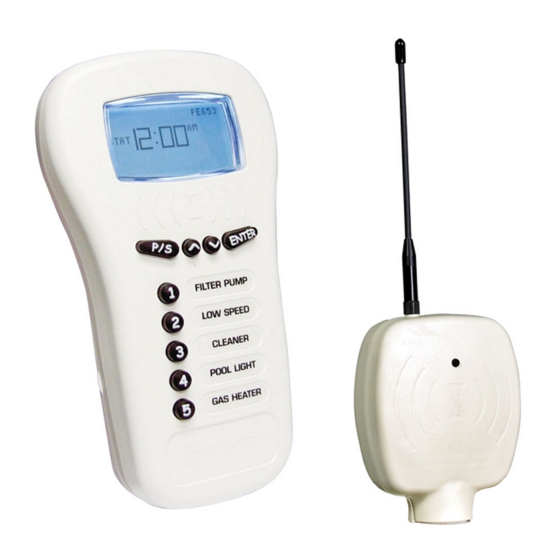
I-Wave PE950/PE650 Installation Guide Section 1: Overview The Intermatic I-Wave PE650 and PE950 make it possible to add wireless capability to a wide variety of pool and/or spa control systems. The PE650 Panel-Mounted Transceiver receives commands from the PE950 Hand-Held Transceiver to provide convenient, affordable, wireless control. -
Page 5: The Wireless Hand-Held Transceiver (Pe950)
(3) AA batteries. Battery life is about one year in typical use. The Wireless Hand-Held Transceiver can communicate only with the Panel-Mounted Transceiver, and is compatible with no other hardware. In addition, when the components Providing a brighter solution.™ Overview... - Page 6 I-Wave PE950/PE650 Installation Guide of a specific system are linked together into a network, communication with another neighboring system cannot occur. Up to five units can be used in a single installation. Copyright © 2006 Intermatic, Inc.
-
Page 7: Section 2: Installing The Panel-Mounted Transceiver
Section 2: Installing the Panel- Mounted Transceiver The Panel-Mounted Transceiver (PE650) mounts through a hole at the top of the steel enclosure just above the low voltage raceway, and — depending on the specifics of the installation — plugs into the Three-... -
Page 8: Connecting Wiring
I-Wave PE950/PE650 Installation Guide Connecting Wiring Plug the Panel-Mounted Transceiver wires into the mechanism(s) that make up the installation. During installation, be careful of the following: • Remove power when plugging the panel- mounted transceiver to any mechanism. • Respect polarity of the plug. DO NOT connect backwards. -
Page 9: Connecting A Water Temperature Sensor (Optional)
Connecting a Water Temperature Sensor (optional) The Intermatic I-Wave PE650 and PE950 wireless components can monitor water temperature with use of an Intermatic Water Temperature Sensor (PA122). The Intermatic water temperature sensor (PA122) is required to monitor either or both the pool and spa water temperatures,... -
Page 10: Connecting A Heater (Optional)
Connect both wires to the Panel-Mounted Receiver. See the diagram below. Connecting a Heater (optional) The Intermatic I-Wave PE650 and PE950 wireless components can control most heaters or heat pumps that use thermostatic circuitry of 24 VAC @ 2A or... -
Page 11: If Cool Down Period Is Required
Refer to the diagram and instructions below for connecting both the Panel Mount Receiver (PE650) and Three Circuit Clock Mechanism to your heater. Refer to the Cool Down Programming instructions in your P1353ME manual for cool down programming setup. -
Page 12: If Cool Down Period Is Not Required
I-Wave PE950/PE650 Installation Guide directly to one of the heater control wires. Cut in half the yellow loop wire on the back of the Three-Circuit Clock Mechanism. Connect one of the resulting yellow wires to the remaining heater control wire. -
Page 13: Connection For Teledyne Laars Heater
Install Panel-Mounted Transceiver Connection for Teledyne Laars Heater Connect two #14 gauge wires, designed for use in hot environments, to the two black wires, marked heater connection, on the panel-mounted receiver. Connect the other ends of the #14 gauge wires from Step 1 to the Fireman’s Switch terminal bar in place of the factory installed wire loop. -
Page 14: Connection For Raypak Heaters
I-Wave PE950/PE650 Installation Guide Connection for Raypak Heaters The following connection procedure is for the two wire-one function configuration Raypak heater. Connect two #14 gauge wires, designed for use in hot environments, to the two black wires on the panel-mounted receiver. -
Page 15: Connection For Hayward Heaters
Install Panel-Mounted Transceiver Connection for Hayward Heaters Remove service door on Heater. Remove factory- installed wire connector between two (2) red wires labeled “CONNECTION FOR FIELD INSTALLED CONTROL SWITCH.” Connect two #14 gauge wires, designed for use in hot environ- ments, to the two red wires. -
Page 16: Connection For Pentair Heater
I-Wave PE950/PE650 Installation Guide Connection for Pentair Heater Remove heater service door on your Pentair Heater. Separate the black wires (common) from each other. Connect two #14 gauge wires, designed for use in hot environ- ments, to the two black... -
Page 17: Connection For Sta-Rite Heaters
Install Panel-Mounted Transceiver Connection for Sta-Rite Heaters Turn off power to heater at main circuit breaker panel. Unbolt and remove the upper jacket halves (Refer to heater owners manual). Open control box cover. Remove the factory-installed jumper between the Fireman’s Switch terminals. - Page 18 I-Wave PE950/PE650 Installation Guide terminals at the heater. You can also cut the yellow jumper wire and wire connect the black wires to each yellow wire. Route the wires out through the knockout on the bottom of the Control Box.
-
Page 19: Section 3: Setting Up The Hand-Held Remote Transceiver
Section 3: Setting Up the Hand-Held Remote Transceiver Overview The Hand-Held Remote Transceiver (PE950) is the focal point of user convenience, its buttons controlling functions according to the specifics of the installation. Display Screen Display Screen ON/OFF ON/OFF Function Function... -
Page 20: Deleting Any Existing Programming
I-Wave PE950/PE650 Installation Guide The display panel on the unit provides pool and spa water temperature information, and makes it easy to control and program. “OK” means “OK” means Hand-Held Hand-Held is communicating is communicating with panel-mounted with panel-mounted transceiver transceiver “POOL”... - Page 21 Setting Up Hand-Held Remote Transceiver NOTE: If the word FAILURE instead of SUCCESS appears at the bottom of the screen during any of the following steps, repeat the programming procedure, then try replacing the batteries in the Hand-Held. If the problem persists, refer to appropriate troubleshooting procedures beginning on page 42.
- Page 22 I-Wave PE950/PE650 Installation Guide Press and release the <4> function button to select RESET CONTROLLER. The screen refreshes and displays only the line 4 RESET CONTROLLER, then returns to the full screen with the word SUCCESS at the bottom, as shown..
-
Page 23: Linking The Hand-Held Remote To The Panel-Mounted Transceiver
Setting Up Hand-Held Remote Transceiver Linking the Hand-Held Remote to the Panel-Mounted Transceiver If necessary, press and release any button on the Hand-Held Remote to wake it from sleep. (The unit goes to sleep to conserve battery life when it has been idle for 60 seconds.) The screen display on the... - Page 24 I-Wave PE950/PE650 Installation Guide Push and release the black button on the base of the Panel-Mounted Transceiver. The screen returns to the full screen with the word SUCCESS at the bottom, as shown. Press and release the <2> function button to select ADD TO GROUP.
-
Page 25: Testing I-Wave Reception
Setting Up Hand-Held Remote Transceiver NOTE: If the two devices have not successfully reset or linked together — and you are seeing only the word STAT on the left side of the screen — it’s likely that old programming still exists in either device. -
Page 26: Option One: The 35-Ft. Antenna Extension Cable (Pa121)
I-Wave PE950/PE650 Installation Guide Option One: The 35-ft. Antenna Extension Cable (PA121) The Antenna Extension Cable lets you move the antenna into direct line of sight from the area of operation — where the home owner will be using the Hand-Held Remote. - Page 27 Wait a few seconds for commands you enter on the Hand-Held Remote to register. Plug a Transceiver Repeater Module (HA04C), available from Intermatic, into any electrical outlet that is located where you have determined a reception problem can be solved.
- Page 28 I-Wave PE950/PE650 Installation Guide NOTE: If you pause in the programming procedure for 30 seconds, the screen automatically returns to Step 2. Press and release the <3> function button to select RESET NODE. The screen refreshes and displays only the line 3 RESET NODE, as shown.
- Page 29 Setting Up Hand-Held Remote Transceiver Press and release the <2> function button on the Hand-Held to select ADD TO GROUP. The screen refreshes and displays only the line 2 ADD TO GROUP. Push and release the black button on the base of the Panel-Mounted Transceiver.
-
Page 30: Everyday Use Of The Hand-Held Controller
I-Wave PE950/PE650 Installation Guide Everyday Use of the Hand-Held Controller The complete everyday functionality of the pool/spa system you have installed can be conveniently controlled using the Hand-Held Remote. Changing between Pool and Spa If Valve Actuator (PE24VA) is installed in the system, it directs water either to the pool or the spa. - Page 31 NOTE: The large temperature display shown on the Hand-Held Remote Screen reflects the current water temperature of the Pool or Spa, depending on which mode is active. Setting Up Hand-Held Remote Transceiver Providing a brighter solution.™ STAT STAT ºF SET ºF SET...
-
Page 32: Setting Pool And Spa Temperatures
I-Wave PE950/PE650 Installation Guide Setting Pool and Spa Temperatures If connected and linked, the Hand-Held Remote can control the independent water temperatures of both the pool and spa. View the current temperature on the right side of the Hand-Held Remote Screen under the word SET. -
Page 33: Operating Programmed Functions
Setting Up Hand-Held Remote Transceiver Operating Programmed Functions Depending on how you have wired the system, the five function buttons on the Hand-Held Remote control the five circuits in the Control Center. You should apply the appropriate label to the five buttons —... -
Page 34: Changing Batteries
I-Wave PE950/PE650 Installation Guide Changing Batteries The Hand- Held Remote Transceiver requires three (3) AA batteries. Battery life is about one year in typical use. To change batteries, use a small Phillips screwdriver to remove the three screws on the back of the unit, as indicated. -
Page 35: Manually Turning Equipment On/Off
SECONDARY. You can tell the status of a controller from the VER (version) code at the top of the display: the letter “P” = PRIMARY; the letter “S” = SECONDARY. Setting Up Hand-Held Remote Transceiver Providing a brighter solution.™ LEA RN LEA RN... - Page 36 I-Wave PE950/PE650 Installation Guide The PRIMARY controller must be used to “introduce” or link any additional (SECONDARY) Hand-Held units to the Control Center. If the PRIMARY controller must be replaced (due to loss, damage, etc.,), you must reprogram from scratch to create a new...
- Page 37 Setting Up Hand-Held Remote Transceiver On the NEW Hand-Held you are adding to the network: Press and release the <5> button to select MORE OPTIONS. A new screen will appear, as shown. Press and release the <2> button on the...
-
Page 38: Programming To Protect A Pool Cleaner Pump
I-Wave PE950/PE650 Installation Guide Programming to Protect a Pool Cleaner Pump If your equipment pad facilitates both a pool and spa and includes a booster pump, you will want to make sure the booster pump is never powered on when the system is in the spa mode. -
Page 39: Using Two Hand-Held Controllers To Operate The System
Setting Up Hand-Held Remote Transceiver NOTE: This button toggles between ON and OFF. That’s it. When Booster is set to ON: • The system will automatically turn the cleaner pump OFF any time the spa mode is activated, protecting the cleaner pump. -
Page 40: Calibrating The Temperature Display
I-Wave PE950/PE650 Installation Guide The owner can add up to 5 Hand-Held Controllers to a system. Calibrating the Temperature Display If the homeowner is using a floating thermometer or other device to measure water temperature, there may be discrepancy between that device and the temperature shown on the Hand-Held Remote. - Page 41 Setting Up Hand-Held Remote Transceiver Press and release the <3> button on the new screen to select ADJUST TEMP 0. Use the <UP> or <DOWN> arrow keys to add or subtract degrees shown by the Hand-Held display. For example, if you stop at ADJUST...
-
Page 42: Section 4: Check Out And Troubleshooting
I-Wave PE950/PE650 Installation Guide Section 4: Check out and Troubleshooting After you have completed installation and programming, make sure the system is working OK by completing the procedures listed below. Later on, if problems develop in using the system, going over these same procedures will help you troubleshoot the problem. - Page 43 If it doesn’t work Verify that batteries are installed properly and fully charged. Verify that the Hand-Held Remote has successfully awakened from its sleep state. Providing a brighter solution.™ Check Out and Troubleshooting Reference/Procedure The Hand-Held Remote takes 3 AAA batteries. Make sure the batteries are installed and are properly aligned according to the polarity markings in the battery...
- Page 44 I-Wave PE950/PE650 Installation Guide If it doesn’t work Verify that the Hand-Held Remote is successfully linked up to the Panel- mounted Transceiver. Verify that the Hand-Held Remote is controlling pool and spa temperature What to do Wake up the Hand-Held Remote by pressing any button.
- Page 45 Press the <ARROW> buttons to lower the set temperature below the actual water temperature. Verify that the word HEATING goes out at the bottom of the display. This indicates that the heater should not be heating, if the heater is working properly and the system is wired and plumbed properly.
- Page 46 I-Wave PE950/PE650 Installation Guide If it doesn’t work Verify that the Pool and Spa Set point on the Hand- Held Remote is set higher than the actual water temperature shown on its display. Verify that the Fireman switch wires from...
- Page 47 If the heater does not work independently of the control, repair the heater. If the heater does work independently of the control, replace the Panel-Mounted Transceiver. See page 4 for ordering information. Reference/Procedure Follow the troubleshooting procedures on page 42. Providing a brighter solution.™...
- Page 48 I-Wave PE950/PE650 Installation Guide If it doesn’t work Verify that the Hand-Held Remote is successfully communicating with the Panel- mounted Transceiver. Install Transceiver Repeater Modules (HA04C) where necessary to improve or broaden range. Reference/Procedure Stand next to the control box with the Hand-Held Remote.
- Page 49 Hand-Held Remote will be most frequently used. Mount the cable and antenna with the mounting kit that comes with the Intermatic 35-ft. Antenna Extension Cable Assembly (PA121). Repeat the “What to do” procedure to verify that your...
- Page 50 I-Wave PE950/PE650 Installation Guide Check that the buttons operate the correct relays What to do Wake up the Hand-Held Remote by pressing any button. Standing near the Control Center so you can observe the relays clicking, press buttons <1> through <5>.
- Page 51 VALVE light on the control is OFF. Push Circuit #1 ON to turn on the Filter Pump. Wake up the Hand-Held Remote Transceiver by pressing any button. The display should show the actual water temperature of the pool.
- Page 52 I-Wave PE950/PE650 Installation Guide If it doesn’t work Verify that the Three-Circuit Clock and Pump/Valve switch are working properly. Verify heater and wireless system are working properly together. Verify a Fireman’s Switch delay time has been programmed in the Three Circuit Clock.
-
Page 53: Installation Notes
Installation Notes ______________________________________________ ______________________________________________ ______________________________________________ ______________________________________________ ______________________________________________ ______________________________________________ ______________________________________________ ______________________________________________ ______________________________________________ ______________________________________________ ______________________________________________ ______________________________________________ ______________________________________________ ______________________________________________ ______________________________________________ ______________________________________________ ______________________________________________ ______________________________________________ ______________________________________________ ______________________________________________ ______________________________________________ Providing a brighter solution.™... - Page 54 I-Wave PE950/PE650 Installation Guide Installation Notes ______________________________________________ ______________________________________________ ______________________________________________ ______________________________________________ ______________________________________________ ______________________________________________ ______________________________________________ ______________________________________________ ______________________________________________ ______________________________________________ ______________________________________________ ______________________________________________ ______________________________________________ ______________________________________________ ______________________________________________ ______________________________________________ ______________________________________________ ______________________________________________ ______________________________________________ ______________________________________________ ______________________________________________ Copyright © 2006 Intermatic, Inc.
- Page 55 Installation Notes ______________________________________________ ______________________________________________ ______________________________________________ ______________________________________________ ______________________________________________ ______________________________________________ ______________________________________________ ______________________________________________ ______________________________________________ ______________________________________________ ______________________________________________ ______________________________________________ ______________________________________________ ______________________________________________ ______________________________________________ ______________________________________________ ______________________________________________ ______________________________________________ ______________________________________________ ______________________________________________ ______________________________________________ Providing a brighter solution.™...
- Page 56 Intermatic, Inc. 7777 Winn Road Spring Grove, Illinois 60081-9698 www.intermatic.com Intermatic Customer Service: 815-675-7000 (8 a.m. through 4:30 p.m. CT, Monday through Friday) ©2006 Intermatic, Inc. Printed in U.S.A. 158PE12840...