Table of Contents
Advertisement
Industrial Automation Headquarters
Delta Electronics, Inc.
Taoyuan Technology Center
No.18, Xinglong Rd., Taoyuan City,
Taoyuan County 33068, Taiwan
TEL: 886-3-362-6301 / FAX: 886-3-371-6301
Asia
Delta Electronics (Jiangsu) Ltd.
Wujiang Plant 3
1688 Jiangxing East Road,
Wujiang Economic Development Zone
Wujiang City, Jiang Su Province, P.R.C. 215200
TEL: 86-512-6340-3008 / FAX: 86-769-6340-7290
Delta Greentech (China) Co., Ltd.
238 Min-Xia Road, Pudong District,
ShangHai, P.R.C. 201209
TEL: 86-21-58635678 / FAX: 86-21-58630003
Delta Electronics (Japan), Inc.
Tokyo Office
2-1-14 Minato-ku Shibadaimon,
Tokyo 105-0012, Japan
TEL: 81-3-5733-1111 / FAX: 81-3-5733-1211
Delta Electronics (Korea), Inc.
1511, Byucksan Digital Valley 6-cha, Gasan-dong,
Geumcheon-gu, Seoul, Korea, 153-704
TEL: 82-2-515-5303 / FAX: 82-2-515-5302
Delta Electronics Int'l (S) Pte Ltd.
4 Kaki Bukit Ave 1, #05-05, Singapore 417939
TEL: 65-6747-5155 / FAX: 65-6744-9228
Delta Electronics (India) Pvt. Ltd.
Plot No 43 Sector 35, HSIIDC
Gurgaon, PIN 122001, Haryana, India
TEL : 91-124-4874900 / FAX : 91-124-4874945
Americas
Delta Products Corporation (USA)
Raleigh Office
P.O. Box 12173,5101 Davis Drive,
Research Triangle Park, NC 27709, U.S.A.
TEL: 1-919-767-3800 / FAX: 1-919-767-8080
Delta Greentech (Brasil) S.A.
Sao Paulo Office
Rua Itapeva, 26 - 3° andar Edificio Itapeva One-Bela Vista
01332-000-São Paulo-SP-Brazil
TEL: 55 11 3568-3855 / FAX: 55 11 3568-3865
Europe
Deltronics (The Netherlands) B.V.
Eindhoven Office
De Witbogt 15, 5652 AG Eindhoven, The Netherlands
TEL: 31-40-2592850 / FAX: 31-40-2592851
*We reserve the right to change the information in this manual without prior notice.
DELTA_IA-ASDA-A2R_UM_EN_20141219 (V2.0)
A High Performance with
Diverse Communication
Interfaces Servo Drive
ASDA-A2R Series User
Manual
www.deltaww.com
Advertisement
Table of Contents

Related Manuals for Delta ASD-A2R-0221 Series


Summary of Contents for Delta ASD-A2R-0221 Series
- Page 1 1511, Byucksan Digital Valley 6-cha, Gasan-dong, Geumcheon-gu, Seoul, Korea, 153-704 A High Performance with TEL: 82-2-515-5303 / FAX: 82-2-515-5302 Delta Electronics Int’l (S) Pte Ltd. 4 Kaki Bukit Ave 1, #05-05, Singapore 417939 Diverse Communication TEL: 65-6747-5155 / FAX: 65-6744-9228 Delta Electronics (India) Pvt.
- Page 2 Preface Thank you for purchasing ASDA-A2R. This user manual provides the related information of ASDA-A2R series servo drive and ECMA, ECML series servo motors. This manual includes: Installation and inspection of servo drive and servo motor The configuration of servo drive ...
- Page 3 PrefaceASDA-A2R Series Safety Precautions ASDA-A2R series is the high resolution and open type servo drive. It should be installed in a shielded control box during operation. This servo drive uses precise feedback control and the digital signal processor with high-speed calculation function to control the current output which generated by IGBT so as to operate three-phase permanent magnet synchronous motors (PMSM) and to achieve precise positioning.
- Page 4 PrefaceASDA-A2R Series Operation Before the operation, please change the parameter setting value according to the needs. If it is not adjusted to the correct setting value, it is possible to lead to malfunction of the machine or the operation might out of control. Before the machine starts to operate, please be ensured the emergency stop ...
- Page 5 When inserting the electric wires, do not connect the conductor to the adjacent wire. Before connecting to the power, please inspect and be ensured the wiring is correct. NOTE If there is any difference of each version, please refer to DELTA’s website (http://www.delta.com.tw/industrialautomation/) for the latest information. Revision December, 2014...
- Page 6 Improper installation is prohibited, such as to knock, to cut off, to stamp on or to tighten incorrect mechanism. NOTE If there is any difference of each version, please refer to DELTA’s website (http://www.delta.com.tw/industrialautomation/) for the latest information. Revision December, 2014...
-
Page 7: Table Of Contents
Specification of Circuit Breaker and Fuse ............2-4 EMI Filters Selection ..................2-5 Selection of Regenerative Resistor ............... 2-7 Chapter 3 Wiring Wiring of Delta’s Servo System ..............3-1 3.1.1 Wiring Diagram of Peripheral Devices (connect to Delta’s Servo Motor Communication Type) ................3-1 Revision December, 2014... - Page 8 Table of ContentsASDA-A2R Series 3.1.2 Connectors and Terminals of the Servo Drive ........3-3 3.1.3 Wiring Method ..................3-5 3.1.4 Specification of ECMA Motor U, V, W Power Cable ......3-7 Specification of ECML Motor U, V, W Power Cable ......3-9 3.1.5 Specification of Connector of Encoder Cable ........
- Page 9 Table of ContentsASDA-A2R Series 3.10.1 Position (PT) Mode Standard Wiring ..........3-53 3.10.2 Position (PR) Mode Standard Wiring ..........3-54 3.10.3 Speed Mode Standard Wiring ............. 3-55 3.10.4 Torque Mode Standard Wiring ............3-56 3.10.5 CANopen Mode Standard Wiring ............3-57 3.11 Wiring System of other Brand of Motor ............
- Page 10 Table of ContentsASDA-A2R Series 4.4.4 Digital Input Diagnosis Operation ............4-12 4.4.5 Digital Output Diagnosis Operation ............4-12 Chapter 5 Trial Operation and Tuning Inspection without Load ................. 5-1 Apply Power to the Servo Drive ..............5-2 JOG Trial Run without Load ................5-5 Trial Run without Load (Speed Mode) ............
- Page 11 Table of ContentsASDA-A2R Series 6.2.2 Position Command in PR Mode ............6-3 6.2.3 Control Structure of Position Mode ............6-4 6.2.4 S-Curve Filter (Position) ............... 6-6 6.2.5 Electronic Gear Ratio ................6-8 6.2.6 Low-pass Filter ..................6-9 6.2.7 Timing Diagram in Position Mode (PR) ..........6-10 6.2.8 Gain Adjustment of Position Loop ............
- Page 12 Table of ContentsASDA-A2R Series 6.5.1 Speed / Position Dual Mode ..............6-36 6.5.2 Speed / Torque (force) Dual Mode ............6-36 6.5.3 Torque (force) / Position Dual Mode ............. 6-37 Others ......................6-38 6.6.1 The Use of Speed Limit ................ 6-38 6.6.2 The Use of Torque (force) Limit ............
- Page 13 Table of ContentsASDA-A2R Series 7.10.2 Programming the Path in PR Mode ............ 7-24 7.11 The Description of E-Cam Function ............... 7-26 7.11.1 Function Description of CAPTURE (Data Capture) ......7-34 7.11.2 Function Description of COMPARE (Data Compare) ......7-36 Chapter 8 Parameters Parameter Definition ..................
- Page 14 Table of ContentsASDA-A2R Series RS-485/RS-232 Communication Parameters Setting ......... 9-3 MODBUS Communication Protocol ............... 9-4 Write-in and Read-out Communication Parameters ........9-15 Chapter 10 Toubleshooting 10.1 Alarm of Servo Drive ..................10-1 10.2 Alarm of CANopen Communication ............... 10-4 10.3 Alarm of Motion Control .................
-
Page 15: Revision
Table of ContentsASDA-A2R Series 12.2 Panel Setup Procedure (without PC Software)..........12-24 Appendix A Accessories Appendix B Maintenance and Inspection Revision December, 2014... - Page 16 Table of ContentsASDA-A2R Series (This page is intentionally left blank.) Revision December, 2014...
-
Page 17: Chapter 1 Inspection And Model Explanation
Chapter 1 Inspection and Model Explanation 1.1 Inspection In order to prevent the negligence during purchasing and delivery, please inspect the following items carefully. Please check if the product is what you have purchased: check the part number of the motor and the servo drive on the nameplate. - Page 18 Chapter 1 Inspection and Model Explanation ASDA-A2R Series (13) 3-PIN fast connector (U, V, W) (14) 3-PIN fast connector (P , D, C) (15) A plastic lever (16) A metal short-circuit chip (17) An installation manual Revision December, 2014...
-
Page 19: Product Model
Nameplate Information Model Name Power Input Specification Power Output Specification Barcode Serial Number Serial Number Serial Number Production Week Production Year (8: Year of 2008) Production Factory (T: Taoyuan; W: Wujiang) Delta Standard Model Name Revision December, 2014... - Page 20 Chapter 1 Inspection and Model Explanation ASDA-A2R Series ECML Series Servo Motor Coil Assembly_Nameplate Information Coil assembly_Serial Number Magnetic way_ Nameplate Information Magnetic way_ Serial Number Revision December, 2014...
-
Page 21: Model Explanation
Chapter 1 Inspection and Model Explanation ASDA-A2R Series 1.2.2 Model Explanation ASDA-A2R Series Servo Drive A S D - A 2 R - 0 1 2 1 - U Model Type Input Voltage and Phase 21: 220 V 1 phase 23: 220 V 3 phase Rated Power Input 01: 100 W... - Page 22 Chapter 1 Inspection and Model Explanation ASDA-A2R Series ECMA Series Servo Motor E C M A - C 1 0 6 0 2 E S Standard Shaft Diameter: S Specific Shaft Diameter: 3=42mm, 7=14mm with With Type of Shaft Brake Brake Brake Brake...
- Page 23 Chapter 1 Inspection and Model Explanation ASDA-A2R Series ECML Series Servo Motor_Magnetic Way ECM L - S M 16 1000 S Total length of magnetic way 0340: 340 mm 0520: 520 mm 0700: 700 mm 0880: 880 mm 1060: 1060 mm 1240: 1240 mm Magnetic way dimensions 16: Ø16 mm...
- Page 24 Chapter 1 Inspection and Model Explanation ASDA-A2R Series ECML Series Servo Motor_Coil assembly ECM L - S 08 A 2 D N S Cooling type A: Air cooling L: Water cooling N: N/A Hall sensor type A: Analog D: Digital Input voltage 2: 220V 3: 380V...
-
Page 25: Servo Drive And Corresponding Servo Motor
Chapter 1 Inspection and Model Explanation ASDA-A2R Series 1.3 Servo Drive and Corresponding Servo Motor Permanent magnet Permanent magnet Servo Drive synchronous rotary motor synchronous linear motor (ECMA-) (ECML-) ECML-S1606A2DNS ECMA-C△0401S (S = 8 mm) 100 W ASD-A2R-0121- ECML-S1608A2DNS ECMA-C1040FS (S = 8 mm) ECML-S2003A2DNS 200 W ASD-A2R-0221-... -
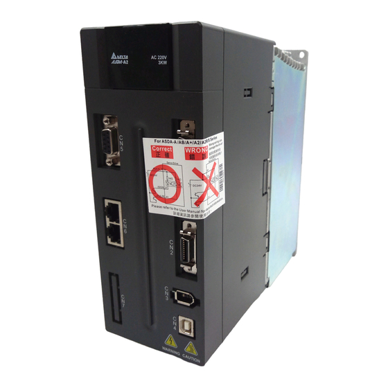
Page 26: Each Part Of The Servo Drive
Chapter 1 Inspection and Model Explanation ASDA-A2R Series 1.4 Each Part of the Servo Drive Front view of the servo drive Please refer to the top view Sliding cover Indicator of input voltage CN5: Connector Connect to linear scale CN1: Connector Connect to PLC or control I/O CN6: CANopen connector Connector for communication control... - Page 27 Chapter 1 Inspection and Model Explanation ASDA-A2R Series Top view of the servo drive Revision December, 2014 1-11...
- Page 28 Chapter 1 Inspection and Model Explanation ASDA-A2R Series Bottom view of the servo drive Servo Motor Output Reserved connector Connect to motor power connector (U,V,W) and cannot connect to the main circuit power. Grounding Terminal Wrong connection may damage the servo drive. Connect to power and motor grounding 1-12...
-
Page 29: Ecml Series Servo Motor
Chapter 1 Inspection and Model Explanation ASDA-A2R Series 1.5 ECML Series Servo Motor Encoder cable It contains 7 core cables, which are for Hall Sensor and NTC thermistor. It connects to CN2 or CN5. Please refer to Ch3.1 for wiring method. Motor power cable It contains 4 core cables, which are for U, V, W and ground wire. - Page 30 Chapter 1 Inspection and Model Explanation ASDA-A2R Series (This page is intentionally left blank.) 1-14 Revision December, 2014...
-
Page 31: Chapter 2 Installation
Chapter 2 Installation 2.1 Notes Please pay special attention to the followings: 1) Do not strain the cable connection between the servo drive and the servo motor. 2) Make sure each screw is tightened when fixing the servo drive. 3) The motor shaft and the ball screw should be parallel. 4) If the connection between the servo drive and the servo motor is over 20 meters, please thicken the connecting wire, UVW as well as the encoder cable. -
Page 32: Ambient Conditions Of Installation
Chapter 2 InstallationASDA-A2R Series 2.3 Ambient Conditions of Installation The best temperature of this servo drive is between 0 ℃ and 55 ℃. If the temperature is over 45 ℃, please place the product in a well-ventilated environment so as to ensure its reliability performance. -
Page 33: Installation Direction And Space
Chapter 2 InstallationASDA-A2R Series 2.4 Installation Direction and Space Notes: Follow the instructions for installation direction. Otherwise it is possible to cause malfunction. In order to have well-cooling and circulation effect, the enough space between adjacent objects and the baffle is needed. Or it might result in malfunction. When installing AC servo drive, do not seal the suction hole and the vent hole. -
Page 34: Specification Of Circuit Breaker And Fuse
Chapter 2 InstallationASDA-A2R Series 2.5 Specification of Circuit Breaker and Fuse Caution: Please use the fuse and circuit breaker that is recognized by UL/CSA. Servo Drive Model Circuit breaker Fuse (Class T) Operation Mode General General ASD-A2R-0121- ASD-A2R-0221- ASD-A2R-0421- ASD-A2R-0721- ASD-A2R-1021-... -
Page 35: Emi Filters Selection
With EMI Filter and the correct installation, much interference can be eliminated. It is suggested to use Delta’s EMI Filter to suppress the interference better. When installing servo drive and EMI Filter, please follow the instructions of the user manual and make sure it meets the following specification. - Page 36 Chapter 2 InstallationASDA-A2R Series Motor Cable Selection and Installation Precautions The selection of motor cables and installation affect the performance of EMI Filter. Please follow the precautions mention below. 1. Use the cable that has braid shielding (The effect of double shielding is better) 2.
-
Page 37: Selection Of Regenerative Resistor
Chapter 2 InstallationASDA-A2R Series 2.7 Selection of Regenerative Resistor When the direction of pull-out torque is different from the rotation, it means the electricity is sent back to the servo drive from the load-end. It becomes the capacitance of DC Bus and increases the voltage. - Page 38 Chapter 2 InstallationASDA-A2R Series Rotary Motor: Regenerative Power Selection (a) When the external load on torque does not exist If the motor operates back and forth, the energy generated by the brake will go into the capacitance of DC bus. When the voltage of the capacitance exceeds a specific value, the redundant energy will be consumed by regenerative resistor.
- Page 39 Chapter 2 InstallationASDA-A2R Series Assume the load inertia is N times to the motor inertia and the motor decelerates from 3000r/min to 0, its regenerative energy is (N+1) x Eo. The consumed regenerative resistor is (N+1) × Eo - Ec joule.
- Page 40 Chapter 2 InstallationASDA-A2R Series 馬 達 轉 速 Motor Speed 外 部 負 載 扭 矩 External Load Torque 馬 達 輸 出 扭 矩 Motor Output Torque 正功 馬 達 輸 出 負 功 正 功 負 功 Negative Positive Negative Positive...
- Page 41 Chapter 2 InstallationASDA-A2R Series according to different load inertia or speed. The following is the calculation method. m represents load / motor inertia ratio. times Allowable frequency when serv o motor run without load Rated s peed Allowable fr equency = mi n.
- Page 42 Chapter 2 InstallationASDA-A2R Series Allowable frequency of regenerative resistor when the servo drive runs without load (times/min) ECMA□ □ L Motor Capacity 11 kW 15 kW Corresponding Motor BR400W040 (400 W 40Ω) BR1K0W020 (1 kW 20Ω) 2-12 Revision December, 2014...
- Page 43 Chapter 2 InstallationASDA-A2R Series Linear Motor: Regenerative Power Selection (a) When the external load on torque does not exist If the motor operates back and forth, the energy generated by the brake will go into the capacitance of DC bus. When the voltage of the capacitance exceeds a specific value, the redundant energy will be consumed by regenerative resistor.
- Page 44 Chapter 2 InstallationASDA-A2R Series Steps Item Calculation and Setting Method Calculate the maximum E = 0.5 mv2 regenerative energy E Set the absorbable regenerative Refer to the above table energy Ec Calculate the needful capacitance 2 × (E – Ec) / T of regenerative resistor Take 400W as the example, the cycle of back and forth operation is T = 0.4sec, assume that the maximum speed is 2m/s and the total weight of movable section and...
- Page 45 Chapter 2 InstallationASDA-A2R Series For safety reasons, please calculate it by considering the safest situation. For example, when the external force is the +70% rated force and the speed reaches 2m/s, then take 400W (rated force is FN) as the example, the user has to connect the regenerative resistor which is 2 ×...
- Page 46 Chapter 2 InstallationASDA-A2R Series (2) Simple Selection Choose the appropriate regenerative resistor according to the allowable frequency and empty load frequency in actual operation. The so-called empty allowable frequency is the maximum frequency of continuous operation when the servo motor runs from 0m/s to 5m/s and then from 5m/s to 0r/min.
- Page 47 Chapter 2 InstallationASDA-A2R Series Dimensions of Regenerative Resistor Delta part number: BR400W040 (400 W 40Ω) MAX. WEIGHT (g) Delta part number: BR1K0W020 (1 kW 20Ω) MAX. WEIGHT (g) 2800 Revision December, 2014 2-17...
- Page 48 Chapter 2 InstallationASDA-A2R Series Delta part number: BR1K5W005 (3 kW 10Ω) 2-18 Revision December, 2014...
-
Page 49: Chapter 3 Wiring
L c are correct. 2. When connecting to Delta’s 20bit rotary motor, please check if the output terminal U, V, W of the servo motor is correctly wired. The incorrect wiring may disable the operation of the motor or cause malfunction. - Page 50 Magnetic Contactor (MC) When an alarm occurs, it could output ALRM signal and disconnect the power of the servo drive. Host Controller It could connect to Delta’s PLC controller or other NC controller. Regenerative Resistor (option) Terminal Block Module(ASD-BM-50A)
-
Page 51: Connectors And Terminals Of The Servo Drive
Chapter 3 Wiring ASDA-A2R Series 3.1.2 Connectors and Terminals of the Servo Drive Terminal Name Description Signal Power input Connect single-phase power (select L1c, L2c control circuit appropriate voltage specification according to the product ) Power input of the main Connect to three-phase AC power (select the appropriate R, S, T circuit... - Page 52 Chapter 3 Wiring ASDA-A2R Series Pay special attention to the followings when wiring: 1) When the power is cutoff, do not touch R, S, T and U, V, W since the capacitance inside the servo drive still contains huge amount of electric charge. Wait until the charging light is off.
-
Page 53: Wiring Method
Chapter 3 Wiring ASDA-A2R Series 3.1.3 Wiring Method The wiring method of ASDA-A2R servo drive is divided into single-phase and three-phase. In the diagram below, Power On is contact a, Power Off and ALRM_RY are contact b. MC is the coil of magnetic contactor and self-remaining power and is the contact of main power circuit. - Page 54 Chapter 3 Wiring ASDA-A2R Series Wiring Method of Three-phase Power Supply (suitable for all series) Revision December. 2014...
-
Page 55: Specification Of Ecma Motor U, V, W Power Cable
Chapter 3 Wiring ASDA-A2R Series 3.1.4 Specification of ECMA Motor U, V, W Power Cable Terminal U, V, W/Connector of Brake Motor Model Definition ECMA-C1040FS (50 W) ECMA-C△0401S (100 W) ECMA-C△0602S (200 W) ECMA-C△0604S (400 W) ECMA-C△08047 (400 W) ECMA-C△0807S (750 W) ECMA-C△0907S (750 W) ECMA-C△0910S (1000 W) ECMA-C1040FS (50 W) - Page 56 Chapter 3 Wiring ASDA-A2R Series Terminal U, V, W/Connector of Brake Motor Model Definition ECMA-E△1820S (2000 W) ECMA-E△1830S (3000 W) ECMA-E△1835S (3500 W) ECMA-F△1830S (3000 W) CASE Wiring BRAKE1 BRAKE2 GROUND Name (Red) (White) (Black) (Yellow) (Blue) (Green) Terminal Definition A Terminal Definition B Terminal...
-
Page 57: Specification Of Ecml Motor U, V, W Power Cable
Chapter 3 Wiring ASDA-A2R Series When selecting the wire rod, please choose 600V PVC cable and the length should not longer than 30m. If the length exceeds 30m, please take the received voltage into consideration when selecting the wire size. Please refer to Section 3.1.6 for wire rod selection. -
Page 58: Specification Of Connector Of Encoder Cable
Chapter 3 Wiring ASDA-A2R Series 3.1.5 Specification of Connector of Encoder Cable Encoder connection diagram 1: This diagram shows the connection between the servo drive and the NOTE motor encoder. It is not drew by the practical scale and specification will be different according to the selected servo drive and motor model. - Page 59 Chapter 3 Wiring ASDA-A2R Series Specification and Definition of Encoder Connector: Connector of Connector of Encoder Cable Motor Encoder Housing : AMP(1-172161-9) Servo Drive Motor Encoder View from View from this side this side (In servo motor models, encoder types are 17-bit and 20-bit.) White Blue Reserved...
- Page 60 Chapter 3 Wiring ASDA-A2R Series Encoder connection diagram 2: This diagram shows the connection between the servo drive and the NOTE motor encoder. It is not drew by the practical scale and specification will be different according to the selected servo drive and motor model. Please refer to Section 3.5, CN2 Connector.
-
Page 61: Specification And Definition Of Motor Signal Cable
Chapter 3 Wiring ASDA-A2R Series ECMA-E△1830S (3000 W) ECMA-F△1830S (3000 W) ECMA-E△1835S (3500 W) Please select shielded multi-core and the shielded cable should connect to the SHIELD end. Please refer to the description of Section 3.1.6. 1) Box, ( △ ) in servo motor model represents encoder type. △ =1: NOTE incremental, 20-bit;... -
Page 62: Selection Of Wire Rod
Chapter 3 Wiring ASDA-A2R Series 3.1.6 Selection of Wire Rod The recommended wire rods are shown as the following table. Servo Drive and corresponding Motor Power Wiring-Wire Diameter mm² (AWG) Model c, L R, S, T U, V, W P , C ECMA-C1040FS 1.3 (AWG16) 2.1 (AWG14) 0.82 (AWG18) 2.1 (AWG14) ASD-A2R -0121-... - Page 63 Chapter 3 Wiring ASDA-A2R Series 4) Box, () at the end of the servo drive model represents the model code of ASDA-A2. Please refer to the model information of the product you purchased. 5) Box, () in servo motor model represents brake or keyway / oil seal. Revision December, 2014 3-15...
-
Page 64: Schematic Diagram Of Servo System
Chapter 3 Wiring ASDA-A2R Series Schematic Diagram of Servo System ■ 220 V 400 W (included) model below (No built-in regenerative resistor) 3-16 Revision December. 2014... - Page 65 Chapter 3 Wiring ASDA-A2R Series ■ 220 V 750 W ~ 3 kW Model (Built-in Regenerative Resistor and Fan) External regenerative resistor Power 750 W ~ 1.5 kW Model Single/3-phase 200 ~ 230 V 2 kW ~ 3 kW Model 3-phase 200 ~ 230 V 750 W ~ 3 kW Model Servo Drive PRB 60W or 120W...
-
Page 66: I/O Signal (Cn1) Connection
Chapter 3 Wiring ASDA-A2R Series 3.3 I/O Signal (CN1) Connection 3.3.1 I/O Signal (CN1) Connector Terminal Layout In order to have a more flexible communication with the master, 5 programmable Digital Outputs (DO) and 8 programmable Digital Inputs (DI) are provided. The setting of 8 digital inputs and 5 digital outputs of each axis are parameter P2-10~P2-17 and parameter P2-18~P2-22 respectively. - Page 67 Chapter 3 Wiring ASDA-A2R Series DO4+ Digital output 26 DO4- Digital output Digital DO3- Digital output 27 DO5- output DO3+ Digital output 28 DO5+ Digital output High-speed position DO2- Digital output 29 /HPULSE command DO2+ Digital output 30 DI8- Digital input pulse (-) DO1- Digital output...
-
Page 68: Explanation Of I/O (Cn1) Connector Signal
Chapter 3 Wiring ASDA-A2R Series 3.3.2 Explanation of I/O (CN1) Connector Signal The following details the signals listed in previous section: General Signals Wiring Method Signal Name Pin No Function (Refer to 3.4.3) (1) The speed command of the motor is -10 V ~ +10 V which means the speed command is -3000 ~ +3000 r/min (default). - Page 69 Chapter 3 Wiring ASDA-A2R Series Wiring Method Signal Name Pin No Function (Refer to 3.4.3) VDD is the +24 V power provided by the drive and is for Digital Input (DI) and Digital Output (DO) signal. The maximum current is 500 mA.
- Page 70 Chapter 3 Wiring ASDA-A2R Series Pin No Wiring DO Signal Method Operation Mode Function + - Name (Refer to 3.4.3) When the motor speed is slower than ZSPD the setting value of parameter P1-38, this DO is ON. When the motor actual speed (r/min) ALL (except PT, TSPD is faster than the setting value of...
- Page 71 Chapter 3 Wiring ASDA-A2R Series Pin No Wiring DO Signal Method Operation Mode Function + - Name (Refer to 3.4.3) SDO_A - Output the status of bit10 of P4-06 SDO_B - Output the status of bit11 of P4-06 SDO_C - Output the status of bit12 of P4-06 SDO_D - Output the status of bit13 of P4-06 SDO_E...
- Page 72 Chapter 3 Wiring ASDA-A2R Series The explanation of DI signal default setting is as the followings Wiring DI Signal Operation Method Function Name Mode (Refer to 3.4.3) When DI is ON, the servo circuit will be activated and the motor coil will generate current. When the alarm (ALRM) occurs, this signal is used to reset the ARST servo drive and output the signal, Ready (SRDY) again.
- Page 73 Chapter 3 Wiring ASDA-A2R Series Wiring DI Signal Operation Method Function Name Mode (Refer to 3.4.3) The source of selecting torque command: TCM1 TCM0 Command Source PT,T, TCM0 PT-T T mode is analog input while Tz mode is 0. P1-12 PR-T, P1-13 TCM1...
- Page 74 Chapter 3 Wiring ASDA-A2R Series Wiring DI Signal Operation Method Function Name Mode (Refer to 3.4.3) PT, PR, Electronic gear ratio (numerator) selection 0 (Please refer to GNUM0 PT-S, PR-S P2-60~P2-62 for gear ratio selection (numerator).) PT, PR, Electronic gear ratio (numerator) selection 1 (Please refer to C9/C10 GNUM1 PT-S, PR-S...
- Page 75 Chapter 3 Wiring ASDA-A2R Series The default setting of DI and DO in each operation mode is shown as the followings. Please note that the following table neither detail the information as the previous one nor show the Pin number of each signal. However, each operation mode is separated in different columns in order to avoid the confusion.
- Page 76 Chapter 3 Wiring ASDA-A2R Series Symbol Input Function PT PR Sz Tz Code between torque and position command Switch between PT PT-PR 0x2B and PR command In PT mode, the switch between PTAS 0x2C command pulse and analog In PT mode, the switch between PTCMS 0x2D...
- Page 77 Chapter 3 Wiring ASDA-A2R Series Table 3.2 Default Value of DO Output Function Symbol Output Function PT PR Sz Tz Code SRDY 0x01 Servo is ready DO1 DO1 DO1 DO1 DO1 DO1 DO1 DO1 DO1 DO1 DO1 0x02 Servo is On. ZSPD 0x03 Zero-speed DO2 DO2 DO2 DO2 DO2 DO2 DO2 DO2 DO2 DO2 DO2...
- Page 78 Chapter 3 Wiring ASDA-A2R Series Symbol Output Function PT PR Sz Tz Code SDO_9 0x39 Output the status of bit09 of P4-06 SDO_A 0x3A Output the status of bit10 of P4-06 SDO_B 0x3B Output the status of bit11 of P4-06 SDO_C 0x3C Output the status of bit12 of P4-06...
-
Page 79: Wiring Diagram (Cn1)
Chapter 3 Wiring ASDA-A2R Series 3.3.3 Wiring Diagram (CN1) The valid voltage of speed analog command and torque analog command is between -10V and +10V. The command value can be set via relevant parameters. The input impedance is 10K. C1: Speed, Input of Torque Analog Command C2: Analog Monitor Output MON1 ,MON2 Revision December, 2014 3-31... - Page 80 Chapter 3 Wiring ASDA-A2R Series Pulse command can be input by the way of open-collector or Line driver. The maximum input pulse of Line driver is 500 kpps and 200 kpps for open-collector. C3-1: The source of pulse input is open-collector NPN equipment which applies the internal power of the servo drive.
- Page 81 Chapter 3 Wiring ASDA-A2R Series C3-3: The source of pulse input is open-collector NPN equipment and applies the external power. C3-4: The source of pulse input is open-collector PNP equipment and applies the external power. Revision December, 2014 3-33...
- Page 82 Chapter 3 Wiring ASDA-A2R Series Caution: Do not apply to dual power or it may damage the servo drive. C4-1: Pulse input (Line driver) can only apply to 5V power. Do not apply to 24V power. This opto-isolator is one-way input, please be ensured the direction of ...
- Page 83 Chapter 3 Wiring ASDA-A2R Series The high-speed pulse input interface of the servo drive is not the isolated interface. In order to reduce the interference of the noise, it is suggested that the terminal ground of the controller and the servo drive should be connected to each other.
- Page 84 Chapter 3 Wiring ASDA-A2R Series C7: Wiring of DO signal. The servo drive applies to the external power and the resistor is general load. Servo Drive No connection between VDD and COM+ . DOX:(DOX+,DOX-) X=1,2,3,4,5 DO1:(7,6) DC24V DO2:(5,4) DOX+ DO3:(3,2) DO4:(1,26) DOX- DO5:(28,27)
- Page 85 Chapter 3 Wiring ASDA-A2R Series Input signal via relay or open-collector transistor NPN transistor, common emitter (E) mode (SINK mode) C9: The wiring of DI. The servo drive applies C10: The wiring of DI. The servo drive to the internal power. applies to the external power.
- Page 86 Chapter 3 Wiring ASDA-A2R Series C13: Encoder signal output (Line driver) Servo Drive Controller Max. output current 20mA AM26CS31 type OA 21 /OA 22 125Ω OB 25 /OB 23 125Ω OZ 50 /OZ 24 125Ω C14: Encoder signal output (Opto-isolator) 3-38 Revision December.
-
Page 87: The Di And Do Signal Specified By The User
Chapter 3 Wiring ASDA-A2R Series C15: Encoder OCZ output (open-collector Z pulse output) 3.3.4 The DI and DO Signal Specified by the User If the default setting of DI/DO signal cannot satisfy the need, self-set the DI/DO signal will do and easy. The signal function of DI1 ~ 8 and DO1 ~ 5 is determined by parameter P2-10 ~ P2-17 and parameter P2-18 ~ P2-22 respectively. -
Page 88: Application: Wiring Of Cn1 Quick Connector
Chapter 3 Wiring ASDA-A2R Series 3.3.5 Application: Wiring of CN1 Quick Connector ASD-IF-SC5020 CN1 quick connector is designed for easy wiring. It is applicable to ASDA-A2 and ASDA-A2R series servo drive and can satisfy the demand of different DI/O application. It will be a good choice for those who do not want to self-weld the wiring rods. The vibration will not loose the leading wire due to the design of spring terminal blocks. - Page 89 Chapter 3 Wiring ASDA-A2R Series Description Description COM+ COM+ COM- 2,4,6,26,45,47 COM- DI1- DI1- DI2- DI2- DI3- DI3- DI4- DI4- DI7- DI7- DO1+ DO1+ DO2+ DO2+ PULL_HI_PS PULL_HI_PS /PULSE /PULSE PULSE PULSE /SIGN /SIGN SIGN SIGN 12,13,19,44 DO4+ DO4+ DO3+ DO3+ CN_GND 51,52...
- Page 90 Chapter 3 Wiring ASDA-A2R Series Wiring and installation of CN1 quick connector: Wiring: Installation: 3-42 Revision December. 2014...
-
Page 91: Cn2 Connector
Chapter 3 Wiring ASDA-A2R Series 3.4 CN2 Connector The terminal block of the connector and pin number are as follows: (A) Encoder Connector: Side view CN2 Rear view of the terminal block Connector (female) Rear view (B) Motor Connector: Quick Connector Revision December, 2014 3-43... - Page 92 Chapter 3 Wiring ASDA-A2R Series The definition of each signal is as follows: Drive Connector Motor Connector Terminal Military Quick Pin No Function and Description Color Symbol connector connector Serial communication signal Blue input/output (+) Serial communication signal Blue & input/output (-) Black Reserved...
- Page 93 Chapter 3 Wiring ASDA-A2R Series (3) Leave a length of 5~10mm metal core wires with shielding outside the cable. The length is about the width of the metal saddle. The other unexposed wires of the cable should be protected by the heat shrink tube for good ground contact.
-
Page 94: Wiring Of Cn3 Connector
Chapter 3 Wiring ASDA-A2R Series 3.5 Wiring of CN3 Connector 3.5.1 Layout of CN3 Connector The servo drive connects to the personal computer via communication connector. The user can operate the servo drive via MODBUS, PLC or HMI. There are two common communication interfaces, RS-232 and RS-485. -
Page 95: Connection Between Cn3 Connector And Personal Computer
Chapter 3 Wiring ASDA-A2R Series 3.5.2 Connection between CN3 Connector and Personal Computer Revision December, 2014 3-47... -
Page 96: Cn4 Serial Connector (Usb)
Chapter 3 Wiring ASDA-A2R Series 3.6 CN4 Serial Connector (USB) CN4 is a serial connector which used to connect PC software and enhance the efficiency. The transmission speed of USB can up to 1MB, that is to say PC Data Scope can obtain the correct data in time. -
Page 97: Cn5 Connector (Full-Closed Loop)
Chapter 3 Wiring ASDA-A2R Series CN5 Connector (Full-closed Loop) Connect to the external linear scale or encoder (A, B, Z) and form a full-closed loop with the servo. In position mode, the pulse position command issued by the controller is based on the control loop of the external linear scale. -
Page 98: Cn6 Connector (Canopen)
Chapter 3 Wiring ASDA-A2R Series 3.8 CN6 Connector (CANopen) Based on the standard of CANopen DS301 and DS402, CN6 uses the standard CAN interface to implement position, torque and speed mode. It also can read or monitor the drive status. The station number of CANopen is the same as RS-232/RS-485. - Page 99 Chapter 3 Wiring ASDA-A2R Series Connect to terminal resistor can be connected to max.127 axes 1) The termination resistor is suggested to use 120 Ω (Ohm) 0.25W or NOTE above. 2) The wiring method of concatenate more than one drives is based on two terminals of CANopen.
-
Page 100: Extension Digital Input Connector Of Cn7
Chapter 3 Wiring ASDA-A2R Series 3.9 Extension Digital Input Connector of CN7 A2R series servo drive, A2R-U, provides additional extension DI on CN7 port. The function of this DI is similar to the one on CN1. Users can self-define and program it according to the demand. -
Page 101: Standard Wiring Method
Chapter 3 Wiring ASDA-A2R Series 3.10 Standard Wiring Method 3.10.1 Position (PT) Mode Standard Wiring Servo Drive MCCB ASDA-A2R series *4 AC 200/230 V ⊕ *8 3-phase 50/60Hz White Power Black EMGS BRKR Green Brake *5 /SIGN /SIGN Encoder SIGN SIGN Blue *1... -
Page 102: Position (Pr) Mode Standard Wiring
Chapter 3 Wiring ASDA-A2R Series 3.10.2 Position (PR) Mode Standard Wiring Note: *1: Please refer to section 3.3.3 for the wiring of C9~C12 SINK / SOURCE mode. *2: No built-in regenerative resistor for 100W, 200W (or below) servo drives. *3: Brake wiring has no polarity. *4: Extension DI (selective) *5: For USB connection. -
Page 103: Speed Mode Standard Wiring
Chapter 3 Wiring ASDA-A2R Series 3.10.3 Speed Mode Standard Wiring Servo Drive MCCB ASDA-A2R series AC 200/230 V *2 ⊕ *6 3-phase 50/60Hz white Power Black EMGS BRKR Green Brake *3 Encoder Blue Blue / Black Green Green / Black 10KΩ... -
Page 104: Torque Mode Standard Wiring
Chapter 3 Wiring ASDA-A2R Series 3.10.4 Torque Mode Standard Wiring Servo Drive MCCB ASDA-A2R series AC 200/230 V *2 ⊕ *6 3-phase 50/60Hz White Power Black EMGS BRKR Green Brake *3 Encoder Blue Blue / Black Green Green / Black 10KΩ... -
Page 105: Canopen Mode Standard Wiring
Chapter 3 Wiring ASDA-A2R Series 3.10.5 CANopen Mode Standard Wiring Servo Drive MCCB ASDA-A2R series AC 200/230 V *2 ⊕ *5 3-phase 50/60Hz White Power Black EMGS BRKR Green Brake *3 Encoder Blue DC 24V Blue / Black Green COM+ Green / Black *1... -
Page 106: Wiring System Of Other Brand Of Motor
Magnetic Contactor (MC) When an alarm occurs, it could output ALRM signal and disconnect the power of the servo drive. Host Controller It could connect to Delta’s PLC Regenerative Resistor controller or other NC controller. (option) Terminal Block Module (ASD-BM-50A) - Page 107 Chapter 3 Wiring ASDA-A2R Series Connect Communication Type of Motor to CN5 Revision December, 2014 3-59...
- Page 108 Magnetic Contactor (MC) When an alarm occurs, it could output ALRM signal and disconnect the power of the servo drive. Host Controller It could connect to Delta’s PLC controller or other NC controller. Regenerative Resistor (option) Terminal Block Module(ASD-BM-50A)
- Page 109 Magnetic Contactor (MC) When an alarm occurs, it could output ALRM signal and disconnect the power of the servo drive. Host Controller It could connect to Delta’s PLC controller or other NC controller. Regenerative Resistor (option) Terminal Block Module (ASD-BM-50A)
-
Page 110: Specification Of Definition Of Ecml Motor Cable
Chapter 3 Wiring ASDA-A2R Series 3.11.2 Specification and Definition of ECML Motor Cable Color Motor Model U、V、W / Definition White ECML-S16S ECML-S20S Black CASE GROUND Green ECML-S25S White Black ECML-S32S CASE GROUND Green NOTE 1) U, V, W are the bare wire, which has no connector and terminal. 2)... - Page 111 Chapter 3 Wiring ASDA-A2R Series Motor Model Encoder Cable Color Hall sensor 5V Black Hall sensor 0V Black / Red ECML-S16S Hall sensor U White ECML-S20S ECML-S25S Hall sensor V Brown ECML-S32S Hall sensor W Blue Temperature signal + Orange Temperature signal - Orange / Red NOTE...
-
Page 112: Signal Converter Box
Chapter 3 Wiring ASDA-A2R Series 3.11.3 Signal Converter Box If you desire to connect Delta’s servo drive to other brands of motor, ASD-IF-EN0A20 signal converter box is a great choice for you. It does not require external power-supply, driver or any complicated setting process. - Page 113 Chapter 3 Wiring ASDA-A2R Series Applicable Model ASD-A2R-0121-□ , ASD-A2R-0221-□ , ASD-A2R-0421-□ , ASD-A2R-1021-□ , ASD-A2R-1521-□ , ASD-A2R-2023-□ , ASD-A2R-3023-□ , (□ =F,L,M,U) ASD-S-3023-F, ASD-S-4523-F, ASD-S-5523-F, ASD-S-7523-F Appearance 1. Signal source CN26, 26 pin connector connector 2. Drive CN20, 20 pin connector connector 3.
- Page 114 Chapter 3 Wiring ASDA-A2R Series Item ASD-IF-EN0A20 Power Supply +5.0 V±5% Current Consumption 250 mA Typ. 500 mA Max. Frequency Response 2 MHz Max. Analog Input Signal Differential Input Amplitude: 0.4 to 1.2 Vp-p (Sin, Cos, Ref) Input Signal Level: 1.5 to 2.7 V Pulse Input Signal +5 V Input Signal of Hall...
- Page 115 Chapter 3 Wiring ASDA-A2R Series U-phase Hall Sensor QEZ_IN+ Z-phase (+) pulse input HALL_U Signal Input QEZ_IN- Z-phase (-) pulse input LiMot_CLK- QES_IN- LiMot_CLK+ Sinusoid A-phase (+) A+_IN LiMot_Data- input Sinusoid A-phase (-) A-_IN LiMot_Data+ input Sinusoid B-phase (+) B+_IN Pulse Power Ground input Sinusoid...
- Page 116 Chapter 3 Wiring ASDA-A2R Series (This page is intentionally left blank.) 3-68 Revision December. 2014...
-
Page 117: Chapter 4 Panel Display And Operation
Chapter 4 Panel Display and Operation This chapter details the panel status and operation of ADSA-A2R series servo drive. 4.1 Panel Description Name Function Five-/Seven-segment display is for displaying the monitoring values, Display parameter values and setting values. Pressing SHIFT key can scrolls through parameter groups. After a parameter is selected and its value displayed, pressing SHIFT key can SHIFT Key move the cursor to the left and then change parameter settings by using... -
Page 118: Parameter Setting Procedure
Chapter 4 Panel Display and Operation ASDA-A2R Series 4.2 Parameter Setting Procedure Switch the mode: Operate in each mode: Monitoring mode Revision December, 2014... - Page 119 Chapter 4 Panel Display and Operation ASDA-A2R Series Parameter Mode Parameter Mode Monitor ‧‧‧ Parameter P0 SHIFT Basic Parameter ‧‧‧ SHIFT Extension ‧‧‧ Parameter P2 SHIFT Communication ‧‧‧ Parameter P3 SHIFT Diagnosis ‧‧‧ Parameter P4 SHIFT Motion Control ‧‧‧ Parameter P5 SHIFT PR Parameter ‧‧‧...
- Page 120 Chapter 4 Panel Display and Operation ASDA-A2R Series Edit Setting Mode Revision December, 2014...
-
Page 121: Status Display
Chapter 4 Panel Display and Operation ASDA-A2R Series 4.3 Status Display 4.3.1 Setting Saved Display When finishing editing parameter, press the SET Key to save the setting. The panel will display the setting status according to the setting for a second. Displayed Symbol Description The setting value is saved correctly. -
Page 122: Monitor Display
[user unit] feedback pulse number (User unit) Motor feedback pulse number (encoder unit) (Resolution of single-phase pulse; [pulse] 1.28 millions Pulse/rev for Delta 20 bit rotary motor) Input pulse number of pulse command (before the scaling of electronic gear ratio) [pulse]... - Page 123 Chapter 4 Panel Display and Operation ASDA-A2R Series Monitor Displayed P0-02 Description Unit Setting Value Symbol (Note: If it shows 130, it means the actual Linear inertia is 13.0 and the actual weight is motor 13kg) [0.1Kg] IGBT temperature [℃] Resonance frequency (Low byte is the first resonance and high byte is the second [Hz]...
- Page 124 Chapter 4 Panel Display and Operation ASDA-A2R Series Example of the displayed Status Description value If the value is 1234, it displays 01234 (shows in decimal format). (Dec) 16 bits If the value is 0x1234, it displays 1234 (shows in hexadecimal format;...
-
Page 125: General Function
Chapter 4 Panel Display and Operation ASDA-A2R Series 4.4 General Function 4.4.1 Operation of Fault Record Display When it is in Parameter Mode, select P4-00~P4-04 and press the SET Key, the corresponding fault record will be shown. The 1 recent error The 2 recent error The 3... -
Page 126: Jog Mode
Chapter 4 Panel Display and Operation ASDA-A2R Series 4.4.2 JOG Mode When it is in Parameter Mode, select P4-05 and follow the setting method below for JOG operation. (1) Press the SET Key to display the speed value of JOG. The default value is 20r/min. ... -
Page 127: Force Do Output
Chapter 4 Panel Display and Operation ASDA-A2R Series 4.4.3 Force DO Output Enter into the Output Diagnosis Mode by the following settings. Set P2-08 to 406 and enable the function of force DO output. Then, set the force DO output by binary method via P4-06. -
Page 128: Digital Input Diagnosis Operation
Chapter 4 Panel Display and Operation ASDA-A2R Series 4.4.4 Digital Input Diagnosis Operation Enter into the Digital Input Diagnosis Mode by the following setting methods. When the external output signal DI1~DI8 is ON, the corresponding signal will be shown on the panel. -
Page 129: Chapter 5 Trial Operation And Tuning
Please contact with Delta if there is any vibration of the servo (has already applied motor or unusual noise during the operation. to the power) ... -
Page 130: Apply Power To The Servo Drive
A. Make sure the wiring between the motor and servo drive is correct. 1) When connecting to Delta’s 20bit rotary motor, U, V, W and FG have to connect to cable red, white, black and green respectively. If the wiring is incorrect, the motor cannot work normally. - Page 131 Chapter 5 Trial Operation and TuningASDA-A2R Series 1) When the screen displays Warning of overvoltage: It means the voltage input by the main circuit is higher than the rated voltage or power input error (incorrect power system). Corrective action: Use the voltmeter to measure if the input voltage from the main circuit is within the range of rated voltage value.
- Page 132 Chapter 5 Trial Operation and TuningASDA-A2R Series Warning of negative limit error: Please check if any of the digital input DI1~DI8 is set to negative limit (NL) and that DI is ON. Corrective action: If not desire to set negative limit (NL) as one of the digital input, make sure no digital input is set to negative limit (NL) among DI1~DI8.
-
Page 133: Jog Trial Run Without Load
Chapter 5 Trial Operation and TuningASDA-A2R Series 5.3 JOG Trial Run without Load It is very convenient to test the motor and servo drive with the method of JOG trial run without load since the extra wiring is unnecessary. For safety reasons, it is recommended to set JOG at low speed. -
Page 134: Trial Run Without Load (Speed Mode)
(DI8). Thus, the value of parameter P2-15 ~ P2-17 is set to 0 (Disabled). The digital input of Delta’s servo drive can be programmed by users. When programming digital input, please refer to the description of DI code. - Page 135 Chapter 5 Trial Operation and TuningASDA-A2R Series The speed command selection is determined by SPD0 and SPD1. See the table below. DI signal of Speed Command Command Content Range Source SPD1 SPD0 External Voltage deviation between -10V ~ +10V analog V-REF and GND command P1-09...
- Page 136 Chapter 5 Trial Operation and TuningASDA-A2R Series (6) Step (3), (4) and (5) can be repeatedly executed. (7) If users desire to stop the motor, switch OFF DI1 (Servo OFF). Revision December, 2014...
-
Page 137: Trial Run Without Load (Position Mode)
The above table disables the function of negative limit (DI6), positive limit (DI7) and emergency stop (DI8), thus, set P2-15 ~ P2-17 and P2-36 ~ P2-41 to 0 (Disabled). The digital input of Delta’s servo drive can be programmed by users. When programming digital input, please refer to the description of DI code. - Page 138 Chapter 5 Trial Operation and TuningASDA-A2R Series Position Corresponding POS5 POS4 POS3 POS2 POS1 POS0 CTRG Command Parameter P6-00 P6-01 P6-02 P6-03 P6-98 P6-99 P7-00 P7-01 P7-26 P7-27 0: means DI is OFF 1: means DI is ON Users can set the 64-set of command value (P6-00~P7-27). The value can be set as the absolute position command.
-
Page 139: Tuning Procedure
Chapter 5 Trial Operation and TuningASDA-A2R Series 5.6 Tuning Procedure Inertia ratio of rotary motor / Total weight estimation (kg) of linear motor and load ---- JOG mode After completing wiring, when applying to the power, the servo drive will display: Press the MODE Key to select the mode of parameter function. - Page 140 Chapter 5 Trial Operation and TuningASDA-A2R Series press the MODE Key, and then press the SET Key twice. Observe the panel display to see if the load inertia ratio / total weight of movable section and load remain at the same value after acceleration and deceleration.
-
Page 141: Flowchart Of Tuning Procedure
Chapter 5 Trial Operation and TuningASDA-A2R Series 5.6.1 Flowchart of Tuning Procedure Revision December, 2014 5-13... -
Page 142: Inertia Estimation Flowchart (With Mechanism)
Chapter 5 Trial Operation and TuningASDA-A2R Series 5.6.2 Inertia Estimation Flowchart (with Mechanism) 5-14 Revision December, 2014... -
Page 143: Flowchart Of Auto Tuning
Chapter 5 Trial Operation and TuningASDA-A2R Series 5.6.3 Flowchart of Auto Tuning Description of Auto Tuning: Set P2-32 to 1. Continue to estimate the system inertia. Automatically save the value in P1-37 every 30 minutes and refer the stiffness and bandwidth setting of P2-31. Increase the value of P2-31 to increase stiffness or decrease to reduce the noise. -
Page 144: Flowchart Of Semi-Auto Tuning
Chapter 5 Trial Operation and TuningASDA-A2R Series 5.6.4 Flowchart of Semi-auto Tuning Description of Semi-auto Tuning: Set P2-32 to 2. After tuning for a while and wait until the system inertia is stable, it stops estimating. The estimated inertia ratio will be saved to P1-37. When switching mode from manual or auto to semi auto, the system starts tuning again. -
Page 145: Limit Of Inertia Ratio For Rotary Motor / Total Weight Of Linear Motor And
Chapter 5 Trial Operation and TuningASDA-A2R Series 5.6.5 Limit of Inertia Ratio for Rotary Motor / Total Weight of Linear Motor and Load (kg) Limitation: Rotary Motor Linear Motor 1. Acceleration / Deceleration time of 1. Acceleration / Deceleration time of reaching 2000r/min should be less reaching 1m/s should be less than than 1 second. - Page 146 Chapter 5 Trial Operation and TuningASDA-A2R Series 5-18 Revision December, 2014...
- Page 147 Chapter 5 Trial Operation and TuningASDA-A2R Series Note: 1. If resonance still exists, repeatedly set P2-47 to 1 for 3 times and manually adjust the setting of resonance. 2. Parameter P2-44 and P2-46 are the setting value of resonance suppression. If the value has been set to the maximum (32dB), and still cannot suppress the resonance, please reduce the speed bandwidth.
-
Page 148: Mechanical Resonance Suppression Method
Chapter 5 Trial Operation and TuningASDA-A2R Series 5.6.6 Mechanical Resonance Suppression Method Three groups of Notch filter are provided to suppress mechanical resonance. Two of them can be set to the auto resonance suppression and manual adjustment. The procedure of manually suppress the resonance is as the followings: 5-20 Revision December, 2014... -
Page 149: Tuning Mode And Parameters
Chapter 5 Trial Operation and TuningASDA-A2R Series 5.6.7 Tuning Mode and Parameters Auto-set User-defined parameters Inertia Tuning mode P2-32 parameters adjustment P1-37 (Inertia ratio of the motor) P2-00 (Position control gain) P2-04 (Speed control gain) P2-06 (Speed integral The value Manual mode (default compensation) -
Page 150: Tuning In Manual Mode
Chapter 5 Trial Operation and TuningASDA-A2R Series 5.6.8 Tuning in Manual Mode The selection of position / speed response frequency should be determined by the machinary stiffness and application. General speaking, the high-frequency machinary or the one requries precise processing needs the higher response frequency. However, it might easily cause the resonance. - Page 151 Chapter 5 Trial Operation and TuningASDA-A2R Series Low-pass filter of resonance suppression (NLP, parameter P2-25) Description The high value of inertia ratio will reduce the frequency response of speed loop. Therefore, the KVP value must be increased to maintain the response frequency.
- Page 152 Chapter 5 Trial Operation and TuningASDA-A2R Series (This page is intentionally left blank.) 5-24 Revision December, 2014...
-
Page 153: Selection Of Operation Mode
Chapter 6 Control Mode of Operation 6.1 Selection of Operation Mode Three basic operation modes are provided in this servo drive, position, speed and torque (force). Users can use single mode (only in one-mode control) and dual mode to control. The following table lists all operation mode and description. - Page 154 Chapter 6 Control Mode of Operation ASDA-A2R Series Short Setting Mode Name Description Name Code PT-S Switch the mode of PT and S via DI signal. PT-T Switch the mode of PT and T via DI signal. PR-S Switch the mode of PR and S via DI signal. PR-T Switch the mode of PR and T via DI signal.
-
Page 155: Position Mode
Chapter 6 Control Mode of Operation ASDA-A2R Series 6.2 Position Mode The followings describe the related information and settings of position mode. 6.2.1 Position Command in PT Mode PT, position command is the pulse input from terminal block. There are three types of pulse and each type has positive/negative logic which can be set in parameter P1-00. -
Page 156: Control Structure Of Position Mode
Chapter 6 Control Mode of Operation ASDA-A2R Series turns. P1 is issued first and P2 comes after. The following diagram shows the difference of both. Absolute Type Incremental Type 20 turns 20 turns 10 turns 10 turns 6.2.3 Control Structure of Position Mode The basic control structure is as the following diagram: For a better control, the pulse signal should be processed and modified through position command unit. - Page 157 Chapter 6 Control Mode of Operation ASDA-A2R Series command. See the description in later parts. Pulse Command Inhibit Function (INHP) Use DI to select INHP (Refer to P2-10~17 and table 8.1 INHP (45)) before using this function. If not, this function will be unable to use. When DI (INHP) is ON, the pulse command will be cleared in position control mode and the motor will stop running.
-
Page 158: S-Curve Filter (Position)
Chapter 6 Control Mode of Operation ASDA-A2R Series 6.2.4 S-curve Filter (Position) S-curve filter smoothes the motion command. With S-curve filter, the process of acceleration becomes more continuous and the jerk will be smaller. It not only improves the performance when motor accelerates / decelerates, but also smoothes the operation of mechanical structure. - Page 159 Chapter 6 Control Mode of Operation ASDA-A2R Series Related parameters: Please refer to Chapter 8 for further information Parameter Abbr. Function P1-34 TACC Acceleration Constant of S-Curve P1-35 TDEC Deceleration Constant of S-Curve Acceleration / Deceleration Constant of P1-36 S-Curve Revision December, 2014...
-
Page 160: Electronic Gear Ratio
Chapter 6 Control Mode of Operation ASDA-A2R Series 6.2.5 Electronic Gear Ratio Related parameters: Please refer to Chapter 8 for further information Parameter Abbr. Function P1-44 GR1 Gear Ratio (Numberator) (N1) P1-45 GR2 Gear Ratio (Denominator) (M) Electronic gear provides simple ratio change of travel distance. The high electronic gear ratio would cause the position command to be the stepped command. -
Page 161: Low-Pass Filter
Chapter 6 Control Mode of Operation ASDA-A2R Series 6.2.6 Low-pass Filter Related parameters: Please refer to Chapter 8 for further information Parameter Abbr. Function Smooth Constant of Position Command P1-08 PFLT (Low-pass filter) Target Position Revision December, 2014... -
Page 162: Timing Diagram In Position Mode (Pr)
Chapter 6 Control Mode of Operation ASDA-A2R Series 6.2.7 Timing Diagram in Position Mode (PR) In PR mode, the position command is selected by either DI signal (POS0~POS5 and CTRG) of CN1 or communication. Please refer to Section 6.2.2 for the information about DI signal and its selected register. -
Page 163: Gain Adjustment Of Position Loop
Chapter 6 Control Mode of Operation ASDA-A2R Series 6.2.8 Gain Adjustment of Position Loop Before setting the position control unit, users have to manually (P2-32) complete the setting of speed control unit since the speed loop is included in position loop. Then, set the proportional gain (parameter P2-00) and feed forward gain (parameter P2-02) of position loop. -
Page 164: Low-Frequency Vibration Suppression In Position Mode
Chapter 6 Control Mode of Operation ASDA-A2R Series 6.2.9 Low-frequency Vibration Suppression in Position Mode If the stiffness is not enough, the mechanical transmission will continue to vibrate even when the motor stops after completing the positioning command. The function of low-frequency vibration suppression can eliminate the vibration of mechanical transmission. - Page 165 Chapter 6 Control Mode of Operation ASDA-A2R Series Flowchart of auto low-frequency vibration suppression: Note 1: When the value of P1-26 and P1-28 is 0, it means it is unable to search the frequency. It is probably because the detection level is set too high and is unable to detect the low-frequency vibration.
- Page 166 Chapter 6 Control Mode of Operation ASDA-A2R Series Manual Setting: There are two sets of low-frequency vibration suppression. One is parameter P1-25~P1-26 and another one is parameter P1-27~P1-28. These two sets of low-frequency vibration suppression can be used to eliminate two different frequency vibration.
-
Page 167: Speed Mode
Chapter 6 Control Mode of Operation ASDA-A2R Series 6.3 Speed Mode Speed control mode (S or Sz) is applicable in precision speed control, such as CNC machine tools. This servo drive includes two types of command input, analog and register. Analog command input can use external voltage to control the motor speed. -
Page 168: Control Structure Of Speed Mode
Chapter 6 Control Mode of Operation ASDA-A2R Series Status of SPD0 ~ SPD1: 0 means DI OFF, 1 means DI ON. When both SPD0 and SPD1 are 0, if it is in Sz mode, the command will be 0. Thus, if there is no need to use analog voltage as the speed command, Sz mode can be applied to tackle the problem of zero-drift. - Page 169 Chapter 6 Control Mode of Operation ASDA-A2R Series The upper path is the command from register while the lower one is external analog command. The command is selected according to the status of SPD0, SPD1 and P1-01(S or Sz). Usually, S-curve and low-pass filter are applied for having a smooth resonance of command.
-
Page 170: Smooth Speed Command
Chapter 6 Control Mode of Operation ASDA-A2R Series 6.3.3 Smooth Speed Command S-curve Filter During the process of acceleration or deceleration, S-curve filter applies the program of three-stage acceleration curve for smoothing the motion command, which generates the continuous acceleration. It is for avoiding the jerk (the differentiation of acceleration) came from the sudden command change and indirectly causes the resonance and noise. - Page 171 Chapter 6 Control Mode of Operation ASDA-A2R Series Analog Speed Command Filter Analog speed command filter is provided especially for ASDA-A2R series users. It mainly helps with buffer when the analog input signal changes too fast. Speed (rpm) Analog speed command Motor Torque 3000 Time (sec)
-
Page 172: The Scaling Of Analog Command
Chapter 6 Control Mode of Operation ASDA-A2R Series 6.3.4 The Scaling of Analog Command The motor speed command is controlled by the analog voltage deviation between V_REF and VGND. Use parameter P1-40 to adjust the speed-control slope and its range. The slope is determined by P1-40. -
Page 173: Gain Adjustment Of Speed Loop
Chapter 6 Control Mode of Operation ASDA-A2R Series 6.3.6 Gain Adjustment of Speed Loop Here introduces the function of speed control unit. The following shows its structure. Rotary motor:: ※ Inertia ratio is for rotary motor; while total weight of movable section and load is for linear motor. - Page 174 Chapter 6 Control Mode of Operation ASDA-A2R Series Manual Mode When P2-32 is set to 0, users can define Speed Loop Gain (P2-04), Speed Integral Compensation (P2-06) and Speed Feed Forward Gain (P2-07). Influence of each parameter is as the followings. Proportional gain: To increase proportional gain can enhance the response frequency of speed loop.
- Page 175 Chapter 6 Control Mode of Operation ASDA-A2R Series Frequency Domain Revision December, 2014 6-23...
- Page 176 Chapter 6 Control Mode of Operation ASDA-A2R Series Time Domain The bigger KVP value cause higher bandwidth and shorten the rising time. However, if the value is set too big, the phase margin will be too small. To steady-state error, the result is not as good as KVI.
- Page 177 Chapter 6 Control Mode of Operation ASDA-A2R Series If the KVF value closes to 1, the feed forward compensation will be more complete and the dynamic following error will become smaller. However, if the KVF value is set too big, it would cause vibration. Generally, instrument is needed when applying frequency domain for measurement.
-
Page 178: Resonance Suppression
Chapter 6 Control Mode of Operation ASDA-A2R Series 6.3.7 Resonance Suppression When resonance occurs, it is probably because the stiffness of the control system is too strong or the response is too fast. Eliminating these two factors might improve the situation. - Page 179 Chapter 6 Control Mode of Operation ASDA-A2R Series P2-44 and P2-46. It is suggested to reduce the bandwidth if the resonance has not been improved. Then use the function of auto resonance suppression. When manually increase the value of P2-44 and P2-46, please check if the value of both is bigger than 0.
- Page 180 Chapter 6 Control Mode of Operation ASDA-A2R Series Flowchart of Auto Resonance Suppression: 6-28 Revision December, 2014...
- Page 181 Chapter 6 Control Mode of Operation ASDA-A2R Series Here illustrates the effect via low-pass filter (parameter P2-25). The following diagram is the system open-loop gain with resonance. 增 益 Gain 頻 率 Frequency When the value of P2-25 is increased from 0, BW becomes smaller (See as the following diagram).
- Page 182 Chapter 6 Control Mode of Operation ASDA-A2R Series Resonance suppression with low-pass filter When the value of P2-25 is increased from 0, BW becomes smaller. Although it solves the problem of resonance frequency, the response bandwidth and phase margin is reduced.
-
Page 183: Torque (Force) Mode
Chapter 6 Control Mode of Operation ASDA-A2R Series 6.4 Torque (force) Mode Torque (force) control mode (T or Tz) is appropriate in torque (force) control application, such as printing machine, winding machine, etc. There are two kinds of command source, analog input and register. -
Page 184: Control Structure Of Torque (Force) Mode
Chapter 6 Control Mode of Operation ASDA-A2R Series 6.4.2 Control Structure of Torque (force) Mode The basic control structure is as the following diagram: The torque (force) command unit is to select torque (force) command source according to Section 6.4.1, including the scaling (P1-41) setting and S-curve setting. The current control unit manages the gain parameters of the servo drive and calculates the current for servo motor in time. -
Page 185: Smooth Torque (Force) Command
Chapter 6 Control Mode of Operation ASDA-A2R Series 6.4.3 Smooth Torque (force) Command Related parameter: Please refer to Chapter 8 for further information. Parameter Abbr. Function Analog Torque (force) Command (Low-pass P1-07 TFLT Filter) 目標 速 度 Target speed TFLT 6.4.4 The Scaling of Analog Command The motor torque command is controlled by the analog voltage deviation between T_REF and GND and goes with parameter P1-41 to adjust the torque slope and its... -
Page 186: The Timing Diagram In Torque (Force) Mode
Chapter 6 Control Mode of Operation ASDA-A2R Series 6.4.5 The Timing Diagram in Torque (force) Mode Register External analog voltage or zero External DI/O 1 ) OFF means the contact point is open while ON means the contact NOTE point is close. 2 )... -
Page 187: Dual Mode
Chapter 6 Control Mode of Operation ASDA-A2R Series 6.5 Dual Mode Apart from single mode, dual mode is also provided for operation. According to Section 6.1, dual modes are as followings: 1 ) Speed/position dual mode (PT-S, PR-S, PT-PR) 2 ) Speed/torque (force) dual mode (S-T) 3 )... -
Page 188: Speed / Position Dual Mode
Chapter 6 Control Mode of Operation ASDA-A2R Series 6.5.1 Speed/Position Dual Mode There are PT-S and PR-S in speed/position dual mode. The command source of the former one comes from external pulse while the latter one comes from internal parameters (P6-00~P7-27). Speed command could be issued by external analog voltage or internal parameters (P1-09~P1-11). -
Page 189: Torque (Force) / Position Dual Mode
Chapter 6 Control Mode of Operation ASDA-A2R Series When S-T is ON, it goes back to the torque (force) mode again. Please refer to the introduction of single mode for DI signal and the selected command of each mode. 6.5.3 Torque (force) /Position Dual Mode There are PT-T and PR-T. -
Page 190: Others
Chapter 6 Control Mode of Operation ASDA-A2R Series 6.6 Others 6.6.1 The Use of Speed Limit The maximum speed in each mode is limited by internal parameters (P1-55), no matter it is in position, speed or torque (force) mode. The issuing method of speed limit command and speed command is the same. The command source could be external analog voltage or internal parameter (P1-09 ~ P1-11). -
Page 191: Analog Monitor
Chapter 6 Control Mode of Operation ASDA-A2R Series 6.6.3 Analog Monitor Users could observe the needed voltage signal via analog monitor. Two analog channels are provided by the servo drive and locate in terminal 15 and 16 of CN1. Related parameter: Please refer to Chapter 8 for further information. Parameter Abbr. -
Page 192: The Use Of Brake
Chapter 6 Control Mode of Operation ASDA-A2R Series 6.6.4 The Use of Brake When operating brake via servo drive, if the DO signal, BRKR is set to OFF, it means the brake is not working and the motor will be locked. If BRKR is set to ON, it means the brake is working and the motor can operate. - Page 193 Chapter 6 Control Mode of Operation ASDA-A2R Series The wiring diagram of using mechanical brake: 1 ) Please refer to Chapter 3, Wiring. NOTE 2 ) The brake signal controls the solenoid valve, provides power to the brake and enables the brake. 3 )...
- Page 194 Chapter 6 Control Mode of Operation ASDA-A2R Series (This page is intentionally left blank.) 6-42 Revision December, 2014...
-
Page 195: Chapter 7 Motion Control
Chapter 7 Motion Control 7.1 Motion Control Functions of ASDA-A2R 1) Single-axis motion controller of PR (Procedure) control 2) Function of CAPTURE (data capture)/COMPARE (data compare) 3) Function of E-Cam 7.2 Information of the Servo Drive The information of this servo drive can be divided into three parts: System parameters, Monitor variables and Data array. - Page 196 Chapter 7 Motion Control ASDA-A2R Series Note In Monitor Mode, pressing UP/DOWN Key on the panel to switch the commonly used monitor variables (code 0~26); however, it cannot display all (about 150 in total) Revision December, 2014...
-
Page 197: Description Of Monitor Variables
Chapter 7 Motion Control ASDA-A2R Series 7.2.1 Description of Monitor Variables Description of Monitor Variables: Item Descriptions Variable Each monitor variable has a code. Set the code via P0-02 so that the Code users can monitor the variable. Format Every monitor variable is saved with the format of 32-bit (long integer) in the servo drive. - Page 198 Chapter 7 Motion Control ASDA-A2R Series The descriptions of monitor variables attribute are as the following. Attribute Descriptions BASE: basic variables. Variables that can be viewed by UP/DOWN Key on the panel. When the panel displays, the position of the decimal point will be which means it only shows one decimal point;...
- Page 199 Chapter 7 Motion Control ASDA-A2R Series Code Name of Variables Descriptions / Attribute is 0.1 r/min. And the unit of linear motor is The source might be analog, register or position loop. Torque (force) The torque (force) command is issued by analog. The unit (0Ah) command is 0.01 Volt.
- Page 200 Chapter 7 Motion Control ASDA-A2R Series Code Name of Variables Descriptions / Attribute Mapping monitor Return the value of parameter P0-09 which is the monitor variable # 1 (17h) variables mapped by P0-17 Mapping monitor Return the value of parameter P0-20 which is the monitor variable #...
- Page 201 Chapter 7 Motion Control ASDA-A2R Series Code Name of Variables Descriptions / Attribute Pulse from E-Cam The accumulative pulse number of E-Cam master axis. It (3Bh) master axis is the same as P5-86. (accumulation) Pulse from E-Cam The incremental pulse number from master axis. The unit (3Ch) master axis is pulse number per msec.
- Page 202 Chapter 7 Motion Control ASDA-A2R Series Code Name of Variables Descriptions / Attribute switch the display of both: DSP shows no decimal point while CPLD shows one. When reading through communication (parameter mapping): Low-16 Bit (Low WORD) returns DSP version number. High-16 Bit (High WORD) returns CPLD version number.
-
Page 203: Description Of Data Array
Chapter 7 Motion Control ASDA-A2R Series 7.2.2 Description of Data Array Many functions of motion control, such as CAPTURE, COMPARE and E-Cam are the data that needs to be saved in large amount of memory space, therefore, the servo drive reserves a continuous internal space to satisfy the need. The main feature of the data array is as the followings: Feature Introduction of Data Array ... - Page 204 Chapter 7 Motion Control ASDA-A2R Series Write via panel: It cannot be written via panel. ------------------------------------------------------------------------------ Read via communication: After reading the content of P5-11, the value of P5-11 will increase 1 automatically. Write via communication: After writing the content of P5-11, the value of P5-11 will increase 1 automatically.
- Page 205 Chapter 7 Motion Control ASDA-A2R Series Content of Communication Command: Write into Data Array P5-11 P5-12 P5-13 Start Written No. Command High High High Add. Amount Word Word Word Word Word Word 0x10 P5-11 The second (Word) The first address The first data data 0x10...
-
Page 206: Description Of Motion Axes
Chapter 7 Motion Control ASDA-A2R Series 7.3 Description of Motion Axes The motion axis is an internal counter of the servo drive. It is used for counting the absolute position of the axis (32-bit integer). The following motion axes are included in this servo drive: Name of the Axis Description... -
Page 207: Description Of Pr Mode
Chapter 7 Motion Control ASDA-A2R Series 7.4 Description of PR Mode PR Procedure: It is the smallest unit of command. Command could be one or many procedures to constitute. Procedure is triggered by DI.CTRG. POS0~POS5 is used to specify the triggered procedure number. -
Page 208: The Position Unit Of Pr Mode
Motor from other brands: Unit is single-phase pulse. 2 ) User unit (PUU): The unit of the controller. Delta ’ s 20bit rotary motor: P pulse per revolution (PUU/rev), the gear ratio should set as: GEAR_NUM(P1-44) / GEAR_DEN(P1-45) = 1280000 / P... - Page 209 Chapter 7 Motion Control ASDA-A2R Series Influence brought by position command: Type of When issuing the => When command => Command is Command command => is executing => completed Absolute Cmd_E = command data Cmd_E does not Cmd_E does Positioning (absolute) change.
-
Page 210: Homing Description Of Pr Mode
Chapter 7 Motion Control ASDA-A2R Series 7.8 Homing Description of PR Mode The purpose of homing is to connect the Z pulse position of motor encoder to the internal coordinate of the servo drive. The coordinate value corresponded by Z pulse can be specified. - Page 211 Chapter 7 Motion Control ASDA-A2R Series Description of command triggered method in PR mode: 64 command procedures are in each axis of PR mode. Procedure #0 is homing and the others (#1~#63) are the procedures that users can self-define. The command triggered method is concluded as the followings: Command Source Description...
-
Page 212: Parameter Settings In Pr Mode
Chapter 7 Motion Control ASDA-A2R Series 7.10 Parameter Settings in PR Mode 1) Target speed: P5-60 ~P5-75, 16 PR in total Rotary Motor: 32 ~ 0 BIT TARGET_SPEED: 0.1 ~ 6000.0 (r/min) Linear Motor: 32 ~ 0 BIT TARGET_SPEED: 1 ~ 15999999 ( 2) Acceleration / Deceleration time: P5-20 ~ P5-35, 16 PR in total 15 ~ 0 BIT T_ACC / T_DEC: 1 ~ 65500 (msec) - Page 213 Chapter 7 Motion Control ASDA-A2R Series speed until it reaches the target speed. After the command is completed, the motor will remain at the same speed and never stop. OPT: OPT selection 4 BIT UNIT AUTO ※ DI.STP stop and software limit are acceptable. INS: When this PR is executing, it will interrupt the previous PR.
- Page 214 Chapter 7 Motion Control ASDA-A2R Series Note 2: Position terminal command is determined by the previous terminal command (Monitor variable 40h) plus DATA. Note 3: Position terminal command is determined by the current feedback position (Monitor variable 00h) plus DATA. Note 4: Position terminal command is determined by the position latched by CAP (Monitor variable 2Bh) plus DATA.
- Page 215 Chapter 7 Motion Control ASDA-A2R Series INS: When executing this PR, it interrupts the previous one. AUTO: When this PR is completed, it will execute the next PR automatically. ROM: 1 means to write into EEPROM at the same time. (The supported written target is parameter, if the target is data array, then it will not be written into EEPROM.) DESTINATION: Setting of the written target DESTINATION...
- Page 216 Chapter 7 Motion Control ASDA-A2R Series 10) Special code: TYPE = 0xA, Indexing command 31 ~ 28 27 ~ 24 23 ~ 20 19 ~ 16 15 ~ 12 11 ~ 8 7 ~ 4 3 ~ 0 BIT OPT2 DATA (32 bit): indexing coordinates command;...
- Page 217 Chapter 7 Motion Control ASDA-A2R Series 00 (Stop): Homing completed and stops 01 ~ 3F (Auto): Homing completed and executes the specified PR: 1 ~ 63. Note: PATH (procedure) ACC: Acceleration time DEC1/DEC2: The first / second deceleration time DLY: Delay time BOOT: Activation mode.
-
Page 218: Programming The Path In Pr Mode
Chapter 7 Motion Control ASDA-A2R Series 7.10.1 The Relation between the Previous Path and the Next Path 1) Interrupt (the previous path) and overlap (the next path) can be set in every path OVLP OVLP Path 1 Path 2 Note: Path (procedure) 2) The priority of interrupt command is higher than overlap PATH 1 PATH 2... - Page 219 Chapter 7 Motion Control ASDA-A2R Series 3) Internal Interrupt Path 1: AUTO and has set DLY Path 2: has set INS (DLY is effective to the internal interrupt) It can be used to pre-constitute complicated Profile 4) External interrupt Path 1: AUTO or SINGLE Regardless the setting of DLY Path 2: has set INS (DLY is ineffective to the external...
-
Page 220: The Description Of E-Cam Function
Chapter 7 Motion Control ASDA-A2R Series 7.11 The Description of E-Cam Function E-Cam is a virtual cam which is implemented by software. It includes Master axis and Slave axis. The illustration is as the following: In PT mode, the position command (slave) is issued by the external pulse input (master). The two is merely the linear scaling relation (its scaling equals to e-gear ratio). - Page 221 Chapter 7 Motion Control ASDA-A2R Series maintenance is necessary. Others The master axis needs space Save the space and energy which and it consumes energy as protects the environment. well. The main feature of E-Cam is as the followings: Features of E-Cam Operation Operate the E-cam in PR mode only.
- Page 222 Chapter 7 Motion Control ASDA-A2R Series Features of E-Cam DO.CAM_AREA Digital Output (DO): CAM_AREA. If this DO is ON, it means the E-Cam axis is in the setting area. (DO no.= 0x18) E-Cam provided by this servo drive and below is its functional diagram: P5-84: Pulse number sent by master axis Master Clutch...
- Page 223 Chapter 7 Motion Control ASDA-A2R Series P5-88.X 1: enable E-cam function and starts to judge the engaged condition E-Cam Status Status can be known via parameter P5-88.S: 0 – Stop; 1 – Engage; 2 – Pre-engage Status Description: Stop : It is the initial status of the cam. The E-cam will not ...
- Page 224 Chapter 7 Motion Control ASDA-A2R Series P5-88.Z 0: Engaged immediately. If P5-88.X is set to 1, the engaged condition is established. 1: When DI.CAM is ON, E-cam is engaged. 2: From CAP to engaged: E-cam is engaged when CAP function is enabled.
- Page 225 Chapter 7 Motion Control ASDA-A2R Series stops immediately. (The symbol Returns to represents the direction) Pre-engage Status The lead pulse is P5-92 Disable the E-cam after disengaging Set P5-88.X=0 Auxiliary When the E-cam disengaged, if it is in the setting distance Selection (P5-88.U=2), it returns to Stop status and can determine the P5-88.BA...
- Page 226 Chapter 7 Motion Control ASDA-A2R Series Data Content The position data of slave axis is saved in E-cam table. (User unit: PUU). If E-cam is divided into N areas, the position of each area must be included in the table. It must set N + 1 points in total. It is because the position of the first point (0 degree) and the final point (360 degree) might not be the same.
- Page 227 Chapter 7 Motion Control ASDA-A2R Series For one cycle of the chart, the slave axis operates a cycle. E-cam axis can operate in forward / reverse direction. If the E-cam position is between two points of the E-cam table, the position of the slave axis will be interpolated with cubic curve function.
-
Page 228: Function Description Of Capture (Data Capture)
Chapter 7 Motion Control ASDA-A2R Series 7.11.1 Function Description of CAPTURE (Data Capture) The concept of CAPTURE is to capture the position of motion axis instantaneously by using the external trigger signal DI7. Then save it in data array so as to be used for motion control afterwards. - Page 229 Chapter 7 Motion Control ASDA-A2R Series The CAP data is saved in data array and the first CAP data locates in P5-36. The CAP number has no limit, thus it can be set via P5-38. The last CAP data is saved in P5-36 +...
-
Page 230: Function Description Of Compare (Data Compare)
Chapter 7 Motion Control ASDA-A2R Series 7.11.2 Function Description of COMPARE (Data Compare) The concept of COMPARE is to compare the instant position of motion axis with the value which is saved in data array. Then output DO3 after the COMPARE condition is established for motion control. - Page 231 Chapter 7 Motion Control ASDA-A2R Series The value of COMPARE is saved in data array and the first compare data locates in P5-56. The CMP number has no limit, thus it can be set via P5-58. The last CMP data is saved in P5-56 +...
- Page 232 Chapter 7 Motion Control ASDA-A2R Series (This page is intentionally left blank.) 7-38 Revision December, 2014...
-
Page 233: Chapter 8 Parameters
Chapter 8 Parameters 8.1 Parameter Definition Parameters are divided into nine groups which are shown as follows. The first character after the start code P is the group character and the second character is the parameter character. As for the communication address, it is the combination of group number along with two digit number in hexadecimal. -
Page 234: List Of Parameters
Chapter 8 ParametersASDA-A2R Series 8.2 List of Parameters Monitor and General Output Parameter Control Mode Related Parameter Abbr. Function Default Unit Section PT PR S Factory Firmware Version O O O O P0-00★ Setting 11.1 Alarm Code Display of Drive P0-01■... - Page 235 Chapter 8 ParametersASDA-A2R Series Monitor and General Output Parameter Control Mode Related Parameter Abbr. Function Default Unit Section PT PR S No need P0-30 MAP6 Mapping Parameter # 6 O O O O 4.3.5 initialize No need P0-31 MAP7 Mapping Parameter # 7 O O O O 4.3.5 initialize...
- Page 236 Chapter 8 ParametersASDA-A2R Series Low-frequency Vibration 0.1H P1-25 VSF1 100.0 6.2.9 Suppression (1) Low-frequency Vibration P1-26 VSG1 6.2.9 Suppression Gain (1) Low-frequency Vibration 0.1H P1-27 VSF2 100.0 6.2.9 Suppression (2) Low-frequency Vibration P1-28 VSG2 6.2.9 Suppression Gain (2) Auto Low-frequency Vibration P1-29 AVSM 6.2.9...
- Page 237 Chapter 8 ParametersASDA-A2R Series P2-49 SJIT Speed Detection Filter O O O O Gain and Switch Parameter Control Mode Related Parameter Abbr. Function Default Unit Section PT PR S P2-00 Position Loop Gain rad/s O 6.2.8 Switching Rate of Position P2-01 6.2.8 Loop Gain...
- Page 238 Chapter 8 ParametersASDA-A2R Series Position Control Parameter Control Mode Related Parameter Abbr. Function Default Unit Section PT PR S T Speed and Torque (force) Limit P1-02▲ PSTL O O O Setting P1-12 ~ Internal Torque (force) Limit 1 ~ TQ1 ~ 3 O O O 6.4.1 P1-14...
- Page 239 Chapter 8 ParametersASDA-A2R Series Position Control Parameter Control Mode Related Parameter Abbr. Function Default Unit Section PT PR S T 0.1r/m (rotary motor) Speed Setting of High P5-05 HSPD1 O O O Speed Homing (linear motor) 0.1r/m (rotary motor) Speed Setting of Low P5-06 HSPD2...
- Page 240 Chapter 8 ParametersASDA-A2R Series Speed Control Parameter Control Mode Related Parameter Abbr. Function Default Unit Section PT PR S pulse Input Setting of Control Mode P1-01● r/min O O O O and Control Command Speed and Torque (force) Limit P1-02▲ PSTL N/A O O O O Setting...
- Page 241 Chapter 8 ParametersASDA-A2R Series Torque (force) Control Parameter Control Mode Related Parameter Abbr. Function Default Unit Section PT PR S pulse Input Setting of Control Mode P1-01● r/min O O O O and Control Command Speed and Torque (foce) Limit P1-02▲...
- Page 242 Chapter 8 ParametersASDA-A2R Series Table P2-12 DI3 Functional Planning N/A O O O O Table P2-13 DI4 Functional Planning N/A O O O O Table P2-14 DI5 Functional Planning N/A O O O O Table P2-15 DI6 Functional Planning N/A O O O O Table P2-16 DI7 Functional Planning...
- Page 243 Chapter 8 ParametersASDA-A2R Series 0.1r/m (rotary motor) Table P1-39 SSPD Target Motor Detection Level 3000 O O O O (linear motor) P1-42 MBT1 Enable Delay Time of Brake O O O O 6.5.5 P1-43 MBT2 Disable Delay Time of Brake O O O O 6.5.5 r/min...
- Page 244 Chapter 8 ParametersASDA-A2R Series Diagnosis Parameter Control Mode Related Parameter Abbr. Function Default Unit Section PT PR S 4.4.1 ASH3 Fault Record (N-2) O O O O P4-02★ 4.4.1 ASH4 Fault Record (N-3) O O O O P4-03★ 4.4.1 ASH5 Fault Record (N-4) O O O O P4-04★...
- Page 245 Chapter 8 ParametersASDA-A2R Series Diagnosis Parameter Control Mode Related Parameter Abbr. Function Default Unit Section PT PR S P4-22 Analog Speed Input OFFSET Analog Torque (force) Input P4-23 OFFSET Motor Parameter Applicable Related Motor Parameter Abbr. FUnction Default Unit section PM-00 Motor Type Automatic Identification...
- Page 246 Chapter 8 ParametersASDA-A2R Series Motor Parameter Applicable Related Motor Parameter Abbr. FUnction Default Unit section PM-10 Offset Angle of Z Signal 0.1° Current of Magnetic PM-11 Field Detection When Power On Condition of Magnetic PM-12 Field Detection When 0X44 Power On PM-13 Reserved PM-14...
- Page 247 Chapter 8 ParametersASDA-A2R Series Motor Parameter Applicable Related Motor Parameter Abbr. FUnction Default Unit section 0.01 PM Motor Torque PM-33 (force) Constant Nm / A PM-34 PM Motor Inertia PM Motor Phase PM-35 0.001ohm Resistance PM Motor Phase PM-36 0.01 mH Inductance PM-37...
-
Page 248: Parameter Description
Chapter 8 ParametersASDA-A2R Series 8.3 Parameter Description P0-xx Monitor Parameters Address: 0000H Firmware Version P0-00★ 0001H Operational Related Section: - Panel / Software Communication Interface: Default: Factory Setting Control Mode: Unit: - Range: - Data Size: 16bit Format: DEC Settings: This parameter shows the firmware version of the servo drive. Alarm Code Display of Drive Address: 0002H P0-01■... - Page 249 Chapter 8 ParametersASDA-A2R Series 006:Over load 007:Over speed 008:Abnormal pulse command 009:Excessive deviation of position command 010:Reserved 011:Encoder error (The servo drive cannot connect to the encoder because of disconnection or abnormal wiring) 012:Adjustment error 013:Emergency stop 014:Reverse limit error 015:Forward limit error 016:IGBT overheat 017:Abnormal EEPROM...
- Page 250 Chapter 8 ParametersASDA-A2R Series 053:Motor parameter is not confirmed 054:Exceeding the range of motor parameter 055:Motor magnetic field is abnormal 057:Feedback pulse is lost 058:Excessive deviation of initial magnetic pole detection position when power on 099:DSP firmware upgrade Alarm of CANopen Communication 111:CANopen SDO receives buffer overflow 112:CANopen PDO receives buffer overflow 121:Index error occurs when accessing CANopen PDO...
- Page 251 Chapter 8 ParametersASDA-A2R Series 249:The number of PR command exceeds the range 261:Index error occurs when accessing CANopen object 263:Sub-Index error occurs when accessing CANopen object 265:Data size error occurs when accessing CANopen object 267:Data range error occurs when accessing CANopen 269:CANopen object is read-only and write-protected 26b:CANopen object is not allowed in PDO 26d:CANopen object is write-protected when Servo ON...
- Page 252 Chapter 8 ParametersASDA-A2R Series Format: DEC Settings: 00:Motor feedback pulse number (after the scaling of electronic gear ratio) [PUU] 01:Input pulse number of pulse command (after the scaling of electronic gear ratio) [PUU] 02:Deviation between control command pulse and feedback pulse number[PUU] 03:The number of motor feedback pulse [Encoder unit, 1,280,000 Pulse/rev]...
- Page 253 Chapter 8 ParametersASDA-A2R Series 21:Mapping Parameter #3:P0 - 27 22:Mapping Parameter #4:P0 - 28 23:Monitor Variable #1:P0 - 09 24:Monitor Variable #2:P0 - 10 25:Monitor Variable #3:P0 - 11 26:Monitor Variable #4:P0 - 12 38:It display the battery voltage [0.1 Volt ]. For example, if it displays 36, it means the battery voltage is 3.6 V.
- Page 254 Chapter 8 ParametersASDA-A2R Series Please refer to parameter P1-04, P1-05 for proportional NOTE setting of analog output voltage. For example: P0-03 = 01 (MON1 is the analog output of motor speed; MON2 is the anlog output of motor torque (force)) (unit:Volts) (unit: Volts) Address: 0008H...
- Page 255 Chapter 8 ParametersASDA-A2R Series Control Mode: Unit: - Range: - Data Size: 32bit Format: DEC The setting value which is set by P0-17 should be monitored via Settings: P0-09. (Please refer to Chapter 7.2.1, Description of Monitor Variable for the setting value.) For example, if P0-17 is set to 3, when accessing P0-09, it obtains the total feedback pulse number of motor encoder.
- Page 256 Chapter 8 ParametersASDA-A2R Series Unit: - Range: - Data Size: 32bit Format: DEC The setting value which is set by P0-19 should be monitored via Settings: P0-11. (Please refer to Chapter 7.2.1, Description of Monitor Variable for the setting value.) Set P0-02 to 25, the panel displays VAR-3 first, and then shows the content of P0-11.
- Page 257 Chapter 8 ParametersASDA-A2R Series Format: DEC The setting value which is set by P0-21 should be monitored via Settings: P0-13. (Please refer to Chapter 7.2.1, Description of Monitor Variable for the setting value.) Address: 001CH P0-14 Reserved 001DH Address: 001EH P0-15 Reserved 001FH...
- Page 258 Chapter 8 ParametersASDA-A2R Series Format: DEC Settings: Please refer to Chapter 7.2.1, Description of Monitor Variable for the setting value. Address:0026H P0-19 CM3A Status Monitor Register 3 Selection 0027H Operational Related Section: - Panel / Software Communication Interface: Default: 0 Control Mode:...
- Page 259 Chapter 8 ParametersASDA-A2R Series Unit: - Range: 0 ~ 127 Data Size: 16bit Format: DEC Settings: Please refer to Chapter 7.2.1, Description of Monitor Variable for the setting value. Address: 002CH P0-22 Reserved 002DH Address: 002EH P0-23 Reserved 002FH Address: 0030H P0-24 Reserved 0031H...
- Page 260 Chapter 8 ParametersASDA-A2R Series Range: determined by the corresponding parameter of P0-36 Data Size: 32bit Format: HEX Settings: The using method is the same as P0-25. The mapping target is set by parameter P0-36. Address: 0036H P0-27 MAP3 Mapping Parameter # 3 0037H Operational Related Section:...
- Page 261 Chapter 8 ParametersASDA-A2R Series Default: No need to initialize Control Mode: Unit: - Range: determined by the corresponding parameter of P0-39 Data Size: 32bit Format: HEX Settings: The using method is the same as P0-25. The mapping target is set by parameter P0-39. Address: 003CH P0-30 MAP6 Mapping Parameter # 6...
- Page 262 Chapter 8 ParametersASDA-A2R Series Address: 0040H P0-32 MAP8 Mapping Parameter # 8 0041H Operational Related Section: Panel / Software Communication 4.3.5 Interface: Default: No need to initialize Control Mode: Unit: - Range: determined by the corresponding parameter of P0-42 Data Size: 32bit Format:...
- Page 263 Chapter 8 ParametersASDA-A2R Series Settings: Select the data block to access the parameter corresponded by register 1. The mapping content is 32 bits wide and can map to two 16-bit parameters or one 32-bit parameter. P0-35: Mapping parameter: P0-35; Mapping content: P0-25. When PH≠PL, it means the content of P0-25 includes two 16-bit parameters.
- Page 264 Chapter 8 ParametersASDA-A2R Series Operational Related Section: Panel / Software Communication 4.3.5 Interface: Default: 0x0 Control Mode: Unit: - Range: determined by the communication address of the parameter group Data Size: 32bit Format: HEX Settings: Target Setting of Mapping Parameter Address: 004AH P0-37 MAP3A...
- Page 265 Chapter 8 ParametersASDA-A2R Series Range: determined by the communication address of the parameter group Data Size: 32bit Format: HEX Settings: Target Setting of Mapping Parameter Address: 004EH P0-39 MAP5A P0-29 004FH Operational Related Section: Panel / Software Communication 4.3.5 Interface: Default:...
- Page 266 Chapter 8 ParametersASDA-A2R Series Target Setting of Mapping Parameter Address: 0052H P0-41 MAP7A P0-31 0053H Operational Related Section: Panel / Software Communication 4.3.5 Interface: Default: 0x0 Control Mode: Unit: - Range: determined by the communication address of the parameter group Data Size:...
- Page 267 Chapter 8 ParametersASDA-A2R Series Default: 0x0 Control Mode: Unit: - Range: determined by the communication address of the parameter group Data Size: 32bit Format: DEC Settings: Same as parameter P0-09 Status Monitor Register Selection Address: 005AH P0-45■ PCMNA (for PC software) 005BH Operational Related Section:...
-
Page 268: P1-Xx Basic Parameters
Chapter 8 ParametersASDA-A2R Series Settings: Bit0: SRDY (Servo is ready) Bit1: SON (Servo ON) Bit2: ZSPD (Zero speed detection) Bit3: TSPD (Target speed reached) Bit4: TPOS (Target position reached) Bit5: TQL (Torque limit) Bit6: ALRM (Servo alarm) Bit7: BRKR (Brake control output) Bit8: HOME (Homing finished) Bit9: OLW (Early warning for overload) Bit10: WARN (When Servo warning,CW, CCW, EMGS, under... - Page 269 Chapter 8 ParametersASDA-A2R Series Control Mode: Unit: - Range: 0 ~ 0x1132 Data Size: 16bit Format: HEX Settings: Pulse Type 0: AB phase pulse (4x) 1: Clockwise (CW) and Counterclockwise (CCW) pulse 2: Pulse + symbol Other setting: reserved ...
- Page 270 Chapter 8 ParametersASDA-A2R Series When the source of external pulse is from the high-speed differential signal NOTE and the setting value is 0 (the high-speed filter frequency is 3.33Mpps at the moment), then: If the user uses 2~4 MHz input pulse, it is suggested to set the filter value to 4. Please note that the applicable version is: DSP version 1.036 sub05 and CPLD version above 10.
- Page 271 Chapter 8 ParametersASDA-A2R Series Logic Type High-speed and Low-speed pulse input Logic Pulse Type Forward Reverse A Pulse Phase Lead A Pulse Phase Lag AB phase pulse CW and CCW pulse High-speed pulse input Logic Pulse Type Forward Reverse Sign = high Sign = low Pulse +...
- Page 272 Chapter 8 ParametersASDA-A2R Series Minimum time width Pulse Max. Input Specification Frequency High-speed Differential 4Mpps 62.5ns 125ns 250ns 200ns 125ns 125ns pulse Signal Differential 500Kpps 0.5μs 1μs 2μs 2μs 1μs 1μs Low-speed Signal pulse 200Kpps 1.25μs 2.5μs 5μs 5μs 2.5μs 2.5μs Open-collector Max.
- Page 273 Chapter 8 ParametersASDA-A2R Series Control Mode Settings PT PR Sz Tz Mode Single Mode ▲ ▲ ▲ ▲ ▲ ▲ Dual Mode ▲ ▲ ▲ ▲ ▲ ▲ ▲ ▲ ▲ ▲ CANopen Mode Reserved ▲ ▲ Multiple Mode ▲...
- Page 274 Torque (force) Output Direction Settings (Delta’s 20bit rotary motor) Forward Reverse ※If you do not use Delta’s 20bit rotary motor, the forward / reverse direction might be different because of the different wiring of UVW. Digital Input / Digital Output (DIO) Setting 0: When switching mode, DIO (P2-10 ~ P2-22) remains the original setting value and will not be changed.
- Page 275 Chapter 8 ParametersASDA-A2R Series Disable / enable speed limit function 0: Disable speed limit function 1: Enable speed limit function (it is effective in T mode only) Other: Reserved Block diagram of speed limit setting: Vref Speed Limit P1-09(1) Command P1-10(2) P1-11(3)
- Page 276 Chapter 8 ParametersASDA-A2R Series Settings: Polarity of monitor analog output Polarity of encoder pulse output Not in use Polarity of monitor analog output 0: MON1(+), MON2(+) 1: MON1(+), MON2(-) 2: MON1(-), MON2(+) 3: MON1(-), MON2(-) Polarity of encoder pulse output 0: Forward output 1: Reverse output Address: 0108H...
- Page 277 Chapter 8 ParametersASDA-A2R Series Range: 0 ~ 100 Data Size: 16bit Format: DEC Settings: Please refer to parameter P0-03 for the setting of analog output selection. For example: P0-03 = 0x00 (MON2 is the speed analog output) When the output voltage value of MON2 is V2: Motor speed = (Max.
- Page 278 Chapter 8 ParametersASDA-A2R Series Smooth Constant of Position Command Address: 0110H P1-08 PFLT (Low-pass Filter) 0111H Operational Related Section: Panel / Software Communication 6.2.6 Interface: Default: 0 Control PT/PR Mode: Unit: 10 ms Range: 0 ~ 1000 Data Size: 16bit Format:...
- Page 279 Chapter 8 ParametersASDA-A2R Series Settings: Internal Speed Command 1: The setting of the first internal speed command Internal Speed Limit 1: The setting of the first internal speed limit Example of inputting internal speed limit: Permanent magnet synchronous rotary motor: Speed limit Allowable Forward...
- Page 280 Chapter 8 ParametersASDA-A2R Series Example: Internal speed command: Permanent magnet synchronous rotary motor: 120 = 12 r/min Permanent magnet synchronous linear motor: 1200000=1.2m/s Internal Speed limit: Positive value and negative value is the same. Please refer to the following description. Settings:...
- Page 281 Chapter 8 ParametersASDA-A2R Series Data Size: 32bit Format: DEC Example: Internal Speed Command: Permanent magnet synchronous rotary motor: 120 = 12 r/min Permanent magnet synchronous linear motor: 1200000=1.2m/s Internal Speed limit: Positive value and negative value is the same. Please refer to the following description.
- Page 282 Chapter 8 ParametersASDA-A2R Series Example: Internal Torque (Force) Command: 30 = 30 % Internal Torque (Force) Limit: Positive value and negative value is the same. Please refer to the following description. Settings: Internal Torque (Force) Command 1: The setting of the first internal torque (force)command Internal Torque (Force) Limit 1: The setting of the first internal torque (force) limit...
- Page 283 Chapter 8 ParametersASDA-A2R Series Example of inputting internal torque (force) limit: Torque limit Allowable Forward Reverse setting Torque Torque (force) Torque (force) value of (force) Limit Limit P1-13 Range -30 ~ 30 % 30 % -30 % / Internal Torque (Force) Command 3 Address: 011CH P1-14 011DH...
- Page 284 Chapter 8 ParametersASDA-A2R Series Capture Synchronous Axis – Threshold of Address: 011EH P1-15 CXFT 011FH Correction Operational Related Section: Panel / Software Communication Interface: Default: 0000h Control Mode: Unit: - Range: 0000h ~ 0x1F5F Data Size: 16bit Format: HEX Settings: YX: Threshold of correction (%) Z: Filter intensity U: Filter is functioning (read-only)
- Page 285 Chapter 8 ParametersASDA-A2R Series Function Disabled Average of 2^Z: Enabled Z: The setting of filter intensity (Bigger value brings less severe change and better filter effect) U: Vaue Definition (read-only): 0: Filter function is disabled. It means the error is greater than Y &...
- Page 286 Chapter 8 ParametersASDA-A2R Series Address: 0122H Compensation of Following Error- P1-17 TEET 0123H Additional Time Setting Operational Related Section: Panel / Software Communication Interface: Default: 0 Control Mode: Unit: Ms; the smallest unit is usec Range: -20.000 ~ +20.000 (three decimal point) Data Size:...
- Page 287 Chapter 8 ParametersASDA-A2R Series Unit: Pulse unit of compare source Range: -10000000 ~ +10000000 Data Size: 32bit Format: DEC The real compared data is offset by this value. Settings: CMP_DATA = DATA_ARRAY[*] + P1-23 + P1-24 1)P1-23: Non-volatile parameter NOTE 2)P1-24: After setting, if P1-19.Z0 = 1, the value will be 0 automatically.
- Page 288 Chapter 8 ParametersASDA-A2R Series Range: 10 ~ 1000 Data Size: 16bit Format: DEC Example: 150= 15 Hz Settings: The setting value of the first low-frequency vibration suppression. If P1-26 is set to 0, then it will disable the first low-frequency filter. Low-frequency Vibration Suppression...
- Page 289 Chapter 8 ParametersASDA-A2R Series Low-frequency Vibration Suppression Address: 0138H P1-28 VSG2 Gain (2) 0139H Operational Related Section: Panel / Software Communication 6.2.9 Interface: Default: 0 Control PT / PR Mode: Unit: - Range: 0 ~ 9 (0: Disable the second low-frequency filter) Data Size:...
- Page 290 Chapter 8 ParametersASDA-A2R Series Control PT / PR Mode: Unit: Pulse Range: 1 ~ 8000 Data Size: 16bit Format: DEC Settings: When enabling the auto suppression (P1-29 = 1), it will automatically search the detection level. The lower the value is, the more sensitive the detection will be.
- Page 291 Chapter 8 ParametersASDA-A2R Series Settings: Not in use Selection of executing dynamic brake Not in use Selection of executing dynamic brake: Stop Mode when Servo Off or Alarm (including EMGS) occurs. 0: Execute dynamic brake 1: Motor free run 2: Execute dynamic brake first, then execute free run until it stops (The motor speed is slower than P1-38).
- Page 292 Chapter 8 ParametersASDA-A2R Series NOTE 1)When the source of speed command is analog, and P1-36 is set to 0, it will disable S-curve function. 2) When the source of speed command is analog, the max. range of P1-34 will be set within 20000 automatically. Address: 0146H P1-35 TDEC Deceleration Constant of S-Curve...
- Page 293 Chapter 8 ParametersASDA-A2R Series Data Size: 16bit Format: DEC Settings: Acceleration / Deceleration Constant of S-Curve: P1-34: Set the acceleration time of acceleration / deceleration of trapezoid-curve P1-35: Set the deceleration time of acceleration / deceleration of trapezoid-curve P1-36: Set the smoothing time of S-curve acceleration and deceleration P1-34, P1-35 and P1-36 can be set individually.
- Page 294 Chapter 8 ParametersASDA-A2R Series Unit: Permanent magnet Permanent magnet synchronous rotary synchronous rotary motor: 1times motor: 0.1times Permanent magnet Permanent magnet synchronous linear synchronous linear motor: 1kg motor: 0.1kg Range: 0.0 ~ 1638.3 0 ~ 16383 Data Size: 16bit Format: One decimal Example:...
- Page 295 Chapter 8 ParametersASDA-A2R Series Example: Permanent magnet synchronous rotary Permanent magnet motor: 1.5 = 1.5 synchronous rotary r/min motor: 15 = 1.5 r/min Permanent magnet Permanent magnet synchronous linear synchronous linear motor: 1.5 = motor:15 = 0.015m/s 0.015m/s Settings: Setting the output range of zero-speed signal (ZSPD). When the forward / reverse speed of the motor is slower than the setting value, the digital output will be enabled.
- Page 296 Chapter 8 ParametersASDA-A2R Series Range: Permanent magnet synchronous rotary motor: 0 ~ 5000 Permanent magnet synchronous linear motor: 0 ~ 15999 Data Size: 16bit Format: DEC Settings: Maximum Speed of Analog Speed Command: In speed mode, the analog speed command inputs the swing speed setting of the max.
- Page 297 Chapter 8 ParametersASDA-A2R Series Settings: Maximum Output of Analog Torque (force) Speed: In torque (force) mode, the analog torque (force) command inputs the torque (force) setting of the max. voltage (10V). When the default setting is 100, if the external voltage inputs 10V, it means the torque (force) control command is 100% rated torque (force).
- Page 298 Chapter 8 ParametersASDA-A2R Series Settings: Set the delay time from servo OFF to switch off the signal of brake (BRKR). NOTE 1)If the delay time of P1-43 has not finished yet and the motor speed is slower than P1-38, the signal of brake (BRKR) will be disabled.
- Page 299 Chapter 8 ParametersASDA-A2R Series Unit: Pulse Range: 1 ~ (2 Data Size: 32bit Format: DEC Settings: If the setting is wrong, the servo motor will easily have sudden unintended acceleration. Please follow the rules for setting: The setting of pulse input: Position Pulse command...
- Page 300 Chapter 8 ParametersASDA-A2R Series Address: 015EH P1-47 SPOK Speed Reached (DO:SP_OK) Range 015FH Operational Related Section: - Panel / Software Communication Interface: Default: 10 Control S / Sz Mode: Permanent magnet synchronous rotary Unit: motor: rpm Permanent magnet synchronous linear ...
- Page 301 Chapter 8 ParametersASDA-A2R Series Operation Selection of Motion Reached Address: 0160H P1-48 MCOK (DO:MC_OK) 0161H Operational Related Section: - Panel / Software Communication Interface: Default: 0x0000 Control Mode: Unit: - Range: 0x0000 ~ 0x0011 Data Size: 16bit Format: HEX Settings: Control selection of digital output DO.MC_OK (DO code is 0x17). (It will be available after firmware version V1.003 sub08) The format of this parameter: 00YX X=0: It will not remain the digital output status...
- Page 302 Chapter 8 ParametersASDA-A2R Series Description: 1. Command triggered: It means the new PR command is effective. Psition command starts to output and clear signal 2, 4, 5, 6 at the same time. 2. CMD_OK: It means the position command is completely outputted and can set the delay time (DLY).
- Page 303 Chapter 8 ParametersASDA-A2R Series Settings: Model Default 1.5 kW (included) or 40Ω below 2 kW ~ 4.5 kW (included) 20Ω 5.5 kW 15Ω 7.5 kW 15Ω Address: 016AH P1-53 RES2 Regenerative Resistor Capacity 016BH Operational Related Section: Panel / Software Communication Interface:...
- Page 304 Chapter 8 ParametersASDA-A2R Series Settings: In position mode (PT), if the deviation pulse number is smaller than the setting range (the setting value of parameter P1-54), DO.TPOS is ON. In position register (PR) mode, if the deviation between the target position and the actual motor position is smaller than the setting range (the setting value of parameter P1-54), DO.TPOS is ON.
- Page 305 Chapter 8 ParametersASDA-A2R Series Motor Crash Protection (torque Address: 0172H P1-57 CRSHA percentage) 0173H Operational Related Section: - Panel / Software Communication Interface: Default: 0 Control Mode: Unit: % Range: 0 ~ 300 Data Size: 16bit Format: DEC Settings: Setup protection level (for the percentage of rated torque, set the value to 0 means to disable the function, set the value to 1 or number above means to enable the function) Address: 0174H...
- Page 306 Chapter 8 ParametersASDA-A2R Series Unit: 1 ms 0.1 ms Range: 0.0 ~ 4.0 0 ~ 40 Data Size: 16bit Format: One decimal Example: 1.5 = 1.5 ms 15 = 1.5 ms Settings: (Moving Filter) 0: Disabled P1-06 is low-pass filter and P1-59 is moving filter. The difference between both is that moving filter can smooth the command in the beginning and end of the step command;...
- Page 307 Chapter 8 ParametersASDA-A2R Series Format: DEC Settings: The level of friction compensation (the percentage of rated torque. Set the value to 0 means to disable the function; set the value to 1 or number above means to enable it.) Address: 017EH P1-63 FRCT Friction Comenpsation 017FH...
- Page 308 Chapter 8 ParametersASDA-A2R Series Settings: It is the rotation number setting when analog speed command inputs the max. voltage (10V). If it is set to 30 and the external voltage inputs 10V, it means the position command is +3 cycles. 5V means the speed control command is 1.5 cycles. -10V means the position command is -3 cycles.
- Page 309 Chapter 8 ParametersASDA-A2R Series Resolution of Linear Scale for Full-closed Address: 0190H P1-72 FRES Loop Control 0191H Operational Related Section: - Panel / Software Communication Interface: Default: 5000 Control PT/PR Mode: Unit: pulse/rev Range: 200 ~1280000 Data Size: 32bit Format: DEC Settings:...
- Page 310 Chapter 8 ParametersASDA-A2R Series Data Size: 16bit Format: HEX Settings: Settings: Switch of full-closed loop control 0: Function of full-closed loop is not used 1: Function of full-closed loop is used 2: Use the function of synchronous control Selection of OA/OB/OZ output source 0: Motor encoder is the output source 1: Encoder of linear scale is the output source...
- Page 311 Chapter 8 ParametersASDA-A2R Series Low-pass Filter Time Constant of Address: 0196H P1-75 FELP Full-closed Loop control 0197H Operational Related Section: - Panel / Software Communication Interface: Default: 100 Control PT/PR Mode: Unit: ms Range: 0 ~ 1000 Data Size: 16bit Format:...
- Page 312 Chapter 8 ParametersASDA-A2R Series Address: 019AH P1-77 Reserved 019BH Address: 019CH P1-78 Reserved 019DH Address: 019EH P1-79 Reserved 019FH Address: 01A0H P1-80 Reserved 01A1H Max. Speed of 2 Analog Speed Address: 01A2H P1-81 VCM2 Command 01A3H Operational Related Section: Panel / Software Communication P1-40 Interface:...
-
Page 313: P2-Xx Extension Parameters
Chapter 8 ParametersASDA-A2R Series P2-xx Extension Parameters Address: 0200H P2-00 Position Loop Gain 0201H Operational Related Section: Panel / Software Communication 6.2.8 Interface: Default: 35 Control PT/PR Mode: Unit: rad/s Range: 0 ~ 2047 Data Size: 16bit Format: DEC Settings: When the value of position loop gain is increased, the position response can be enhanced and the position error can be reduced. - Page 314 Chapter 8 ParametersASDA-A2R Series Range: 0 ~ 100 Data Size: 16bit Format: DEC Settings: If the position command is changed smoothly, increasing the gain value can reduce the position error. If the position command is not changed smoothly, decreasing the gain value can tackle the problem of mechanical vibration.
- Page 315 Chapter 8 ParametersASDA-A2R Series Address: 020AH P2-05 Switching Rate of Speed Loop Gain 020BH Operational Related Section: - Panel / Software Communication Interface: Default: 100 Control Mode: Unit: % Range: 10 ~ 500 Data Size: 16bit Format: DEC Settings: Switch the changing rate of speed loop gain according to the gain switching condition.
- Page 316 Chapter 8 ParametersASDA-A2R Series Data Size: 16bit Format: DEC Settings: When the speed control command runs smoothly, increasing the gain value can reduce the speed command error. If the command does not run smoothly, decreasing the gain value can reduce the mechanical vibration during operation.
- Page 317 Chapter 8 ParametersASDA-A2R Series Data Size: 16bit Format: DEC Example: 4 = 8 ms Settings: When the environmental noise is big, increasing the setting value can enhance the control stability. However, if the value is set too big, the response time will be influenced. Address: 0214H P2-10 DI1 Functional Planning...
- Page 318 Chapter 8 ParametersASDA-A2R Series Control Mode: Unit: - Range: 0 ~ 0x015F (the last two codes are DI code) Data Size: 16bit Format: HEX Settings: Please refer to the description of P2-10 Address: 0218H P2-12 DI3 Functional Planning 0219H Operational Related Section: Panel / Software Communication...
- Page 319 Chapter 8 ParametersASDA-A2R Series Address: 021CH P2-14 DI5 Functional Planning 021DH Operational Related Section: Panel / Software Communication Table 8.1 Interface: Default: 102 Control Mode: Unit: - Range: 0 ~ 0x015F (the last two codes are DI code) Data Size: 16bit Format:...
- Page 320 Chapter 8 ParametersASDA-A2R Series Format: HEX Settings: Please refer to the description of P2-10 Address: 0222H P2-17 DI8 Functional Planning 0223H Operational Related Section: Panel / Software Communication Table 8.1 Interface: Default: 21 Control Mode: Unit: - Range: 0 ~ 0x015F (the last two codes are DI code) Data Size:...
- Page 321 Chapter 8 ParametersASDA-A2R Series Output function selection: Please refer to table 8.2 Output contact: a or b contact 0: Set the output contact as normally closed (b contact) 1: Set the output contact as normally opened (a contact) (P2-18 ~ P2-22) The setting value of function programmed When parameters are modified, please re-start the servo drive to ensure it can work normally.
- Page 322 Chapter 8 ParametersASDA-A2R Series Address: 022AH P2-21 DO4 Functional Planning 022BH Operational Related Section: Panel / Software Communication Table 8.2 Interface: Default: 105 Control Mode: Unit: - Range: 0 ~ 0x013F (the last two codes are DO code) Data Size: 16bit Format:...
- Page 323 Chapter 8 ParametersASDA-A2R Series Format: DEC Settings: The first setting value of resonance frequency. If P2-24 is set to 0, this function is disabled. P2-43 and P2-44 are the second Notch filter. Resonance Suppression (Notch filter) Address: 0230H P2-24 DPH1 Attenuation Rate (1) 0231H Operational...
- Page 324 Chapter 8 ParametersASDA-A2R Series Address: 0234H P2-26 Anti-interference Gain 0235H Operational Related Section: - Panel / Software Communication Interface: Default: 0 Control Mode: Unit: 1 Range: 0 ~ 1023 (0: disable this function) Data Size: 16bit Format: DEC Settings: Increasing the value of this parameter can increase the damping of speed loop.
- Page 325 Chapter 8 ParametersASDA-A2R Series Gain switching condition: 0: Disable gain switching function. 1: The signal of gain switching (GAINUP) is ON. 2: In position control mode, the position error is bigger than the value of P2-29. 3: The frequency of position command is bigger than the value of P2-29.
- Page 326 Chapter 8 ParametersASDA-A2R Series Address: 023AH P2-29 Gain Switching 023BH Operational Related Section: - Panel / Software Communication Interface: Default: 1280000 Control Mode: Unit: Pulse, Kpps, r/min Range: 0 ~ 3840000 Data Size: 32bit Format: DEC Settings: The setting of gain switching (Pulse error, Kpps, r/min) is determined by the selection of gain switching (P2-27).
- Page 327 Chapter 8 ParametersASDA-A2R Series 0: Disable all functions described below Settings: 1: Force to Servo On the software 2~4: (reserved) 5: This setting allows the written parameters not retain after power off. When the data is no need to save, it can avoid the parameters continuously writing into EEPROM and shortening the lifetime of EEPROM.
- Page 328 Chapter 8 ParametersASDA-A2R Series Settings: 1~50Hz: Low stiffness, low response 51~250Hz: Medium stiffness, medium response 251~850Hz: High stiffness, high response 851~1000Hz: Extremely high stiffness, extremely high response NOTE 1)According to the speed loop setting of P2-31, the servo drive sets the position loop response automatically. 2)The function is enabled via parameter P2-32.
- Page 329 Chapter 8 ParametersASDA-A2R Series 2. Set the system to auto mode 1 or semi-auto mode 2 from manual mode 0, please set P1-37 to the appropriate value. 3. Set the system to manual mode 0 from auto mode 1, P2-00, P2-04 and P2-06 will be modified to the corresponding parameters of auto mode.
- Page 330 Chapter 8 ParametersASDA-A2R Series Settings: Semi-auto setting Reserved Not in use Semi-auto Setting: 1: It means the inertia estimation in semi-auto mode is completed. The inertia value can be accessed via P1-37. 0: 1. When the display is 0, it means the inertia adjustment is not completed and is adjusting.
- Page 331 Chapter 8 ParametersASDA-A2R Series Unit: pulse Range: 1 ~ 128000000 Data Size: 32bit Format: DEC Settings: The setting of excessive position control deviation warning in servo drive error display (P0-01) Address: 0248H P2-36 EDI9 Extended EDI9 Functional Planning 0249H Operational Related Section: Panel / Software Communication...
- Page 332 Chapter 8 ParametersASDA-A2R Series Unit: - Range: 0 ~ 0x015F (the last two codes are EDI code) Data Size: 16bit Format: HEX Settings: Please refer to the description of P2-36 Address: 024CH P2-38 EDI11 Extended EDI11 Functional Planning 024DH Operational Related Section: Panel / Software Communication...
- Page 333 Chapter 8 ParametersASDA-A2R Series Address: 0250H P2-40 EDI13 Extended EDI13 Functional Planning 0251H Operational Related Section: Panel / Software Communication Table 8.1 Interface: Default: - Control Mode: Unit: - Range: 0 ~ 0x015F (the last two codes are EDI code) Data Size:...
- Page 334 Chapter 8 ParametersASDA-A2R Series Range: 50 ~ 2000 Data Size: 16bit Format: DEC Settings: The second setting value of resonance frequency. If P2-44 is set to 0, this function is disabled. P2-23 and P2-24 are the first Notch filter. Resonance Suppression (Notch filter) Address: 0258H P2-44 DPH2...
- Page 335 Chapter 8 ParametersASDA-A2R Series Resonance Suppression (Notch filter) Address: 025CH P2-46 DPH3 Attenuation Rate (3) 025DH Operational Related Section: Panel / Software Communication 6.3.7 Interface: Default: 0 Control Mode: Unit: dB Range: 0 ~ 32 Data Size: 16bit Format: DEC Settings:...
- Page 336 Chapter 8 ParametersASDA-A2R Series Address: 0260H P2-48 ANCL Resonance Suppression Detection Level 0261H Operational Related Section: - Panel / Software Communication Interface: Default: 100 Control Mode: Unit: - Range: 1 ~ 300% Data Size: 16bit Format: DEC Settings: (The smaller the setting value is, the more sensitive the resonance wil be.) P2-48↑, resonance sensitiveness↓...
- Page 337 Chapter 8 ParametersASDA-A2R Series Settings: The filter of speed estimation Speed Estimation Setting Value Bandwithdth (Hz) 2500 2250 2100 2000 1800 1600 1500 1400 1300 1200 1100 1000 Address: 0264H P2-50 DCLR Pulse Clear Mode 0265H Operational Related Section: - Panel / Software Communication Interface:...
- Page 338 Chapter 8 ParametersASDA-A2R Series Unit: - Range: 0 ~ 0x2 Data Size: 16bit Format: HEX Settings: Please refer to table 8.1 for digital input setting. When set digital input (DI) as CCLR, the function of pulse clear is effective. Clear the position error (It is applicable in PT, PR mode). If this DI is ON, the accumulative position error will be cleared to 0: The triggering method of CCLR is rising-edge.
- Page 339 Chapter 8 ParametersASDA-A2R Series Range: 0~8191 Data Size: 16bit Format: DEC Settings: When increasing the value of synchronous speed control, it can enhance the speed following of two motors. However, if the value is set too big, it may easily cause vibration and noise. Integral Compensation to Synchronous Address: 026EH P2-55...
- Page 340 Chapter 8 ParametersASDA-A2R Series Address: 0272H P2-57 SBW The Bandwidth of Synchronous Control 0273H Operational Related Section: - Panel / Software Communication Interface: Default: 0 Control Mode: Unit: Hz Range: 0~1023 Data Size: 16bit Format: DEC Settings: If users do not know how to set P2-54~P2-56, setting the bandwidth of synchronous control value will do since the value will correspond to P2-54~P2-56.
- Page 341 Chapter 8 ParametersASDA-A2R Series Address: 0278H P2-60 Gear Ratio (Numerator) (N2) 0279H Operational Related Section: - Panel / Software Communication Interface: Default: 128 Control Mode: Unit: pulse Range: 1 ~ (2 Data Size: 32bit Format: DEC Settings: The numerator of electronic gear ratio can be selected via DI.GNUM0 and DI.GNUM1 (Please refer to table 8.1).
- Page 342 Chapter 8 ParametersASDA-A2R Series Address: 027CH P2-62 Gear Ratio (Numerator) (N4) 027DH Operational Related Section: - Panel / Software Communication Interface: Default: 128 Control Mode: Unit: pulse Range: 1 ~ (2 Data Size: 32bit Format: DEC Settings: Please refer to the description of P2-60. Address: 027EH P2-63 Reserved...
- Page 343 Chapter 8 ParametersASDA-A2R Series Settings: Bit7 Bit6 Bit5 Bit4 Bit3 Bit2 Bit1 Bit0 Bit15 Bit14 Bit13 Bit12 Bit11 Bit10 Bit9 Bit8 Bit2 ~ 5, Bit7 and Bit14 ~ Bit15: Reserved, please set to 0. Bit0 ~ Bit1: Reserved. ...
- Page 344 Chapter 8 ParametersASDA-A2R Series Bit10 = 0: The command source is register. ZCLAMP function will register speed command with acceleration / deceleration processing to judge if this function is enabled. The motor will be locked at position where ZCALMP conditions established.
- Page 345 Chapter 8 ParametersASDA-A2R Series Bit10 = 1: The command source is register. ZCLAMP function will use the register with acceleration / deceleration processing to judge if this function is enabled. When ZCLAMP conditions are established, the motor speed will be set to 0. ...
- Page 346 Chapter 8 ParametersASDA-A2R Series Address: 0284H P2-66 GBIT2 Special-bit Register 2 0285H Operational Related Section: - Panel / Software Communication Interface: Default: 0 Control PT / PR / S Mode: Unit: - Range: 0 ~ 0x000F Data Size: 16bit Format: HEX Settings:...
- Page 347 Chapter 8 ParametersASDA-A2R Series Range: 0 ~ 200.0 0 ~ 2000 Data Size: 16bit Format: One decimal Example: Permanent magnet Permanent magnet synchronous rotary synchronous rotary motor: 1.5 = 1.5 motor: 15 = 1.5 times times Permanent magnet Permanent magnet synchronous linear synchronous linear motor: 1.5 = 1.5kg...
- Page 348 Chapter 8 ParametersASDA-A2R Series Address: 028CH P2-70 Reserved 028DH Address: 028EH P2-71 Reserved 028FH Address: 0290H P2-72 Reserved 0291H Address: 0292H P2-73 Reserved 0293H Address: 0294H P2-74 Reserved 0295H Address: 0296H P2-75 Reserved 0297H Address: 0298H P2-76 Reserved 0299H Address: 029AH P2-77 Reserved 029BH...
- Page 349 Chapter 8 ParametersASDA-A2R Series Control Mode: Unit: pulse Range: 0 ~ 32767 Data Size: 32bit Format: DEC Settings: If the amount of pulse loss exceeds the setting level, it means the pulse loses too much and AL.057 will occur. ※This function is available only when motor travels through Z phase signal.
- Page 350 Chapter 8 ParametersASDA-A2R Series Settings: Jitter suppression function: If motor resolution is lower, noise will occur when the motor stops. This function can help to reduce the noise. When the value is set to 0, this function is disabled. Set the value to 1 can enable this function.
-
Page 351: P3-Xx Communication Parameters
Chapter 8 ParametersASDA-A2R Series P3-xx Communication Parameters Address: 0300H P3-00● Address Setting 0301H Operational Related Section: Panel / Software Communication Interface: Default: 0x7F Control Mode: Unit: - Range: 0x01 ~ 0x7F Data Size: 16bit Format: HEX Settings: The communication address setting is divided into Y, X (hexadecimal): Range -... - Page 352 Chapter 8 ParametersASDA-A2R Series Settings: The setting of transmission speed is divided into Z, Y, X (hexadecimal): Communication - - RS-232/485 Port Range Definition of X setting value 0: 4800 1: 9600 2: 19200 3: 38400 4: 57600 5: 115200 ...
- Page 353 Chapter 8 ParametersASDA-A2R Series 5: 8, O, 1 (MODBUS, ASCII) 6: 8, N, 2 (MODBUS, RTU) 7: 8, E, 1 (MODBUS, RTU) 8: 8, O, 1 (MODBUS, RTU) Address: 0306H P3-03 Communication Error Disposal 0307H Operational Related Section: Panel / Software Communication Interface:...
- Page 354 Chapter 8 ParametersASDA-A2R Series Address: 030AH P3-05 CMM Communication Mechanism 030BH Operational Related Section: Panel / Software Communication Interface: Default: 0 Control Mode: Unit: - Range: 0x00 ~ 0x01 Data Size: 16bit Format: HEX Settings: Communication port can select one or more than one communications.
- Page 355 Chapter 8 ParametersASDA-A2R Series Address: 030EH P3-07 Communication Response Delay Time 030FH Operational Related Section: Panel / Software Communication Interface: Default: 0 Control Mode: Unit: 1ms Range: 0 ~ 1000 Data Size: 16bit Format: DEC Settings: Delay the time of communication response from servo drive to controller Address: 0310H P3-08■...
- Page 356 Chapter 8 ParametersASDA-A2R Series The status of this axis or multi-axis can be monitored by USB. The definition of setting value is as follows: The definition of H setting value 3: USB is high-speed monitor. The sampling frequency is 16K and can only monitor 2CH.
- Page 357 Chapter 8 ParametersASDA-A2R Series T: SYNC arrival time. The standard value is 500usec but it might be different from the target value. Thus, the buffer is necessary. Target value=400 + 10 x T. For instance, if T=5, the target value will be 450. E: If the deviation between SYNC reaching time and the target value is smaller than the range, it means the synchronization is successful.
-
Page 358: P4-Xx Diagnosis Parameters
Chapter 8 ParametersASDA-A2R Series P4-xx Diagnosis Parameters Address: 0400H ASH1 Fault Record (N) P4-00★ 0401H Operational Related Section: Panel / Software Communication 4.4.1 Interface: Default: 0 Control Mode: Unit: - Range: - Data Size: 32bit Format: HEX Settings: The last abnormal status record Low word: LXXXX: display ALM number High word: hYYYY: display the error code corresponds to CANopen... - Page 359 Chapter 8 ParametersASDA-A2R Series Control Mode: Unit: - Range: - Data Size: 32bit Format: HEX Settings: The last third abnormal status record Low word: LXXXX: display ALM number High word: hYYYY: display the error code corresponds to CANopen Address: 0406H ASH4 Fault Record (N-3) P4-03★...
- Page 360 Chapter 8 ParametersASDA-A2R Series Settings: The last fifth abnormal status record Low word: LXXXX: display ALM number High word: hYYYY: display the error code corresponds to CANopen Address: 040AH P4-05 Servo Motor Jog Control 040BH Operational Related Section: Panel / Software Communication 4.4.2 Interface:...
- Page 361 Chapter 8 ParametersASDA-A2R Series P4-06▲ Digital Output Register (Readable and Address: 040CH ■ Writable) 040DH Operational Related Section: Panel / Software Communication 4.4.3 Interface: Default: 0 Control Mode: Unit: - Range: 0 ~ 0xFF Data Size: 16bit Format: HEX Settings: bit 00: correspond to DO code=0x30 bit 01: correspond to DO code=0x31 bit 02: correspond to DO code=0x32 bit 03: correspond to DO code=0x33...
- Page 362 Chapter 8 ParametersASDA-A2R Series Data Size: 16bit Format: HEX Settings: The DI input signal can come from external terminal (DI1 ~ DI8; EDI9 ~ EDI14) or software SDI1 ~ 14 (Bit 0 ~ 13 of corresponding parameter P4-07) determined P3-06. corresponding bit of P3-06 is 1, which means the source is software SDI (P4-07).
- Page 363 Chapter 8 ParametersASDA-A2R Series Address: 0412H Digital Output Status (Read-only) P4-09★ 0413H Operational Related Section: Panel / Software Communication 4.4.5 Interface: Default: - Control Mode: Unit: - Range: 0 ~ 0x1F Data Size: 16bit Format: HEX Settings: Note: There is no difference whether read by panel or communication.
- Page 364 Chapter 8 ParametersASDA-A2R Series Address: 0416H P4-11 SOF1 Analog Speed Input Offset Adjustment 1 0417H Operational Related Section: - Panel / Software Communication Interface: Default: Factory default Control Mode: Unit: - Range: 0 ~ 32767 Data Size: 16bit Format: DEC Settings:...
- Page 365 Chapter 8 ParametersASDA-A2R Series Range: 0 ~ 32767 Data Size: 16bit Format: DEC Settings: Manually adjust the hardware offset. The adjustment function needs to be enabled by the setting of parameter P2-08. It is not suggested to adjust the auxiliary adjustment. This parameter cannot be reset.
- Page 366 Chapter 8 ParametersASDA-A2R Series Current Detector (V2 Phase) Offset Address: 0420H P4-16 COF2 Adjustment 0421H Operational Related Section: - Panel / Software Communication Interface: Default: Factory default Control Mode: Unit: - Range: 0 ~ 32767 Data Size: 16bit Format: DEC Settings:...
- Page 367 Chapter 8 ParametersASDA-A2R Series Range: 0 ~ 32767 Data Size: 16bit Format: DEC Settings: Manually adjust the hardware offset. The adjustment function needs to be enabled by the setting of parameter P2-08. It is not suggested to adjust the auxiliary adjustment. This parameter cannot be reset.
- Page 368 Chapter 8 ParametersASDA-A2R Series Offset Adjustment Value of Analog Address: 042AH P4-21 DOF2 Monitor Output (Ch2) 042BH Operational Related Section: Panel / Software Communication 6.4.4 Interface: Default: 0 Control Mode: Unit: mV Range: -800 ~ 800 Data Size: 16bit Format: DEC Settings:...
- Page 369 Chapter 8 ParametersASDA-A2R Series Settings: Users manually adjust the OFFSET Address: 0430H P4-24 Level of Undervoltage Error 0431H Operational Related Section: - Panel / Software Communication Interface: Default: 160 Control Mode: Unit: V (rms) Range: 140~190 Data Size: 16bit Format: DEC Settings:...
-
Page 370: P5-Xx Motion Setting Parameters
Chapter 8 ParametersASDA-A2R Series P5-xx Motion Setting Parameters Address: 0500H P5-00 Reserved 0501H Address: 0502H P5-01 Reserved 0503H Address: 0504H P5-02 Reserved 0505H Address: 0506H P5-03 PDEC Deceleration Time of Auto Protection 0507H Operational Related Section: - Panel / Software Communication Interface:... - Page 371 Chapter 8 ParametersASDA-A2R Series Range: 0 ~ 0x128 Data Size: 16bit Format: HEX Settings: X: Homing method Y: Z pulse setting Z: Limit setting W: Reserved Not in use The definition of the setting value is as the followings: Revision December, 2014 8-139...
- Page 372 Chapter 8 ParametersASDA-A2R Series Reserved Limit Setting Z pulse Setting Homing Method 0 ~ 1 0 ~ 2 0 ~ 8 Y=0: Stop and X=0: Homing in forward return to Z direction and regard PL as pulse the homing origin. Y=1: Go forward X=1: Homing in reverse to Z pulse...
- Page 373 Chapter 8 ParametersASDA-A2R Series Address: 050AH P5-05 HSPD1 1 Speed Setting of High Speed Homing 050BH Operational Related Section: - Panel / Software Communication Interface: Default: 100.0 1000 Control Mode: Permanet magnet Permanet magnet Unit: synchronous rotary synchronous rotary motor: 1rpm motor: 0.1rpm Permanet magnet Permanet magnet...
- Page 374 Chapter 8 ParametersASDA-A2R Series Address: 050CH P5-06 HSPD2 2 Speed Setting of Low Speed Homing 050DH Operational Related Section: - Panel / Software Communication Interface: Default: 20.0 Control Mode: Permanent magnet Permanent magnet Unit: synchronous rotary synchronous rotary motor: 1rpm motor: 0.1rpm Permanent magnet Permanent magnet...
- Page 375 Chapter 8 ParametersASDA-A2R Series Settings: Set P5-07 to 0 to start homing Set P5-07 to 1~63 to execute PR procedure which is the same as DI.CTRG+POSn It is prohibited to set P5-07 to 64 ~ 9999 (The value exceeds the valid range) Set P5-07 to 1000 to execute Stop Command which is the same as DI.STOP...
- Page 376 Chapter 8 ParametersASDA-A2R Series Address: 0512H P5-09 SWLN Reverse Software Limit 0513H Operational Related Section: - Panel / Software Communication Interface: Default: -2147483648 Control Mode: Unit: PUU Range: -2147483648 ~ +2147483647 Data Size: 32bit Format: DEC Settings: In PR mode, if the motor rotates in reverse direction and its command position exceeds the setting value of P5-09, it will trigger AL.285.
- Page 377 Chapter 8 ParametersASDA-A2R Series Format: DEC Settings: The address of specified data when reading or writing data array. Address: 0518H Data Array-Window #1 for Reading / P5-12■ AYD0 0519H Writing Operational Related Section: Panel / Software Communication Interface: Default: 0 Control Mode:...
- Page 378 Chapter 8 ParametersASDA-A2R Series PATH#1 ~ PATH#2 No Data Retained Address: 051EH P5-15■ PMEM Setting 051FH Operational Related Section: - Panel / Software Communication Interface: Default: 0x0 Control Mode: Unit: - Range: 0x0 ~ 0x0011 Data Size: 16bit Format: HEX Settings:...
- Page 379 Chapter 8 ParametersASDA-A2R Series Address: 0522H P5-17 AXAU Axis Position - Auxiliary Encoder 0523H Operational Related Section: Panel / Software Communication Interface: Default: - Control Mode: Unit: Pulse number Range: -2147483648 ~ +2147483647 Data Size: 32bit Format: DEC Settings: Sends back: pulse counts of the auxiliary encoder (linear scale) Address: 0524H P5-18 AXPC Axis Position - Pulse Command...
- Page 380 Chapter 8 ParametersASDA-A2R Series Example: 1100000 = 1.1 times (It will be provided after firmware version V1.017) Settings: This parameter is used to magnify or minify the E-Cam table without changing its setting value. For example, the data in the table is 0,10,20,30,40,20, magnification x 2.000000 equals to the data in the table: 0,20,40,60,80,40, magnification x 1.000000.
- Page 381 Chapter 8 ParametersASDA-A2R Series Range: 1 ~ 65500 Data Size: 16bit Format: DEC Settings: Please refer to P5-20 for the setting of acceleration/deceleration time in PR mode. Acceleration/Deceleration Time (Number Address: 052CH P5-22 052DH Operational Related Section: Panel / Software Communication 7.10 Interface:...
- Page 382 Chapter 8 ParametersASDA-A2R Series Acceleration/Deceleration Time (Number Address: 0530H P5-24 0531H Operational Related Section: Panel / Software Communication 7.10 Interface: Default: 800 Control Mode: Unit: ms Range: 1 ~ 65500 Data Size: 16bit Format: DEC Settings: Please refer to P5-20 for the setting of acceleration/deceleration time in PR mode.
- Page 383 Chapter 8 ParametersASDA-A2R Series Format: DEC Settings: Please refer to P5-20 for the setting of acceleration/deceleration time in PR mode. Acceleration/Deceleration Time (Number Address: 0536H P5-27 0537H Operational Related Section: Panel / Software Communication 7.10 Interface: Default: 1200 Control Mode: Unit:...
- Page 384 Chapter 8 ParametersASDA-A2R Series Unit: ms Range: 1 ~ 65500 Data Size: 16bit Format: DEC Settings: Please refer to P5-20 for the setting of acceleration/deceleration time in PR mode. Acceleration/Deceleration Time (Number Address: 053CH P5-30 AC10 #10) 053DH Operational Related Section: Panel / Software Communication 7.10...
- Page 385 Chapter 8 ParametersASDA-A2R Series Acceleration/Deceleration Time (Number Address: 0540H P5-32 AC12 #12) 0541H Operational Related Section: Panel / Software Communication 7.10 Interface: Default: 5000 Control Mode: Unit: ms Range: 1 ~ 65500 Data Size: 16bit Format: DEC Settings: Please refer to P5-20 for the setting of acceleration/deceleration time in PR mode.
- Page 386 Chapter 8 ParametersASDA-A2R Series Format: DEC Settings: The default value of this parameter is smaller (short deceleration time) and it is used for deceleration time setting of auto protection. Acceleration/Deceleration Time (Number Address: 0546H P5-35 AC15 #15) 0547H Operational Related Section: Panel / Software Communication 7.10...
- Page 387 Chapter 8 ParametersASDA-A2R Series Address: 054AH P5-37■ CAAX CAPTURE-Axis Position CNT 054BH Operational Related Section: Panel / Software Communication 7.11.1 Interface: Default: 0 Control Mode: Unit: - Range: -2147483648 ~ +2147483647 Data Size: 32bit Format: DEC Settings: Shows the axis position of CAPTURE pulse source NOTE 1)It is writable only when COMPARE stops (please refer to P5-39)
- Page 388 Chapter 8 ParametersASDA-A2R Series Address: 054EH P5-39■ CACT CAPTURE-Activate CAP Control 054FH Operational Related Section: Panel / Software Communication 7.11.1 Interface: Default: 0x2010 Control Mode: Unit: - Range: 0x0000 ~ 0xF13F Data Size: 16bit Format: HEX Settings: Low word X: See the following table Y: 0-CAPTURE is not working 1-AUX ENC (linear scale) is set as the source 2-PULSE Cmd...
- Page 389 Chapter 8 ParametersASDA-A2R Series bit 0: When the value set by P5-38 is bigger than 0, set bit 0 to 1 will activate CAP function and DO.CAP_OK is OFF. Every time, when a data is captured, the value of P5-38 will minus one.
- Page 390 Chapter 8 ParametersASDA-A2R Series Format: DEC Settings: The 2 Delay Time of PR mode Delay Time After Position Completed Address: 0554H P5-42 DLY2 (Number #2) 0555H Operational Related Section: Panel / Software Communication 7.10 Interface: Default: 200 Control Mode: Unit: ms Range:...
- Page 391 Chapter 8 ParametersASDA-A2R Series Range: 0 ~ 32767 Data Size: 16bit Format: DEC Settings: The 5 Delay Time of PR mode Delay Time After Position Completed Address: 055AH P5-45 DLY5 (Number #5) 055BH Operational Related Section: Panel / Software Communication 7.10 Interface:...
- Page 392 Chapter 8 ParametersASDA-A2R Series Delay Time After Position Completed Address: 055EH P5-47 DLY7 (Number #7) 055FH Operational Related Section: Panel / Software Communication 7.10 Interface: Default: 1500 Control Mode: Unit: ms Range: 0 ~ 32767 Data Size: 16bit Format: DEC Settings:...
- Page 393 Chapter 8 ParametersASDA-A2R Series Settings: The10 Delay Time of PR mode Delay Time After Position Completed Address: 0564H P5-50 DLY10 (Number #10) 0565H Operational Related Section: Panel / Software Communication 7.10 Interface: Default: 3000 Control Mode: Unit: ms Range: 0 ~ 32767 Data Size:...
- Page 394 Chapter 8 ParametersASDA-A2R Series Data Size: 16bit Format: DEC Settings: The 13 Delay Time of PR mode Delay Time After Position Completed Address: 056AH P5-53 DLY13 (Number #13) 056BH Operational Related Section: Panel / Software Communication 7.10 Interface: Default: 4500 Control Mode:...
- Page 395 Chapter 8 ParametersASDA-A2R Series Unit: ms Range: 0 ~ 32767 Data Size: 16bit Format: DEC Settings: The 16 Delay Time of PR mode Address: 0570H P5-56 CMST COMPARE-Start Address of Data Array 0571H Operational Related Section: Panel / Software Communication 7.11.2 Interface:...
- Page 396 Chapter 8 ParametersASDA-A2R Series NOTE 1)It is write-protected when the source is Capture axis. 2) When the source is the main encoder, P5-57 is also write-protected. The pulse revolution is determined by parameter P1-46. When P5-59.Y is set to the main encoder, this parameter is set to the motor feedback position (monitor variable 00h).
- Page 397 Chapter 8 ParametersASDA-A2R Series Settings: X: See the following table. Y: 0-When selecting CAPTURE AXES, the source of CAP cannot be changed. 1-AUX ENC (linear scale) is set as the source 2-PULSE Cmd 3-Main ENC (main encoder) Z: 0-NO, 1-NC outputs the polarity U: See table U below: U function Follow CAP...
- Page 398 Chapter 8 ParametersASDA-A2R Series bit 0: When the value of P5-58 is more than 0, set bit to 1 will activate CMP. When comparing one data, the value of P5-58 will minus 1. When P5-58 is set to 0, the comparing is completed and returns to 0.
- Page 399 Chapter 8 ParametersASDA-A2R Series Control Mode: Permanet magnet Permanet magnet Unit: synchronous rotary synchronous rotary motor: 1rpm motor: 0.1rpm Permanet magnet Permanet magnet synchronous linear synchronous linear motor: motor: Range: Permanet magnet Permanet magnet synchronous rotary synchronous rotary motor: 0.1 ~ 6000.0 motor: 1 ~ 60000 Permanet magnet...
- Page 400 Chapter 8 ParametersASDA-A2R Series Format: DEC Example: Permanet magnet Permanet magnet synchronous rotary synchronous rotary motor: motor: 10 = 1r/min 1= 1 r/min Permanet magnet Permanet magnet synchronous linear synchronous linear motor: 10000 = motor: 1000.0 = 0.01m/s 0.01m/s Settings: The 3 target speed of PR mode Address: 057EH P5-63...
- Page 401 Chapter 8 ParametersASDA-A2R Series Address: 0580H P5-64 POV4 Target Speed Setting #4 0581H Operational Related Section: Panel / Software Communication 7.10 Interface: Default: 300.0 3000 Control Mode: Unit: Permanet magnet Permanet magnet synchronous rotary synchronous rotary motor: 1rpm motor: 0.1rpm Permanet magnet Permanet magnet synchronous linear...
- Page 402 Chapter 8 ParametersASDA-A2R Series Range: Permanet magnet Permanet magnet synchronous rotary synchronous rotary motor: 0.1 ~ 6000.0 motor: 1 ~ 60000 Permanet magnet Permanet magnet synchronous linear synchronous linear motor: 1~15999999 motor: 1~15999999 Data Size: 32bit Format: DEC Example: Permanet magnet Permanet magnet synchronous rotary synchronous rotary...
- Page 403 Chapter 8 ParametersASDA-A2R Series Example: Permanet magnet Permanet magnet synchronous rotary synchronous rotary motor: 1= 1 r/min motor: 10 = 1r/min Permanet magnet Permanet magnet synchronous linear synchronous linear motor: 1000.0 = motor: 10000 = 0.01m/s 0.01m/s Settings: The 7 target speed of PR mode Address: 0586H P5-67...
- Page 404 Chapter 8 ParametersASDA-A2R Series Control Mode: Unit: Permanet magnet Permanet magnet synchronous rotary synchronous rotary motor: 1rpm motor: 0.1rpm Permanet magnet Permanet magnet synchronous linear synchronous linear motor: motor: Range: Permanet magnet Permanet magnet synchronous rotary synchronous rotary motor: 0.1 ~ 6000.0 motor: 1 ~ 60000 Permanet magnet...
- Page 405 Chapter 8 ParametersASDA-A2R Series Format: DEC Example: Permanet magnet Permanet magnet synchronous rotary synchronous rotary motor: 1= 1 r/min motor: 10 = 1r/min Permanet magnet Permanet magnet synchronous linear synchronous linear motor: 1000.0 = motor: 10000 = 0.01m/s 0.01m/s Settings: The 10 target speed of PR mode Address: 058CH P5-70...
- Page 406 Chapter 8 ParametersASDA-A2R Series Address: 058EH P5-71 POV11 Target Speed Setting #11 058FH Operational Related Section: Panel / Software Communication 7.10 Interface: Default: 1800.0 18000 Control Mode: Unit: Permanet magnet Permanet magnet synchronous rotary synchronous rotary motor: 1rpm motor: 0.1rpm Permanet magnet Permanet magnet synchronous linear...
- Page 407 Chapter 8 ParametersASDA-A2R Series Range: Permanet magnet Permanet magnet synchronous rotary synchronous rotary motor: 0.1 ~ 6000.0 motor: 1 ~ 60000 Permanet magnet Permanet magnet synchronous linear synchronous linear motor: 1~15999999 motor: 1~15999999 Data Size: 32bit Format: DEC Example: Permanet magnet Permanet magnet synchronous rotary synchronous rotary...
- Page 408 Chapter 8 ParametersASDA-A2R Series Settings: The 14 target speed of PR mode Address: 0594H P5-74 POV14 Target Speed Setting #14 0595H Operational Related Section: Panel / Software Communication 7.10 Interface: Default: 2500.0 25000 Control Mode: Unit: Permanet magnet Permanet magnet synchronous rotary synchronous rotary motor: 1rpm...
- Page 409 Chapter 8 ParametersASDA-A2R Series Unit: Permanet magnet Permanet magnet synchronous rotary synchronous rotary motor: 1rpm motor: 0.1rpm Permanet magnet Permanet magnet synchronous linear synchronous linear motor: motor: Range: Permanet magnet Permanet magnet synchronous rotary synchronous rotary motor: 0.1 ~ 6000.0 motor: 1 ~ 60000 Permanet magnet Permanet magnet...
- Page 410 Chapter 8 ParametersASDA-A2R Series Control Mode: Unit: - Range: -2147483648 ~ +2147483647 Data Size: 32bit Format: DEC Settings: The position of this axis will synchronize with CAP signal. That is to say, when activating CAP every two times, the motor moving distance of this axis is the value of P5-78.
- Page 411 Chapter 8 ParametersASDA-A2R Series Format: DEC Settings: When synchronous capture axis is operating, the synchronous error should be 0. This parameter shows this error value. The followings are its concept: Synchronous Error = Output value of synchronous axis- Setting value of synchronous axis =...
- Page 412 Chapter 8 ParametersASDA-A2R Series Address: 05A2H P5-81 ECHD E-CAM: Start Address of Data Array 05A3H Operational Related Section: Panel / Software Communication 7.11 Interface: Default: 100 Control Mode: Unit: - Range: 0 ~ (800-P5-82) Data Size: 16bit Format: DEC Settings: The first data of E-Cam table is saved in the address of data array.
- Page 413 Chapter 8 ParametersASDA-A2R Series Control Mode: Unit: - Range: 1 ~ 32767 Data Size: 16bit Format: DEC Settings: When receiving pulse number P of the Master, E-Cam will rotate M circle, which means the M cycle of the E-Cam table. This parameter can be wrote when E-Cam stops (Please refer NOTE toP5-88, X=0).
- Page 414 Chapter 8 ParametersASDA-A2R Series Range: 0 ~ (P5-82-1) Data Size: 16bit Format: DEC Settings: The area number of E-cam when E-cam engaged. Address: 05ACH P5-86■ ECAX E-CAM: Master Axis Position 05ADH Operational Related Section: Panel / Software Communication 7.11 Interface: Default:...
- Page 415 Chapter 8 ParametersASDA-A2R Series If the symbol of this parameter is + , it means the received forward pulse is regarded as the lead pulse. If the symbol of this parameter is - , it means the received reverse pulse is regarded as the lead pulse. Address: 05B0H P5-88■...
- Page 416 Chapter 8 ParametersASDA-A2R Series Settings: The format of this parameter: (High word h) S0BA:(Low word L) UZYX Definition of each column is as follows: X: E-Cam command Description of each bit: P5-19 is It is available after V1.038 sub48: effective 0: P5-19 is effective after the next engage.
- Page 417 Chapter 8 ParametersASDA-A2R Series U: Disengaging Condition (2, 4 and 6 cannot be selected at the same time) Disengaged Condition Action after disengaged Never disengaged - DI.CAM is OFF In STOP status Master axis receives the pulse number which is set by P5-89 and stops immediately.
- Page 418 Chapter 8 ParametersASDA-A2R Series Settings: (Please refer to the definition of P5-88 U setting value 2) Address: 05B4H P5-90 CMAP E-CAM: AREA No.+The Point of DO ON 05B5H Operational Related Section: Panel / Software Communication 7.11 Interface: Default: 0 Control Mode:...
- Page 419 Chapter 8 ParametersASDA-A2R Series Range: -100000000 ~ +100000000 Data Size: 32bit Format: DEC Settings: This parameter goes with the selection of P5-88, U=4 (E-cam will disengage if it exceeds the moving distance): After disengaging, it does not enter the Stop status but pre-engaged status.
- Page 420 Chapter 8 ParametersASDA-A2R Series Control Mode: Unit: - Range: -2147483648 ~ +2147483647 Data Size: 32bit Format: DEC Settings: Before issuing the macro command, the relevant parameters # 3 must be set in advance. The function of the parameter is determined by the macro command.
- Page 421 Chapter 8 ParametersASDA-A2R Series Format: DEC Settings: Before issuing the macro command, the relevant parameters # 1 must be set in advance. The function of the parameter is determined by the macro command. Not every macro command has its relevant parameters.
- Page 422 Chapter 8 ParametersASDA-A2R Series The provided command code is as the followings. Command code Motion parameter protection: password setting, 0003h protection activation Macro parameters P5-94= Protection level of data array (0~7) P5-95= Set new password (1~16777215) P5-96= Confirm new password (1~16777215) Among them: For success setting, the setting of P5-95 must equal to P5-96 and the password must be set...
- Page 423 Chapter 8 ParametersASDA-A2R Series F033h (1~16777215). Failure code The protection level, P5-94 exceeds the F034h allowable range (0~7). Success code 1003h Command code Motion parameter protection: unlock the 0004h protection Macro parameters P5-96= enter the password (1~16777215) This function can be executed when activating the function of parameter protection.
- Page 424 Chapter 8 ParametersASDA-A2R Series Command Build up E-Cam table: flying shear, including synchronous code 0006h area (7 areas) General P5-81= Address of table (Data array) parameters P5-82 = 7 (This macro is fixed to 7 areas) P1-44, P1-45 = E-gear ratio (it has to be setup in advance) Macro P5-94 = A (Deceleration ratio: numerator) x C (Number of parameters...
- Page 425 Chapter 8 ParametersASDA-A2R Series Failure code Data calculation error. Please decrease the setting F067h value of (P1-44,P1-45) and keep the proportion will do. Command Create E-Cam table: Flying cut code 0007h General P5-81 = Address of table (data array) parameters P5-82 = N (30~72) (Area number of E-Cam) P1-44, P1-45 = E-gear ration (has to be setup first) Macro...
- Page 426 Chapter 8 ParametersASDA-A2R Series Note: W´ = 180 + 360/N – 360/R + Y/2 When 1. P5-93.L16 < W´, E-cam table is in error (failure code F07Ah) 2. P5-93.L16 = W´, the initial speed is 0 in E-Cam table 3. P5-93.L16 > W´, the initial speed > 0 in E-Cam table This macro will calculate the data of E-Cam table according to the above mentioned parameters, and store in data array which designated by P5-81.Parameters listed above are related to E-Cam table calculation.
- Page 427 Chapter 8 ParametersASDA-A2R Series Command code E-Cam curve scaling (P5-19) is effective immediately 0008h Macro parameters This macro can be triggered when E-cam is engaged. P5-19 is effective immediately. Usually, E-Cam scaling is only changed by P5-19 when it entering the engaged condition (see transition 3).
- Page 428 Chapter 8 ParametersASDA-A2R Series Command code Change position X, where E-Cam is engaged: 000Ch E-Cam disengages after rotating one cycle at forward direction. General parameters Macro P5-93 = New engaged position X. Unit: pulse parameters number of master axis. Monitor variable 062(3Eh): It displays the current engaged position (X) of master axis.
- Page 429 Chapter 8 ParametersASDA-A2R Series Command code Calculate the error between E-Cam and indexing 000Dh coordinates for PR positioning. General Parameters Macro Parameters P5-93.Low_Word = DCBA: UZYX (8 digits, HEX) YX (PR number) = 0~0x3F (it is invalid when the value is set to 0) UZ: The value has to be set to 0.
- Page 430 Chapter 8 ParametersASDA-A2R Series When motor moves from the current position to the target position, it can operate at forward or reverse direction. Duing to the cyclic operation, the motor will travel to the specified position either at forward or reverse direction.
- Page 431 Chapter 8 ParametersASDA-A2R Series Command code Perform E-Cam alignement immediately and write the 000Eh correction value into the specified PR. Macro parameters P5-93 = DCBA:UZYX (8 digits, HEX) YX (PR number) = 0~0x3F, it is invalid when the value is set to 0. UZ (Max.
- Page 432 Chapter 8 ParametersASDA-A2R Series When E-Cam moves from current position to the target one, it can rotates at forward or reverse position. Duing to the cyclic operation, it can reach the target position either at forward or reverse direction. However, the moving distance between both is usually different.
- Page 433 Chapter 8 ParametersASDA-A2R Series Failure code The setting value of P5-94 (DI delay time F0E4h compensation) exceeds the range: -10000 ~ +10000 Failure code The setting value of P5-95 (Avaliable forward rate) F0E5h exceeds the rnage: 0 ~ 100 (%) Failure code The setting value of P5-96 (alignment target position) F0E6h...
- Page 434 Chapter 8 ParametersASDA-A2R Series When E-Cam moves from current position to the target one, it can rotates at forward or reverse position. Duing to the cyclic operation, it can reach the target position either at forward or reverse direction. However, the moving distance between both is usually different.
- Page 435 Chapter 8 ParametersASDA-A2R Series Failure code When executing this macro, E-Cam is not engaged. F0F1h E-Cam has to engage to change the engaged position. Failure code The setting value of P5-93.YX (PR number of going F0F2h trip) exceeds the range: 0 ~ 0x3F Failure code The setting value of P5-93.UZ (PR number of return F0F3h...
- Page 436 Chapter 8 ParametersASDA-A2R Series Command code E-Cam stops for one cycle and resumes its operation at next cycle. 0010h General parameters Macro Value of P5-93 has to be set to 0. parameters After E-Cam is engaged, this macro command can stop the slave axis for a cycle of distance regardless the E-Cam degree.
- Page 437 Chapter 8 ParametersASDA-A2R Series Address: 05C4H P5-98 EVON PR# Triggered by Event Rising-Edge 05C5H Operational Related Section: - Panel / Software Communication Interface: Default: 0 Control Mode: Unit: - Range: 0000 ~ 0xDDDD Data Size: 16bit Format: HEX Settings: Four items: UZYX When EVx is set to ON, the PR# will be executed.
- Page 438 Chapter 8 ParametersASDA-A2R Series Settings: Four items: UZYX When EVx is set to OFF, the PR# will be executed. X=0: When EV1 is OFF, PR will not be triggered. X=1~D: When EV1 is OFF, execute PR # 51~63. Y=0: When EV2 is OFF, PR will not be triggered. Y=1~D: When EV2 is OFF, execute PR # 51~63.
-
Page 439: P6-Xx Pr Parameters
Chapter 8 ParametersASDA-A2R Series P6-xx PR Parameters (Please refer to Chapter 7 for detailed setting) Address: 0600H P6-00 ODEF Homing Definition 0601H Operational Related Section; Panel / Software Communication 7.10 Interface: Default: 0x00000000 Control Mode: Unit: - Range: 0x00000000 ~ 0x10FFFF3F Data Size:... - Page 440 Chapter 8 ParametersASDA-A2R Series Apart from the above mentioned definition, the related setting of homing also includes: 1. P5-04 Homing mode 2. P5-05 ~ P5-06 Speed setting of searching the origin 3. P6-01: ORG_DEF is the location of the origin. It may not be 0.
- Page 441 Chapter 8 ParametersASDA-A2R Series Unit: - Range: 0x00000000 ~ 0xFFFFFFFF Data Size: 32bit Format: HEX Settings: Properties of PATH# 1: 31 ~ 27 ~ 23 ~ 19 ~ 15 ~ 11 ~ 8 7 ~ 4 3 ~ 0 P6-02 OPT TYPE P6-03 DATA (32 bit)
- Page 442 Chapter 8 ParametersASDA-A2R Series Range: -2147483648 ~ +2147483647 Data Size: 32bit Format: DEC Settings: PATH# 1 Data 31 ~ 27 ~ 23 ~ 19 ~ 15 ~ 3 ~ 0 11 ~ 8 7 ~ 4 DATA (32 bit) Property of P6-02; P6-03 corresponds to the target position of P6-02 or jump to PATH_NO.
- Page 443 Chapter 8 ParametersASDA-A2R Series Address: 060CH P6-06 PDEF3 PATH# 3 Definition 060DH Operational Related Section: Panel / Software Communication 7.10 Interface: Default: 0x00000000 Control Mode: Unit: - Range: 0x00000000 ~ 0xFFFFFFFF Data Size: 32bit Format: HEX Settings: Please refer to the description of P6-02. Address: 060EH P6-07 PDAT3 PATH# 3 Data...
- Page 444 Chapter 8 ParametersASDA-A2R Series Settings: Please refer to the description of P6-02. Address: 0612H P6-09 PDAT4 PATH# 4 Data 0613H Operational Related Section: Panel / Software Communication 7.10 Interface: Default: 0 Control Mode: Unit: - Range: -2147483648 ~ +2147483647 Data Size: 32bit Format:...
- Page 445 Chapter 8 ParametersASDA-A2R Series Data Size: 32bit Format: DEC Settings: Please refer to the description of P6-03. Address: 0618H P6-12 PDEF6 PATH# 6 Definition 0619H Operational Related Section: Panel / Software Communication 7.10 Interface: Default: 0x00000000 Control Mode: Unit: - Range:...
- Page 446 Chapter 8 ParametersASDA-A2R Series Unit: - Range: 0x00000000 ~ 0xFFFFFFFF Data Size: 32bit Format: HEX Settings: Please refer to the description of P6-02. Address: 061EH P6-15 PDAT7 PATH# 7 Data 061FH Operational Related Section: Panel / Software Communication 7.10 Interface: Default:...
- Page 447 Chapter 8 ParametersASDA-A2R Series Control Mode: Unit: - Range: -2147483648 ~ +2147483647 Data Size: 32bit Format: DEC Settings: Please refer to the description of P6-03. Address: 0624H P6-18 PDEF9 PATH# 9 Definition 0625H Operational Related Section: Panel / Software Communication 7.10 Interface:...
- Page 448 Chapter 8 ParametersASDA-A2R Series Address: 0628H P6-20 PDEF10 PATH# 10 Definition 0629H Operational Related Section: Panel / Software Communication 7.10 Interface: Default: 0x00000000 Control Mode: Unit: - Range: 0x00000000 ~ 0xFFFFFFFF Data Size: 32bit Format: HEX Settings: Please refer to the description of P6-02. Address: 062AH P6-21 PDAT10 PATH# 10 Data...
- Page 449 Chapter 8 ParametersASDA-A2R Series Address: 062EH P6-23 PDAT11 PATH# 11 Data 062FH Operational Related Section: Panel / Software Communication 7.10 Interface: Default: 0 Control Mode: Unit: - Range: -2147483648 ~ +2147483647 Data Size: 32bit Format: DEC Settings: Please refer to the description of P6-03. Address: 0630H P6-24 PDEF12 PATH# 12 Definition...
- Page 450 Chapter 8 ParametersASDA-A2R Series Format: DEC Settings: Please refer to the description of P6-03. Address: 0634H P6-26 PDEF13 PATH# 13 Definition 0635H Operational Related Section: Panel / Software Communication 7.10 Interface: Default: 0x00000000 Control Mode: Unit: - Range: 0x00000000 ~ 0xFFFFFFFF Data Size:...
- Page 451 Chapter 8 ParametersASDA-A2R Series Range: 0x00000000 ~ 0xFFFFFFFF Data Size: 32bit Format: HEX Settings: Please refer to the description of P6-03. Address: 063AH P6-29 PDAT14 PATH# 14 Data 063BH Operational Related Section: Panel / Software Communication 7.10 Interface: Default: 0 Control Mode:...
- Page 452 Chapter 8 ParametersASDA-A2R Series Control Mode: Unit: - Range: -2147483648 ~ +2147483647 Data Size: 32bit Format: DEC Settings: Please refer to the description of P6-03. Address: 0640H P6-32 PDEF16 PATH# 16 Definition 0641H Operational Related Section: Panel / Software Communication 7.10 Interface:...
- Page 453 Chapter 8 ParametersASDA-A2R Series Address: 0644H P6-34 PDEF17 PATH# 17 Definition 0645H Operational Related Section: Panel / Software Communication 7.10 Interface: Default: 0x00000000 Control Mode: Unit: - Range: 0x00000000 ~ 0xFFFFFFFF Data Size: 32bit Format: HEX Settings: Please refer to the description of P6-02. Address: 0646H P6-35 PDAT17 PATH# 17 Data...
- Page 454 Chapter 8 ParametersASDA-A2R Series Format: HEX Settings: Please refer to the description of P6-02. Address: 064AH P6-37 PDAT18 PATH# 18 Data 064BH Operational Related Section: Panel / Software Communication 7.10 Interface: Default: 0 Control Mode: Unit: - Range: -2147483648 ~ +2147483647 Data Size:...
- Page 455 Chapter 8 ParametersASDA-A2R Series Range: -2147483648 ~ +2147483647 Data Size: 32bit Format: DEC Settings: Please refer to the description of P6-03. Address: 0650H P6-40 PDEF20 PATH# 20 Definition 0651H Operational Related Section: Panel / Software Communication 7.10 Interface: Default: 0x00000000 Control Mode:...
- Page 456 Chapter 8 ParametersASDA-A2R Series Mode: Unit: - Range: 0x00000000 ~ 0xFFFFFFFF Data Size: 32bit Format: HEX Settings: Please refer to the description of P6-02. Address: 0656H P6-43 PDAT21 PATH# 21 Data 0657H Operational Related Section: Panel / Software Communication 7.10 Interface:...
- Page 457 Chapter 8 ParametersASDA-A2R Series Address: 065AH P6-45 PDAT22 PATH# 22Data 065BH Operational Related Section: Panel / Software Communication 7.10 Interface: Default: 0 Control Mode: Unit: - Range: -2147483648 ~ +2147483647 Data Size: 32bit Format: DEC Settings: Please refer to the description of P6-03. Address: 065CH P6-46 PDEF23 PATH# 23Definition...
- Page 458 Chapter 8 ParametersASDA-A2R Series Format: DEC Settings: Please refer to the description of P6-03. Address: 0660H P6-48 PDEF24 PATH# 24Definition 0661H Operational Related Section: Panel / Software Communication 7.10 Interface: Default: 0x00000000 Control Mode: Unit: - Range: 0x00000000 ~ 0xFFFFFFFF Data Size:...
- Page 459 Chapter 8 ParametersASDA-A2R Series Range: 0x00000000 ~ 0xFFFFFFFF Data Size: 32bit Format: HEX Settings: Please refer to the description of P6-02. Address: 0666H P6-51 PDAT25 PATH# 25Data 0667H Operational Related Section: Panel / Software Communication 7.10 Interface: Default: 0 Control Mode:...
- Page 460 Chapter 8 ParametersASDA-A2R Series Control Mode: Unit: - Range: -2147483648 ~ +2147483647 Data Size: 32bit Format: DEC Settings: Please refer to the description of P6-03. Address: 066CH P6-54 PDEF27 PATH# 27Definition 066DH Operational Related Section: Panel / Software Communication 7.10 Interface:...
- Page 461 Chapter 8 ParametersASDA-A2R Series Address: 0670H P6-56 PDEF28 PATH# 28Definition 0671H Operational Related Section: Panel / Software Communication 7.10 Interface: Default: 0x00000000 Control Mode: Unit: - Range: 0x00000000 ~ 0xFFFFFFFF Data Size: 32bit Format: HEX Settings: Please refer to the description of P6-02. Address: 0672H P6-57 PDAT28 PATH# 28Data...
- Page 462 Chapter 8 ParametersASDA-A2R Series Settings: Please refer to the description of P6-02. Address: 0676H P6-59 PDAT29 PATH# 29Data 0677H Operational Related Section: Panel / Software Communication 7.10 Interface: Default: 0 Control Mode: Unit: - Range: -2147483648 ~ +2147483647 Data Size: 32bit Format:...
- Page 463 Chapter 8 ParametersASDA-A2R Series Data Size: 32bit Format: DEC Settings: Please refer to the description of P6-03. Address: 067CH P6-62 PDEF31 PATH# 31Definition 067DH Operational Related Section: Panel / Software Communication 7.10 Interface: Default: 0x00000000 Control Mode: Unit: - Range: 0x00000000 ~ 0xFFFFFFFF Data Size:...
- Page 464 Chapter 8 ParametersASDA-A2R Series Unit: - Range: 0x00000000 ~ 0xFFFFFFFF Data Size: 32bit Format: HEX Settings: Please refer to the description of P6-02. Address: 0682H P6-65 PDAT32 PATH# 32Data 0683H Operational Related Section: Panel / Software Communication 7.10 Interface: Default: 0 Control Mode:...
- Page 465 Chapter 8 ParametersASDA-A2R Series Address: 0686H P6-67 PDAT33 PATH# 33Data 0687H Operational Related Section: Panel / Software Communication 7.10 Interface: Default: 0 Control Mode: Unit: - Range: -2147483648 ~ +2147483647 Data Size: 32bit Format: DEC Settings: Please refer to the description of P6-03. Address: 0688H P6-68 PDEF34 PATH# 34Definition...
- Page 466 Chapter 8 ParametersASDA-A2R Series Format: DEC Settings: Please refer to the description of P6-03. Address: 068CH P6-70 PDEF35 PATH# 35Definition 068DH Operational Related Section: Panel / Software Communication 7.10 Interface: Default: 0x00000000 Control Mode: Unit: - Range: 0x00000000 ~ 0xFFFFFFFF Data Size:...
- Page 467 Chapter 8 ParametersASDA-A2R Series Range: 0x00000000 ~ 0xFFFFFFFF Data Size: 32bit Format: HEX Settings: Please refer to the description of P6-02. Address: 0692H P6-73 PDAT36 PATH# 36Data 0693H Operational Related Section: Panel / Software Communication 7.10 Interface: Default: 0 Control Mode:...
- Page 468 Chapter 8 ParametersASDA-A2R Series Address: 0696H P6-75 PDAT37 PATH# 37Data 0697H Operational Related Section: Panel / Software Communication 7.10 Interface: Default: 0 Control Mode: Unit: - Range: -2147483648 ~ +2147483647 Data Size: 32bit Format: DEC Settings: Please refer to the description of P6-03. Address: 0698H P6-76 PDEF38 PATH# 38Definition...
- Page 469 Chapter 8 ParametersASDA-A2R Series Settings: Please refer to the description of P6-03. Address: 069CH P6-78 PDEF39 PATH# 39Definition 069DH Operational Related Section: Panel / Software Communication 7.10 Interface: Default: 0x00000000 Control Mode: Unit: - Range: 0x00000000 ~ 0xFFFFFFFF Data Size: 32bit Format:...
- Page 470 Chapter 8 ParametersASDA-A2R Series Data Size: 32bit Format: HEX Settings: Please refer to the description of P6-02. Address: 06A2H P6-81 PDAT40 PATH# 40Data 06A3H Operational Related Section: Panel / Software Communication 7.10 Interface: Default: 0 Control Mode: Unit: - Range: -2147483648 ~ +2147483647 Data Size:...
- Page 471 Chapter 8 ParametersASDA-A2R Series Unit: - Range: -2147483648 ~ +2147483647 Data Size: 32bit Format: DEC Settings: Please refer to the description of P6-03. Address: 06A8H P6-84 PDEF42 PATH# 42Definition 06A9H Operational Related Section: Panel / Software Communication 7.10 Interface: Default: 0x00000000 Control Mode:...
- Page 472 Chapter 8 ParametersASDA-A2R Series Address: 06ACH P6-86 PDEF43 PATH# 43Definition 06ADH Operational Related Section: Panel / Software Communication 7.10 Interface: Default: 0x00000000 Control Mode: Unit: - Range: 0x00000000 ~ 0xFFFFFFFF Data Size: 32bit Format: HEX Settings: Please refer to the description of P6-02. Address: 06AEH P6-87 PDAT43 PATH# 43Data...
- Page 473 Chapter 8 ParametersASDA-A2R Series Format: HEX Settings: Please refer to the description of P6-02. Address: 06B2H P6-89 PDAT44 PATH# 44Data 06B3H Operational Related SectionL Panel / Software Communication 7.10 Interface: Default: 0 Control Mode: Unit: - Range: -2147483648 ~ +2147483647 Data Size:...
- Page 474 Chapter 8 ParametersASDA-A2R Series Range: -2147483648 ~ +2147483647 Data Size: 32bit Format: DEC Settings: Please refer to the description of P6-03. Address: 06B8H P6-92 PDEF46 PATH# 46Definition 06B9H Operational Related Section: Panel / Software Communication 7.10 Interface: Default: 0x00000000 Control Mode:...
- Page 475 Chapter 8 ParametersASDA-A2R Series Address: 06BCH P6-94 PDEF47 PATH# 47Definition 06BDH Operational Related Section: Panel / Software Communication 7.10 Interface: Default: 0x00000000 Control Mode: Unit: - Range: 0x00000000 ~ 0xFFFFFFFF Data Size: 32bit Format: HEX Settings: Please refer to the description of P6-02. Address: 06BEH P6-95 PDAT47 PATH# 47Data...
- Page 476 Chapter 8 ParametersASDA-A2R Series Settings: Please refer to the description of P6-02. Address: 06C2H P6-97 PDAT48 PATH# 48Data 06C3H Operational Related Section: Panel / Software Communication 7.10 Interface: Default: 0 Control Mode: Unit: - Range: -2147483648 ~ +2147483647 Data Size: 32bit Format:...
- Page 477 Chapter 8 ParametersASDA-A2R Series Data Size: 32bit Format: DEC Settings: Please refer to the description of P6-03. Revision December, 2014 8-245...
-
Page 478: P7-Xx Pr Parameters
Chapter 8 ParametersASDA-A2R Series P7-xx PR Parameters (Please refer to Chapter 7 for detailed setting) Address: 0700H P7-00 PDEF50 PATH# 50 Definition 0701H Operational Related Section: Panel / Software Communication 7.10 Interface: Default: 0x00000000 Control Mode: Unit: - Range: 0x00000000 ~ 0xFFFFFFFF Data Size:... - Page 479 Chapter 8 ParametersASDA-A2R Series Data Size: 32bit Format: HEX Settings: Please refer to the description of P6-02. Address: 0706H P7-03 PDAT51 PATH# 51 Data 0707H Operational Related Section: Panel / Software Communication 7.10 Interface: Default: 0 Control Mode: Unit: - Range:...
- Page 480 Chapter 8 ParametersASDA-A2R Series Unit: - Range: -2147483648 ~ +2147483647 Data Size: 32bit Format: DEC Settings: Please refer to the description of P6-03. Address: 070CH P7-06 PDEF53 PATH# 53 Definition 070DH Operational Related Section: Panel / Software Communication 7.10 Interface: Default:...
- Page 481 Chapter 8 ParametersASDA-A2R Series Address: 0710H P7-08 PDEF54 PATH# 54 Definition 0711H Operational Related Section: Panel / Software Communication 7.10 Interface: Default: 0x00000000 Control Mode: Unit: - Range: 0x00000000 ~ 0xFFFFFFFF Data Size: 32bit Format: HEX Settings: Please refer to the description of P6-02. Address: 0712H P7-09 PDAT54 PATH# 54 Data...
- Page 482 Chapter 8 ParametersASDA-A2R Series Format: HEX Settings: Please refer to the description of P6-02. Address: 0716H P7-11 PDAT55 PATH# 55 Data 0717H Operational Related Section: Panel / Software Communication 7.10 Interface: Default: 0 Control Mode: Unit: - Range: -2147483648 ~ +2147483647 Data Size:...
- Page 483 Chapter 8 ParametersASDA-A2R Series Range: -2147483648 ~ +2147483647 Data Size: 32bit Format: DEC Settings: Please refer to the description of P6-03. Address: 071CH P7-14 PDEF57 PATH# 57 Definition 071DH Operational Related Section: Panel / Software Communication 7.10 Interface: Default: 0x00000000 Control Mode:...
- Page 484 Chapter 8 ParametersASDA-A2R Series Address: 0720H P7-16 PDEF58 PATH# 58 Definition 0721H Operational Related Section: Panel / Software Communication 7.10 Interface: Default: 0x00000000 Control Mode: Unit: - Range: 0x00000000 ~ 0xFFFFFFFF Data Size: 32bit Format: HEX Settings: Please refer to the description of P6-02. Address: 0722H P7-17 PDAT58 PATH# 58 Data...
- Page 485 Chapter 8 ParametersASDA-A2R Series Format: HEX Settings: Please refer to the description of P6-02. Address: 0726H P7-19 PDAT59 PATH# 59 Data 0727H Operational Related Section: Panel / Software Communication 7.10 Interface: Default: 0 Control Mode: Unit: - Range: -2147483648 ~ +2147483647 Data Size:...
- Page 486 Chapter 8 ParametersASDA-A2R Series Range: -2147483648 ~ +2147483647 Data Size: 32bit Format: DEC Settings: Please refer to the description of P6-03. Address: 072CH P7-22 PDEF61 PATH# 61 Definition 072DH Operational Related Section: Panel / Software Communication 7.10 Interface: Default: 0x00000000 Control Mode:...
- Page 487 Chapter 8 ParametersASDA-A2R Series Address: 0730H P7-24 PDEF62 PATH# 62 Definition 0731H Operational Related Section: Panel / Software Communication 7.10 Interface: Default: 0x00000000 Control Mode: Unit: - Range: 0x00000000 ~ 0xFFFFFFFF Data Size: 32bit Format: HEX Settings: Please refer to the description of P6-02. Address: 0732H P7-25 PDAT62 PATH# 62 Data...
- Page 488 Chapter 8 ParametersASDA-A2R Series Format: HEX Settings: Please refer to the description of P6-02. Address: 0736H P7-27 PDAT63 PATH# 63 Data 0737H Operational Related Section: Panel / Software Communication 7.10 Interface: Default: 0 Control Mode: Unit: - Range: -2147483648 ~ +2147483647 Data Size:...
-
Page 489: Pm-Xx Motor Parameters
Chapter 8 ParametersASDA-A2R Series PM-xx Motor Parameters Address: PM-00 Motor Type Operational Related Section: - Panel / Software Communication Interface: Default: 0 Control Mode: ALL Unit: N/A Range: 0~3 Data Size: 16bit Format: DEC Settings: 0 = Surface-mounted permanent magnet synchronous rotary motor (SPM);... - Page 490 Chapter 8 ParametersASDA-A2R Series Data Size: 16bit Format: DEC 0 = Motor parameter is invalid. Settings: 1 = Motor parameter is valid. When the drive is Servo On, if this parameter is disabled, an alarm will occurs. When Automatic Identification of Motor Parameter is completed, this bit is On automatically.
- Page 491 Chapter 8 ParametersASDA-A2R Series The filter setting of AB pulse from signal converter box: 0 = BYPASS 1 = 16M 2 = 8M 3 = 3M Take pulse width 16Mhz(62.5ns) as the example, 62.5ns 62.5ns When the width of single-phase pulse is smaller than 62.5ns, the signal will be filtered.
- Page 492 Chapter 8 ParametersASDA-A2R Series Default: 11 Unit: Range: 4~11 Data Size: 16bit Format: DEC Settings: Address: PM-06 UVW Phase Sequence and Hall Sensor Applicable Related Section: - motor type: Operational Panel / Software Communication Interface: Default: 00 Unit: Range: 0 ~0x11 Data Size:...
- Page 493 Chapter 8 ParametersASDA-A2R Series 0 = The scale direction and phase sequence of each U/V/W is the same (see diagram below) 1 = The scale direction is opposite to UVW phase sequence Revision December, 2014 8-261...
- Page 494 Chapter 8 ParametersASDA-A2R Series The relation between UVW phase sequence and Hall sensor 0: UVW phase sequence of Hall sensor is the same as the motor’s. 1: UVW phase sequence of Hall sensor is opposite to the motor’s 8-262 Revision December, 2014...
- Page 495 Chapter 8 ParametersASDA-A2R Series Address: PM-07 Offset Angle of Hall Sensor Applicable Related Section: - motor type: Operational Panel / Software Communication Interface: Default: 0 Unit: 0.1° (electrical angle) Range: 0 ~3600 Data Size: 16bit Format: DEC Settings: U phase Motor U phase back EMF PM-07...
- Page 496 Chapter 8 ParametersASDA-A2R Series Data Size: 16bit Format: DEC Settings: Correction of Electrical Angle When Address: PM-09 Reached Z Axis Applicable Related Section: - motor type: Operational Panel / Software Communication Interface: Default: 0x11 Unit: Range: 0x00 ~ 0x11 Data Size: 16bit Format:...
- Page 497 Chapter 8 ParametersASDA-A2R Series Settings: 0: Disable the function of adjusting magnetic field via Z phase 1: Enable the function of adjusting magnetic field via Z phase 0: Disable the function. Use hall sensor to see if motor magnetic field is deviated. 1: Enable the function.
- Page 498 Chapter 8 ParametersASDA-A2R Series Settings: When PM-03.Y = 0, motor will detect motor magnetic field automatically when applying to the power. The amount of current is the same as the setting value. Followings are the adjusting condition: 1. When the motor friction is too excessive, it easily cause AL.052 duing to the wrong detection of magnetic field.
- Page 499 Chapter 8 ParametersASDA-A2R Series PM-14 Reserved Address: Address: PM-15 Proportional Gain of Current Loop Applicable Related Section: - motor type: Operational Panel / Software Communication Interface: Default: 0 Unit: 0.001 SPM, IPM: 0~1023000 Range: LM: 0~16383000 IM: 0~32767000 Data Size: 32bit Format:...
- Page 500 Chapter 8 ParametersASDA-A2R Series Address: PM-19 Overload Gain (Temperature Rises) Applicable Related Section: - motor type: Operational Panel / Software Communication Interface: Default: 100 Unit: Range: 15~600 Data Size: 16bit Format: DEC Settings: Load Proportion Operation Time -12sec × PM-20 -12.3sec ×PM-20 -13.6sec ×PM-20 -16.3sec ×PM-20...
- Page 501 Chapter 8 ParametersASDA-A2R Series Motor current Overload level Protection level 200% Normal level 12sec*PM-20 8sec*PM-19 From the above figure, when motor outputs 200% of current, the protection level will trun to overload level from the normal one in 8*PM-19 seconds (the setting is accoding to the motor that users select).
- Page 502 Format: DEC 0: Do not connect to motor temperature sensor Settings: 1: NTC thermal resistor of Delta linear motor 3: Frequently-closed temperature switch Wiring of CN5 temperature sensor: Connect the two pin of temperature sensor to 13 pin and 14 pin respectively.
- Page 503 Chapter 8 ParametersASDA-A2R Series Address: PM-23 Reserved Address: PM-24 Reserved Address: PM-25 Reserved Address: PM-26 Reserved (FOR BARCODE) Address: PM-27 Reserved (FOR BARCODE) Address: PM-28 PM Motor Poles Applicable Related Section: - SPM, IPM motor type: Operational Panel / Software Communication Interface:...
- Page 504 Chapter 8 ParametersASDA-A2R Series Address: PM-30 The Max. Current of PM Motor Applicable Related Section: - SPM, IPM motor type: Operational Panel / Software Communication Interface: Default: 0x0100 Unit: 0.01A Range: 0 ~ the rated current of servo drive Data Size: 16bit Format:...
- Page 505 Chapter 8 ParametersASDA-A2R Series Format: DEC Settings: Address: PM-33 PM Motor Torque (Force) Constant Applicable Related Section: - SPM, IPM motor type: Operational Panel / Software Communication Interface: Default: 0 Unit: 0.001Nm / A Range: 0~13850 Data Size: 16bit Format: DEC Settings:...
- Page 506 Chapter 8 ParametersASDA-A2R Series Range: 0~15999 Data Size: 16bit Format: DEC Settings: Address: PM-36 PM Motor Phase Inductance Applicable Related Section: - SPM, IPM motor type: Operational Panel / Software Communication Interface: Default: 0 Unit: 0.01mh Range: 0~3200 Data Size: 16bit Format:...
- Page 507 Chapter 8 ParametersASDA-A2R Series Address: PM-40 Reserved Address: PM-41 Reserved Address: PM-42 Reserved Address: PM-43 Reserved Address: PM-44 Reserved Address: PM-45 Linear Motor Pole Pitch Applicable Related Section: - motor type: Operational Panel / Software Communication Interface: Default: 0 Unit: 0.1mm/360° (electrical angle) Range:...
- Page 508 Chapter 8 ParametersASDA-A2R Series Address: PM-47 Max. Current of Linear Motor Applicable Related Section: - motor type: Operational Panel / Software Communication Interface: Default: 100 Unit: 0.01A Range: 0 ~ the rated current of servo drive Data Size: 16bit Format: DEC Settings:...
- Page 509 Chapter 8 ParametersASDA-A2R Series Format: DEC Settings: Address: PM-50 Linear Motor Phase Resistance Applicable Related Section: - motor type: Operational Panel / Software Communication Interface: Default: 0 Unit: 0.001ohm Range: 0~63999 Data Size: 16bit Format: DEC Settings: Address: PM-51 Linear Motor Phase Inductance Applicable Related Section: - motor type:...
- Page 510 Chapter 8 ParametersASDA-A2R Series Default: 0 Volt/(m/s) Unit: Range: 0~11824 Data Size: 16bit Format: DEC Settings: Address: PM-54 Reserved Address: PM-55 Reserved Address: PM-56 Reserved Address: PM-57 Reserved Address: PM-58 Reserved Address: PM-59 Reserved Address: PM-60 Reserved Address: PM-61 Reserved Address: PM-62...
-
Page 511: Table 8.1 Function Description Of Digital Input (Di)
Chapter 8 ParametersASDA-A2R Series Table 8.1 Function Description of Digital Input (DI) Setting Value: 0x01 Trigger Control DI Name Function Description of Digital Input (DI) Method Mode When this DI is On, servo is activated (Servo On) Level triggered Setting Value: 0x02 Trigger Control DI Name... - Page 512 Chapter 8 ParametersASDA-A2R Series Setting Value: 0x06 Trigger Control DI Name Function Description of Digital Input (DI) Method Mode CMDINV In PT and speed mode, when the DI is ON, the input Level S, T command will be in reverse direction. triggered Setting Value: 0x07 Trigger...
- Page 513 Chapter 8 ParametersASDA-A2R Series Setting Value: 0x0F Trigger Control DI Name Function Description of Digital Input (DI) Method Mode SPDKVC Switch between the 1 set of analog (P1-40) and the 2 Level (P1-81) triggered Setting Value: 0x10 Trigger Control DI Name Function Description of Digital Input (DI) Method Mode...
- Page 514 Chapter 8 ParametersASDA-A2R Series Setting Value: When DI.ABSE is ON, DI4 intputs ABSQ signal, function set by P2-13 is disabled. Trigger Control DI Name Function Description of Digital Input (DI) Method Mode ABSQ is During I/O transmission, Handshaking signal will be sent to Rising always the servo drive by the controller.
- Page 515 Chapter 8 ParametersASDA-A2R Series Setting Value: 0x18 Trigger Control DI Name Function Description of Digital Input (DI) Method Mode In position and speed mode, if the DI is OFF, it is in speed Level Dual mode. And it is in position mode when the DI is ON. (P selects triggered Mode PT or PR via DI.PT-PR (0x2B).)
- Page 516 Chapter 8 ParametersASDA-A2R Series Setting Value: 0x27 Trigger Control DI Name Function Description of Digital Input (DI) Method Mode SHOM In PR mode, when searching the origin is needed, it will Rising activate the function of searching the origin when the DI is edge ON.
- Page 517 Chapter 8 ParametersASDA-A2R Series triggered Setting Value: 0x3B Trigger Control DI Name Function Description of Digital Input (DI) Method Mode Event trigger command #3 (It is provided after firmware Rising version V1.008 sub04.) /Falling edge triggered Setting Value: 0x3C Trigger Control DI Name Function Description of Digital Input (DI)
-
Page 518: Table 8.2 Function Description Of Digital Output (Do)
Chapter 8 ParametersASDA-A2R Series Table 8.2 Function Description of Digital Output (DO) Setting Value: 0x01 Trigger Control Function Description of Digital Output (DO) Name Method Mode SRDY When the controlled and main circuit power is applied to the Level drive, this DO is ON if no alarm occurs. triggered Setting Value: 0x02 Trigger... - Page 519 Chapter 8 ParametersASDA-A2R Series BRKR MBT1(P1-42) MBT2(P1-43) ZSPD Motor (P1-38) Speed P1-43. Setting Value: 0x09 Trigger Control Function Description of Digital Output (DO) Name Method Mode HOME When homing is completed, it means the position coordinates Level triggered system is available and this DO is ON. When applying to the power, this DO is OFF.
- Page 520 Chapter 8 ParametersASDA-A2R Series 4.8sec Result: When the output average load of the servo drive exceeds 200% for 4.8 seconds, this DO is ON. If it exceeds for 8 seconds, then, DO.ALRM is ON. Setting Value: 0x11 Trigger Control Function Description of Digital Output (DO) Name Method Mode...
- Page 521 Chapter 8 ParametersASDA-A2R Series Setting Value: 0x18 Trigger Control DO Name Function Description of Digital Output (DO) Method Mode CAM_AREA Master of E-Cam locates in setting area. Level triggered Setting Value: 0x19 Trigger Control Function Description of Digital Output (DO) Name Method Mode...
- Page 522 Chapter 8 ParametersASDA-A2R Series Setting Value: 0x32 Trigger Control Function Description of Digital Output (DO) Name Method Mode SDO_2 Ouput the status of bit 02 of P4-06 Level triggered Setting Value: 0x33 Trigger Control Function Description of Digital Output (DO) Name Method Mode...
- Page 523 Chapter 8 ParametersASDA-A2R Series Setting Value: 0x3A Trigger Control Function Description of Digital Output (DO) Name Method Mode SDO_A Ouput the status of bit 10 of P4-06 Level triggered Setting Value: 0x3B Trigger Control Function Description of Digital Output (DO) Name Method Mode...
- Page 524 Chapter 8 ParametersASDA-A2R Series (This page is intentionally left blank.) 8-292 Revision December, 2014...
-
Page 525: Chapter 9 Communication
Chapter 9 Communication RS-485 / RS-232 Communication Hardware Interface This servo drive supports the serial communication of RS-485 and RS-232. Communication function enables the servo drive to access and change parameters inside the system. However, RS-485 and RS-232 cannot be used at the same time. Parameter P3-05 can use RS-485 and RS-232 as the communication protocol. - Page 526 Chapter 9 Communication ASDA-A2R Series RS-485 Configuration NOTE 1) 100 meters of communication cable is suitable for less interference environment. If the transmission speed is over 38400bps, the length of communication cable should not longer than 15 meters so as to ensure the accuracy of transmission. 2)...
-
Page 527: Rs-485/Rs-232 Communication Parameters Setting
Chapter 9 Communication ASDA-A2R Series RS-485 / RS-232 Communication Parameters Setting The following four parameters, P3-00 (Address Setting), P3-01 (Transmission Speed), P3-02 (Communication Protocol) and P3-05 (Communication Mechanism), are essential and must be set for the communication of the servo drive. The rest, such as P3-03 (Communication Error Disposal), P3-04 (Communication Timeout), P3-06 (Control Switch of Digital Input), P3-07 (Communication Response Delay Time) and P3-08 (Monitor Mode) is optional. -
Page 528: Modbus Communication Protocol
Chapter 9 Communication ASDA-A2R Series MODBUS Communication Protocol There are two modes of MODBUS networks communication, ASCII (American Standard Code for information interchange) mode and RTU (Remote Terminal Unit) mode. Users could set the needed communication protocol via parameter P3-02. Apart from these two communication modes, this servo drive also supports function of 03H to access more than one data, 06H to write one character and 10H to write multiple characters. - Page 529 Chapter 9 Communication ASDA-A2R Series 11 bits character frame (for 8-bit character) Start Stop Stop 8-data bits 11-bits character frame Start Even Stop parity 8-data bits 11-bits character frame Start Stop parity 8-data bits 11-bits character frame Revision December, 2014...
- Page 530 Chapter 9 Communication ASDA-A2R Series Communication Data Structure The Data Frame in two different communication modes: ASCII mode: Start Start character ’:’ (3AH) Slave Address Communication address: 1-byte includes 2 ASCII codes Function Function code: 1-byte includes 2 ASCII codes Data(n-1)...
- Page 531 Chapter 9 Communication ASDA-A2R Series Example 1: function code 03H, access multiple words: The Master issues the command to the 1 Slave and reads the continuous 2 words starting from the start address 0200H. In response message from the Slave, the content of starting address 0200H is 00B1H and the content of the 2 data address 0201H is 1F40H.
- Page 532 Chapter 9 Communication ASDA-A2R Series RTU mode: Command message (Master): Response message (Slave): Slave Address Slave Address Function Function 02H (High word) Starting data Number of data address (In Byte) 00H (Low word) The content of 00H (High word) Number of data starting address (In Word) B1H (Low word)
- Page 533 Chapter 9 Communication ASDA-A2R Series RTU mode: Command message from the Master: Response message from the Slave: Address Address Slave Function Slave Function 02H (High word) 02H (High word) Starting data Starting data address address 00H (Low word) 00H (Low word) 00H (High word) 00H (High word) Data content...
- Page 534 Chapter 9 Communication ASDA-A2R Series ‘0’ ‘0’ ‘0’ ‘1’ LRC Check ‘3’ End 1 (0DH)(CR) End 0 (0AH)(LF) RTU mode: Command message from the Master: Response message from the Slave: Slave Address Slave Address Function Function 01H (High word) 01H (High word) Starting data Starting data address...
- Page 535 Chapter 9 Communication ASDA-A2R Series LRC and CRC transmission error checking The error checking in ASCII communication mode is LRC (Longitudinal Redundancy Check); CRC (Cyclical Redundancy Check) is for RTU communication mode. The algorithm of both is as the following. LRC (ASCII mode): Start ‘:’...
- Page 536 Chapter 9 Communication ASDA-A2R Series Description: After calculating CRC value, fill in the low word of CRC first in command message, and then fill in the high word of CRC. For example, if the result of CRC algorithm is 3794H, fill in 94H in low word and then 37H in high word. 01H (High word) Starting data address 01H (Low word)
- Page 537 Chapter 9 Communication ASDA-A2R Series Example of CRC program: Produce CRC in C language. This function needs two parameters: unsigned char* data; unsigned char length This function returns CRC of unsigned integer. unsigned int crc_chk(unsigned char* data, unsigned char length) { int j;...
- Page 538 Chapter 9 Communication ASDA-A2R Series <8,O,1> = 0BH for( I = 0; I<=16; I++ ) { while( !(inportb(PORT+LSR) & 0x20) ); /* wait until THR empty */ outportb(PORT+THR,tdat[I]); /* send data to THR */ I = 0; while( !kbhit() ) { if( inportb(PORT+LSR)&0x01 ) { /* b0==1, read data ready */ rdat[I++] = inportb(PORT+RDR);...
-
Page 539: Write-In And Read-Out Communication Parameters
Chapter 9 Communication ASDA-A2R Series Write-in and Read-out Communication Parameters Please refer to Chapter 8, Parameters for all parameter details. And the descriptions of parameters which can be wrote or read through communication are as follows. Parameters are divided into 8 groups, Group 0: Monitor Parameters, Group 1: Basic Parameters, Group 2: Extension Parameters, Group 3: Communication Parameters, Group 4: Diagnosis Parameters, Group 5: Motion Setting, Group 6 and Group 7: PR Definition. - Page 540 Chapter 9 Communication ASDA-A2R Series Read parameters through communication: Parameters can be read through communication include: Group 0 (P0-00~P0-46) Group 4 (P4-00~P4-23) Group 1 (P1-00~P1-76) Group 5 (P5-00~P5-99) Group 2 (P2-00~P2-67) Group 6 (P6-00~P6-99) Group 3 (P3-00~P3-11) Group 7 (P7-00~P7-27) 9-16 Revision December, 2014...
-
Page 541: Alarm Of Servo Drive
Chapter 10 Troubleshooting 10.1 Alarm of Servo Drive Corresponding Servo Display Alarm Name Alarm Description Status Over current The current of the main circuit is 1.5 Servo times more than the instantaneous current of the motor. Servo Over voltage The voltage of the main circuit is higher than the standard voltage. - Page 542 Chapter 10 TroubleshootingASDA-A2R Series Corresponding Servo Display Alarm Name Alarm Description Status Servo Abnormal It is in error when DSP accesses EEPROM EEPROM. Servo Abnormal The encoder output exceeds the signal output rated output frequency. Serial RS-232/485 communication is in Servo Communication error...
- Page 543 Chapter 10 TroubleshootingASDA-A2R Series Corresponding Servo Display Alarm Name Alarm Description Status Excessive Excessive Deviation of Full Deviation of Closed-loop Position Control Full Servo Closed-loop Position Control Communication Communication of CN5 (encoder) is Servo of CN5 is breakdown breakdown Warning of Warning of servo drive function servo drive overload...
-
Page 544: Alarm Of Canopen Communication
Chapter 10 TroubleshootingASDA-A2R Series Excessive During initial magnetic pole deviation of detection, it will check if the position Servo initial magnetic error exceeds the range. If yes, this pole detection alarm will occur. position when power on Motor Motor’s temperature will be over Servo temperature WARN... - Page 545 Chapter 10 TroubleshootingASDA-A2R Series Corrective Corresponding Servo Display Alarm Name Alarm Description Action Status CANopen The specified object in PDO object is the message is Same as Servo read-only and write-protected. above write-protected CANopen The specified object in PDO object is the message does not Same as Servo...
-
Page 546: Alarm Of Motion Control
Chapter 10 TroubleshootingASDA-A2R Series 10.3 Alarm of Motion Control Corrective Corresponding Servo Display Alarm Name Alarm Description Actions Status An error occurs An error occurs when DI:ARST, when loading loading data via CANopen CANopen data EEPROM. 0x1011 Servo WARN Restore default parameter Write... - Page 547 Chapter 10 TroubleshootingASDA-A2R Series Corrective Corresponding Servo Display Alarm Name Alarm Description Actions Status Data range The data value in the error occurs message is over the Same as Servo when range of the specified WARN above accessing object. CAN. CANopen The specified object in object is...
- Page 548 Chapter 10 TroubleshootingASDA-A2R Series Corrective Corresponding Servo Display Alarm Name Alarm Description Actions Status Enter the When entering incorrect parameters via CAN, the password parameters Same as Servo WARN when using password-protected. above CANopen Users have to decode object the password first. Forward The value of position The fault will...
- Page 549 Chapter 10 TroubleshootingASDA-A2R Series After DO.MC_OK ON, DO.MC_OK becomes OFF because DO. TPOS turns OFF. If the alarm occurs and is different from the alarm showed in Alarm of NOTE Servo Drive, Alarm of CANopen Communication and Alarm of Motion Control, please contact with distributors or technical personnel. Revision December, 2014 10-9...
-
Page 550: Causes And Corrective Actions
IGBT is abnormal The temperature of the heat sink Send the drive back to the is abnormal distributors or contact with Delta The control parameter Check if the setting value Setting back to the default setting is in error. - Page 551 Wrong wiring of the Check the wiring of U, V, W and motor and the encoder. the encoder. Send the drive back to the distributors or contact with Delta. The encoder of the motor is defective. Revision December, 2014 10-11...
- Page 552 Chapter 10 TroubleshootingASDA-A2R Series :Overspeed Causes Checking Method Corrective Actions Unreasonable Use the scope to check if the Less steep command used or command signal of analog voltage is filter applying to smooth abnormal. command. Inappropriate Check if the setting of parameter Correctly set parameter P2-34 parameter setting P2-34 is too small (the condition...
- Page 553 Reset the power supply The detection device is If the error still occurs after reset, damaged send the drive back to the distributors or contact with Delta. :Emergency Stop Causes Checking Method Corrective Actions Press the emergency...
- Page 554 E0001 servo-on. Usually it is because the data in ROM is damaged or there is no data in ROM. Please send the drive back to the distributors or contact with Delta. 10-14 Revision December, 2014...
- Page 555 Chapter 10 TroubleshootingASDA-A2R Series :Abnormal Signal Output Causes Checking Method Corrective Actions The encoder is in error Check the fault records Conduct the corrective actions of and cause the (P4-00~P4-05). See if the alarm AL011, AL024, AL025, AL026 abnormal signal output exists with the encoder error (AL011, AL024, AL025, AL026) The output pulse...
- Page 556 If issue persists, please power. This alarm occurs when send the drive back to the no power connects to 3-phase for distributors or contact with Delta. under 1.5 kW (included) servo drive. No power connects to single phase for 2 kW (included or above) servo drive, this alarm occurs.
- Page 557 2. Please use shielded net for encoder 2. If the encoder power is signal cable. stable 3. If issue persists, please send the 3. If the operating drive back to the distributors or temperature is higher contact with Delta. than 95 ℃ Revision December, 2014 10-17...
- Page 558 Chapter 10 TroubleshootingASDA-A2R Series :Motor Crash Error Causes Checking Method Corrective Actions Motor Crash Error 1. Check if P1-57 is enabled. 1. If it is enabled by mistake, 2. Check if P1-57 is set too small please set P1-57 to zero. and the time of P1-58 is set too 2.
- Page 559 Chapter 10 TroubleshootingASDA-A2R Series :Excessive deviation of full-closed loop position control Causes Checking Method Corrective Actions Excessive deviation of 1. Check if P1-73 is set too 1. Increase the value of P1-73. full closed-loop position small. 2. Check if the connection is control 2.
- Page 560 Chapter 10 TroubleshootingASDA-A2R Series :Auto detection of motor parameters is in error Causes Checking Method Corrective Actions When executing the 1. Check if motor pole pitch, 1. Enter the value which is the function of PM-01, if encoder resolution and same as the actual one and the friction is too big, encoder type are entered...
- Page 561 Chapter 10 TroubleshootingASDA-A2R Series :Exceeding the range of motor parameters Causes Checking Method Corrective Actions When switching Check if the parameter is The parameter setting range of motor type, incorrect: linear motor is different from setting value exceeds rotary motor. Please setup the Press the SHIFT Key to display the range of PM-00, correct parameter according to...
- Page 562 Chapter 10 TroubleshootingASDA-A2R Series :Excessive deviation of initial magnetic pole detection position when power on Causes Checking Method Corrective Actions During initial magnetic 1. Check if the command is 1. Do not issue the command pole detection, it will issued when power just on. right after the power is on.
- Page 563 Chapter 10 TroubleshootingASDA-A2R Series :Sub-Index error occurs when accessing CANopen PDO Causes Checking Method Corrective Actions The specified Check if the Entry Sub-index of NMT: Reset node or Sub-Index in the PDO Mapping is modified when 0x6040.Fault Reset message does not PDO is receiving or sending.
- Page 564 Chapter 10 TroubleshootingASDA-A2R Series :Error occurs when reading CANopen PDO object via EEPROM Causes Checking Method Corrective Actions An error occurs when When PDO is receiving or NMT: Reset node or loading the default sending, check if the error occurs 0x6040.Fault Reset value via ROM at because the specified object...
- Page 565 Chapter 10 TroubleshootingASDA-A2R Series :Enter the incorrect password when using CANopen PDO object Causes Checking Method Corrective Actions When entering Check if the specified object NMT: Reset node or parameters via CAN, enters the wrong password when 0x6040.Fault Reset parameters are PDO is receiving or sending.
- Page 566 Chapter 10 TroubleshootingASDA-A2R Series :An error occurs when writing parameter via PR Causes Checking Method Corrective Actions PR commands TYPE 8 DI:Alm Reset or : parameter exceeds Error occurs when P0-01 = 0 the range writing parameters :the parameter is read-only Re-adjust PR command and :Servo On or invalid...
- Page 567 Chapter 10 TroubleshootingASDA-A2R Series :Sub-Index error occurs when accessing CANopen object Causes Checking Method Corrective Actions The specified This alarm will not occur at the NMT: Reset node or Sub-Index in the moment. If it does, please 0x6040.Fault Reset message does not contact the distributors.
- Page 568 Chapter 10 TroubleshootingASDA-A2R Series :Error occurs when reading CANopen object via EEPROM Causes Checking Method Corrective Actions An error occurs when This alarm will not occur at the NMT: Reset node or loading the default moment. If it does, please 0x6040.Fault Reset value via ROM at contact the distributors.
- Page 569 Chapter 10 TroubleshootingASDA-A2R Series :Enter the incorrect password when using CANopen object Causes Checking Method Corrective Actions When entering This alarm will not occur at the NMT: Reset node or parameters via CAN, moment. If it does, please 0x6040.Fault Reset the parameters are contact the distributors.
- Page 570 Chapter 10 TroubleshootingASDA-A2R Series :Servo Off error Causes Checking Method Corrective Actions 1. Check if the wiring of Servo Off error NMT: Reset node or DI.SERVO ON is correct 0x6040.Fault Reset 2. Check if the controller servo on the drive too early. :CANopen fails to synchronize Causes Checking Method...
- Page 571 Chapter 10 TroubleshootingASDA-A2R Series :CANopen IP command fails Causes Checking Method Corrective Actions CANopen IP command The calculating time of IP mode NMT: Reset node or fails takes too long. Please disable 0x6040.Fault Reset USB monitoring function. :SYNC Period is in error Causes Checking Method Corrective Actions...
-
Page 572: Corrective Actions After The Alarm Occurs
Chapter 10 TroubleshootingASDA-A2R Series 10.5 Corrective Actions after the Alarm Occurs :Over current Turn DI.ARST on to clear the alarm :Over voltage Turn DI.ARST on to clear the alarm :Undervoltage The alarm can be cleared after the voltage returns to normal. :... - Page 573 Chapter 10 TroubleshootingASDA-A2R Series :Encoder initial magnetic field The alarm can be cleared after re-power on. error :The internal of the encoder is The alarm can be cleared after re-power on. in error :The encoder is in error The alarm can be cleared after re-power on. :Motor crash error Turn DI.ARST on to clear the alarm :Incorrect wiring of the motor...
- Page 574 Chapter 10 TroubleshootingASDA-A2R Series :Index error occurs when NMT: Reset node or 0x6040.Fault Reset accessing CANopen PDO : Sub-Index error occurs when NMT: Reset node or 0x6040.Fault Reset accessing CANopen PDO :Sub-Index error occurs when NMT: Reset node or 0x6040.Fault Reset accessing CANopen PDO :Data range error occurs NMT: Reset node or 0x6040.Fault Reset...
- Page 575 Chapter 10 TroubleshootingASDA-A2R Series :An error occurs when writing Re-adjust PR command and parameter parameter via PR: parameter locked :PR command overflows NMT: Reset node or 0x6040.Fault Reset :PR positioning is over time NMT: Reset node or 0x6040.Fault Reset :The number PR command NMT: Reset node or 0x6040.Fault Reset exceeds the range :...
- Page 576 Chapter 10 TroubleshootingASDA-A2R Series :Feedback position counter NMT: Reset node or 0x6040.Fault Reset overflows :Servo Off error NMT: Reset node or 0x6040.Fault Reset :CANopen fails to NMT: Reset node or 0x6040.Fault Reset synchronize :The synchronized signal of NMT: Reset node or 0x6040.Fault Reset CANopen is sent too fast :The synchronized signal of NMT: Reset node or 0x6040.Fault Reset...
-
Page 577: Specifications Of Servo Drive
Arms Arms Arms Arms Cooling method Natural cooling Fan cooling Encoder resolution / Feedback 20-bit (1280000 p/rev) resolution (for Delta’s 20BIT rotary motor) Main circuit control SVPWM control Control mode Manual/Auto Dynamic brake Built-in Max. input pulse Transmitted by differential: 500K/4Mpps, transmitted by open-collector:... - Page 578 Chapter 11 Specifications ASDA-A2R Series 100 W 200 W 400 W 750 W 1 kW 1.5 kW 2 kW 3 kW ASDA-A2R Series Torque limit Via parameter setting or analog input Bandwidth Max.1kHz The load fluctuation (0 ~ 100%) is 0.01% Speed accuracy The power fluctuation ±10% is 0.01% The ambient temperature fluctuation (0 ~ 50℃) is 0.01%...
- Page 579 Chapter 11 Specifications ASDA-A2R Series Vibrating Under 20Hz, 9.80665m/s (1G), 20 ~ 50Hz 5.88m/ s (0.6G) IP rating IP20 Power system TN system IEC/EN 61800-5-1, UL 508C, C-tick Approvals Note: *1 When it is in rated load, the speed ratio is: the minimum speed (smooth operation) /rated speed. *2 When the command is the rated speed, the velocity correction ratio is: (rotational speed with no load –...
-
Page 580: Specifications Of Servo Motor (Ecma Series)
Chapter 11 Specifications ASDA-A2R Series 11.2 Specifications of Servo Motor (ECMA Series) Low inertia series △ △ △ △ C104 C ECMA 0.05 0.75 0.75 Rated power (kW) 0.159 0.32 0.64 1.27 1.27 2.39 2.39 3.18 Rated torque (N-m) Max. torque (N-m) 0.477 0.96 1.92... - Page 581 Chapter 11 Specifications ASDA-A2R Series C104 C △ △ △ △ ECMA Vibration grade (μm) Operating temperature (˚C) 0℃ ~ 40℃ Storage temperature (˚C) -10℃ ~ 80℃ 20 ~ 90%RH (non-condensing) Operating humidity 20 ~ 90%RH (non-condensing) Storage humidity 2.5G Vibration capacity IP65 (use the waterproof connector and shaft seal installation (or IP Rating...
- Page 582 Chapter 11 Specifications ASDA-A2R Series Low inertia series △ △ ECMA Rated power (kW) 3.18 6.37 9.55 Rated torque (N-m) Max. torque (N-m) 9.54 19.1 28.65 Rated speed (r/min) 3000 3000 Max. speed (r/min) 5000 4500 Rated current (A) 7.30 12.05 17.2 Max.
- Page 583 Chapter 11 Specifications ASDA-A2R Series △ △ ECMA Vibration grade (μm) Operating temperature 0℃ ~ 40℃ (˚C) Storage temperature (˚C) -10℃ ~ 80℃ 20 ~ 90%RH Operating humidity (non-condensing) 20 ~ 90%RH Storage humidity (non-condensing) Vibration capacity 2.5G IP65 (use the waterproof connector and shaft seal IP Rating installation (or oil seal) model)
- Page 584 Chapter 11 Specifications ASDA-A2R Series Medium/High inertia series △ △ △ ECMA Rated power (kW) Rated torque (N-m)*1 2.39 4.77 7.16 9.55 9.55 14.32 16.71 2.86 5.73 8.59 Max. torque (N-m) 7.16 14.3 21.48 28.65 28.65 42.97 50.13 8.59 17.19 21.48 Rated speed (r/min) 2000 1000...
- Page 585 Chapter 11 Specifications ASDA-A2R Series △ △ △ ECMA Vibration grade (μm) Operating temperature (˚C) 0℃ ~ 40℃ Storage temperature (˚C) -10℃ ~ 80℃ Operating humidity 20 ~ 90%RH (non-condensing) Storage humidity 20 ~ 90%RH (non-condensing) Vibration capacity 2.5G IP65 (use the waterproof connector and shaft seal installation (or oil IP Rating seal) model) Approvals...
- Page 586 Chapter 11 Specifications ASDA-A2R Series Medium/High inertia series F△13 F△18 F113 F113 ECMA Rated power (kW) 0.85 Rated torque (N-m)*1 5.41 19.10 3.18 8.34 11.48 Max. torque (N-m) 13.8 57.29 8.92 23.3 28.7 Rated speed (r/min) 1500 Max. speed (r/min) 3000 Rated current (A) 19.4...
- Page 587 Chapter 11 Specifications ASDA-A2R Series Rotor inertia 57.06 11.5 14.8 21.3 26.2 (× 10 kg.m (with brake) Mechanical constant 1.33 3.12 2.65 1.73 1.79 (ms) (with brake) Brake holding torque 25.0 10.0 10.0 10.0 [Nt-m (min)] Brake power consumption 20.4 19.0 19.0 19.0...
-
Page 588: Specifications Of Servo Motor (Ecml Series)
Chapter 11 Specifications ASDA-A2R Series 11.3 Specifications of Servo Motor (ECML series) ECML Rated force (N) 21.8 29.6 39.4 49.3 Max. force (N) 87.2 118.3 157.5 197.1 0.66 0.66 Rated current (A Max. instantaneous current 2.64 2.64 ) 26.9 35.8 44.8 Force constant-FC(N/A Voltage constant –KE... - Page 589 Chapter 11 Specifications ASDA-A2R Series ECML Rated force (N) 62.3 93.5 130.0 87.4 138.9 185.2 Max. force (N) 249.2 520.0 349.6 555.7 740.9 Rated current (A Max. instantaneous current 10.0 10.8 10.8 Force constant –FC (N/A 36.6 52.5 51.4 68.6 Back EMF constant –...
-
Page 590: Torque Features (T-N Curve)
Chapter 11 Specifications ASDA-A2R Series 11.4 Torque Features (T-N curve) 220 V Series Torque (N-m) 0.477 (300%) Acceleration / Deceleration area 0.159 (100%) Continuous 0.095 area (60%) Speed (r/min) 3000 5000 ECMA-C1040F□S Torque (N-m) 8.78 (276%) Acceleration / Deceleration area 3.18 (100%) Continuous... - Page 591 Chapter 11 Specifications ASDA-A2R Series Torque (N-m) Torque (N-m) 50.13 8.92 (300%) (280%) Acceleration / Acceleration / Deceleration Deceleration area area (160%) 16.71 3.18 (100%) (100%) Continuous Continuous 11.20 1.59 area area (67%) (50%) Speed Speed (r/min) (r/min) 2000 3000 1500 2300 3000...
-
Page 592: Force And Speed Features (F-S Curve)
Chapter 11 Specifications ASDA-A2R Series 11.5 Force and Speed Features (F-S curve) 11-16 Revision December, 2014... - Page 593 Chapter 11 Specifications ASDA-A2R Series Continuous area Continuous area Acceleration / Acceleration / Speed (m/s) Speed (m/s) Deceleration area Deceleration area Force (N) Force (N) 50 100 150 200 550 600 ECML-S3206 ECML-S3204 Continuous area Acceleration / Speed (m/s) Deceleration area Force (N) ECML-S3208 Revision December, 2014...
-
Page 594: Overload Features
Chapter 11 Specifications ASDA-A2R Series 11.6 Overload Features Definition of overload protection The overload protection is to prevent the motor in overheat status. Cause of overload 1) When the motor operates over the rated torque, the operation time is too long 2) The inertia ratio is set too big and frequently accelerate / decelerate 3) Connection error between the power cable and encoder wiring 4) Servo gain setting error and cause resonance of the motor... - Page 595 Chapter 11 Specifications ASDA-A2R Series Medium and Medium-high inertia (ECMA E1, F1 series) High inertia (ECMA G1 series) Revision December, 2014 11-19...
-
Page 596: Dimensions Of The Servo Drive
Chapter 11 Specifications ASDA-A2R Series 11.7 Dimensions of the Servo Drive ASD-A2R-0121; ASD-A2R-0221; ASD-A2R-0421 (100W ~ 400W) Weight 1.5(3.3) Dimensions are in millimeters (inches); Weights are in kilograms NOTE (pounds). Dimensions and weights might be revised without prior notice. 11-20 Revision December, 2014... - Page 597 Chapter 11 Specifications ASDA-A2R Series ASD-A2R-0721; ASD-A2R-1021; ASD-A2R-1521 (750W ~ 1.5kW) Weight 2.0(4.4) Dimensions are in millimeters (inches); Weights are in kilograms NOTE (pounds). Dimensions and weights might be revised without prior notice. Revision December, 2014 11-21...
- Page 598 Chapter 11 Specifications ASDA-A2R Series ASD-A2R-2023; ASD-A2R-3023 (2kW ~ 3kW) Weight 2.89(6.36) Dimensions are in millimeters (inches); Weights are in kilograms NOTE (pounds). Dimensions and weights might be revised without prior notice. 11-22 Revision December, 2014...
-
Page 599: Dimensions Of Ecma Series Servo Motor
Chapter 11 Specifications ASDA-A2R Series 11.8 Dimensions of ECMA Series Servo Motor Motor Frame Size: 86 or below (Units: mm) 300±50 KEY DETAILS SHAFT END DETAILS C1040F□ S C△0401□ S C△0602□ S C△0604□ S C△0604□ H Model ... - Page 600 Chapter 11 Specifications ASDA-A2R Series Motor Frame Size: 86 or below (Units: mm) 300±50 KEY DETAILS SHAFT END DETAILS C△0804□ C△0907□ S C△0910□ S C△0807□ S C△0807□ H Model ...
- Page 601 Chapter 11 Specifications ASDA-A2R Series Motor Frame Size: 100 ~ 130 (Units: mm) C△1020□ C△1010□ S C△1330□ 4 E△1305□ S E△1310□ S E△1315□ S E△1320□ S Model ...
- Page 602 Chapter 11 Specifications ASDA-A2R Series Motor Frame Size: 100 ~ 130 (Units: mm) F11305□ S F△1308□ S F11313□ S F11318□ S G△1303□ S G△1306□ S G△1309□ S Model ...
- Page 603 Chapter 11 Specifications ASDA-A2R Series Motor Frame Size: 180 or above (Units: mm) E△1820□ S E△1830□ S E△1835□ S F△1830□ S Model 13.5 13.5 13.5 13.5 ...
-
Page 604: Dimensions Of Ecml Series Servo Motor
Chapter 11 Specifications ASDA-A2R Series 11.9 Dimensions of ECML Series Servo Motor Coreless (Units: mm) Coil Assembly Model S1606 S1608 S2003 S2004 S2005 17.5 17.5 21.5 21.5 21.5 M1 x L1 M4x4.5 M4x4.5 M4x7 M4x7 M4x7 M2 x L2 M4x4.5 M4x4.5 M4x7 M4x7... - Page 605 Chapter 11 Specifications ASDA-A2R Series Coil Assembly Model S2504 S2506 S2508 S3204 S3206 S3208 35.5 35.5 35.5 92x2 M1 x L1 M5x8 M5x8 M5x8 M6x10 M6x10 M6x10 M2 x L2 M5x8 M5x8 M5x8 M6x10 M6x10 M6x10 Revision December, 2014 11-29...
- Page 606 Chapter 11 Specifications ASDA-A2R Series Magnet Shaft Holder Installation Area Holder Installation Area Movable section working area L3 (Total length) L1 SM16 SM20 Model 0340 0520 0700 0880 1060 1240 0370 0550 0730 0910 1090 1270 1060 1240 1090 1270 1170 1020 1200...
-
Page 607: Tuning Procedure Of Motor Parameters
Parameters 12.1 Tuning Procedure of Motor Parameters Delta ASDA-A2R Servo Drive provides a more flexible option for selecting servo drive and motor. Once the system is properly set through the tuning procedure, it can go with the permanent magnet synchronous linear motor and permanent magnet synchronous rotary motor of other brands. - Page 608 Chapter 12 Setting of Motor Parameters ASDA-A2R Series STEP 2: Setup motor parameters Two methods can setup motor parameters: 1. Directly edit motor parameters: If users already know all motor parameters, please directly enter the value of each parameter for editing. Please refer to Chapter 8, PM Parameter Groups for relevant motor parameters.
- Page 609 Chapter 12 Setting of Motor Parameters ASDA-A2R Series STEP 3: Setup the parameter initial value This page is for setting up the initial value of parameter editing. 1. Set default value as edit settings: the initial value of parameter editing = The initial value of the parameter 2.
- Page 610 Chapter 12 Setting of Motor Parameters ASDA-A2R Series STEP 4: The setting of motor basic parameters Select the motor type: Permanent magnet synchronous linear motor or permanent magnet synchronous rotary motor When editing parameters, if the selected parameter has decimal point, the software will show the result after computing.
- Page 611 Chapter 12 Setting of Motor Parameters ASDA-A2R Series STEP 4.1: The setting of permanent magnet synchronous rotary motor 1. The rated speed of PM synchronous rotary motor: range: 0~3000; unit: rpm 2. The maximum speed of PM synchronous rotary motor: range: 0~6000; unit: rpm 3.
- Page 612 Chapter 12 Setting of Motor Parameters ASDA-A2R Series STEP 4.2: The setting of permanent magnet synchronous linear motor 3 1. The maximum speed of PM synchronous linear motor: range: 0~15999; unit: 2. The force constant of PM synchronous linear motor: range: 0~177362; unit: 0.01N/A (ampere) 3.
- Page 613 Chapter 12 Setting of Motor Parameters ASDA-A2R Series STEP 5: The setting of feedback signal type STEP 5.1: The setting of permanent magnet synchronous rotary motor Select the encoder feedback signal type: square wave digital signal or sinusoid analog signal Revision December, 2014 12-7...
- Page 614 Chapter 12 Setting of Motor Parameters ASDA-A2R Series STEP 5.1.1: The setting of square wave digital signal 1. If the Hall sensor is installed: Select if the motor is installed Hall sensor. 2. The setting of signal source: Select the feedback signal source, CN2 or CN5 3.
- Page 615 Chapter 12 Setting of Motor Parameters ASDA-A2R Series STEP 5.1.2: The setting of sinusoid analog signal 1. If the Hall sensor is installed: Select if the motor is installed Hall sensor. 2. The setting of signal source: Its signal source is from CN2 port. 3.
- Page 616 Chapter 12 Setting of Motor Parameters ASDA-A2R Series STEP 5.2: The setting of permanent magnet synchronous linear motor STEP 5.2.1: The setting of square wave digital signal 1. If the Hall sensor is installed: Select if the motor is installed Hall sensor. 2.
- Page 617 Chapter 12 Setting of Motor Parameters ASDA-A2R Series STEP 5.2.2: The setting of sinusoid analog signal 1. If the Hall sensor is installed: Select if the motor is installed Hall sensor. 2. The setting of signal source: Its signal source is from CN2 port only. 3.
- Page 618 Chapter 12 Setting of Motor Parameters ASDA-A2R Series STEP 6: Automatically detect parameters STEP 6.1 Press START, the software starts to detect electrical parameters of the motor. The motor will slightly wobble at first. Then, the linear motor moves back and forth for one pole pitch and the rotary motor rotates one cycle.
- Page 619 Chapter 12 Setting of Motor Parameters ASDA-A2R Series The following common alarms are for reference. :Auto detection of motor parameters is in error Causes Checking Method Corrective Actions When executing the 1. Check if motor pole pitch, 1. Enter the value which is the function of PM-01, if encoder resolution and same as the actual one and...
- Page 620 1. Check if the servo is properly drive back to the distributors or field is of the encoder grounded. contact with Delta. in error 2. Check if the encoder cable (Signal, U, V, W of the separates from the power...
- Page 621 Chapter 12 Setting of Motor Parameters ASDA-A2R Series STEP 6.2: Set the motor moving direction When the detection is completed, the above page pops up. Users self-define the first moving direction as backward or forward direction. The setting value is saved in Z item of P1-01.
- Page 622 Chapter 12 Setting of Motor Parameters ASDA-A2R Series STEP 6.3: After the auto detection procedure is completed and re-servo on the servo drive, please press The servo has been re-power on and proceed to the next step. 12-16 Revision December, 2014...
- Page 623 Chapter 12 Setting of Motor Parameters ASDA-A2R Series STEP7: Edit motor parameters This page shows motor parameters and the value from auto-detection. The listed parameters are effective. If users desire to change the motor parameter, simply enter the value and press Write into the Servo will do. Revision December, 2014 12-17...
- Page 624 Chapter 12 Setting of Motor Parameters ASDA-A2R Series STEP8: Gain adjustment of linear motor Open PC software and select Auto Gain Tuning. 12-18 Revision December, 2014...
- Page 625 Chapter 12 Setting of Motor Parameters ASDA-A2R Series 1. Set the proper bandwidth 2. Set the proper weight of linear motor and the total weight of system loading. Unit: kg The estimated input value should close to the actual weight. If the input value is much smaller than the actual one, the motor might tremble during the operation;...
- Page 626 Chapter 12 Setting of Motor Parameters ASDA-A2R Series 1. Activate the servo drive 2. Setup the speed curve of weight estimation and press Download. For example, set the Jog speed to 10000 which means the operation speed is 100mm/s. 3. Decide the back and forth moving distance Use Jog function to enable the motor moves back and forth between two fixed points and estimate the weight.
- Page 627 Chapter 12 Setting of Motor Parameters ASDA-A2R Series STEP9: P2-35 (The setting of preventing excessive position error) With the proper setting of P2-35, it can effectively prevent the sudden unintended acceleration. The motor can run at the maximum speed within the maximum limit. Observe the variable which is the approximate value of encoder error through PC software and then set a buffer range to P2-35.
- Page 628 Chapter 12 Setting of Motor Parameters ASDA-A2R Series STEP10: P1-74.U (The filter setting of CN5 linear scale) (digit in thousands) When the feedback signal of CN5 connector is the AB type square wave from motor encoder or the signal of linear scale, setup the proper digital filter can effectively suppress the noise.
- Page 629 Chapter 12 Setting of Motor Parameters ASDA-A2R Series STEP12: Parameters that are commonly used in A2R Execution Related parameters Aiming to the excessive position error, the parameter will P2-35 activate the alarm for protection. Aiming to the problem of severe noise from low-resolution motor, it is suggested to set P2-84 to 111 to reduce the P2-84 interference.
- Page 630 Chapter 12 Setting of Motor Parameters ASDA-A2R Series 12.2 Panel Setup Procedure (without PC Software) The setting of permanent magnet synchronous rotary motor 1. Press the MODE Key to select parameter function mode. 2. Press the SHIFT Key to select parameter group mode to P2 group.
- Page 631 Chapter 12 Setting of Motor Parameters ASDA-A2R Series 25. Use UP and DOWN Keys to select the parameter to PM-30 26. Press the SET Key to show the value. 27. Use SHIFT, UP and DOWN Keys to setup the maximum current of the motor (unit: 0.01A; range: 0~the maximum current of the servo drive).
- Page 632 Chapter 12 Setting of Motor Parameters ASDA-A2R Series 36. Press the SET Key to show the value. 37. Use SHIFT, UP and DOWN Keys to setup the maximum speed of the mechanism (unit: rpm; range: 0~the maximum speed of the motor). Then, press the SET Key to save it.
- Page 633 Chapter 12 Setting of Motor Parameters ASDA-A2R Series The setting of permanent magnet synchronous linear motor 1. Press the MODE Key to select the parameter function mode. 2. Press the SHIFT Key to select the parameter group mode to P2 group. 3.
- Page 634 Chapter 12 Setting of Motor Parameters ASDA-A2R Series 26. Use SHIFT, UP and DOWN Keys to setup the encoder feedback type. Then, press the SET Key to save it. The parameter setting is as the followings. The setting of signal type: 0 = square wave digital signal 1 = sinusoid analog signal The setting of Hall sensor:...
- Page 635 Chapter 12 Setting of Motor Parameters ASDA-A2R Series 36. Press the SHIFT Key to select parameter group mode to P2 group. 37. Press the UP Key to select the parameter to P2-08. 38. Press the SET Key to show the value. 39.
- Page 636 Chapter 12 Setting of Motor Parameters ASDA-A2R Series (This page is intentionally left blank.) 12-30 Revision December, 2014...
- Page 637 Appendix A Accessories Power Connector Delta Part Number: ASDBCAPW0000 Title Part No. Manufacturer Housing C4201H00-2*2PA JOWLE Terminal C4201TOP-2 JOWLE Delta Part Number: ASDBCAPW0100 Title Part No. Manufacturer Housing C4201H00-2*3PA JOWLE Terminal C4201TOP-2 JOWLE Delta Part Number: ASD-CAPW1000 Delta Part Number: ASD-CAPW2000...
- Page 638 Appendix A AccessoriesASDA-A2R Series Power Cable Delta Part Number: ASD-ABPW0003, ASD-ABPW0005 Title Part No. Manufacturer Housing C4201H00-2*2PA JOWLE Terminal C4201TOP-2 JOWLE Title Part No. inch 3000 100 118 4 ASD-ABPW0003 5000 100 197 4 ASD-ABPW0005...
- Page 639 Appendix A AccessoriesASDA-A2R Series Delta Part Number: ASD-CAPW1003, ASD-CAPW1005 (50mm) (1.97 inch) (80 mm) (3.15 inch) Title Part No. Straight inch 3000 100 118 4 ASD-CAPW1003 3106A-20-18S 5000 100 197 4 ASD-CAPW1005 3106A-20-18S Delta Part Number: ASD-CAPW1103, ASD-CAPW1105 (50mm) (1.97 inch)
- Page 640 Appendix A AccessoriesASDA-A2R Series Delta Part Number: ASD-A2PW1003, ASD-A2PW1005 (50mm) (1.97 inch) (80 mm) (3.15 inch) Title Part No. Straight inch 3000 100 118 4 ASD-A2PW1003 3106A-20-18S 5000 100 197 4 ASD-A2PW1005 3106A-20-18S Delta Part Number: ASD-A2PW1103, ASD-A2PW1105 (50mm) (1.97 inch)
- Page 641 Appendix A AccessoriesASDA-A2R Series Delta Part Number: ASD-CAPW2103, ASD-CAPW2105 Title Part No. Straight inch 3000 100 118 4 ASD-CAPW2103 3106A-24-11S 5000 100 197 4 ASD-CAPW2105 3106A-24-11S Encoder Connector Delta Part Number: ASD-ABEN0000 Title Part No. Manufacturer...
- Page 642 Appendix A AccessoriesASDA-A2R Series Encoder Cable (Incremental type) Delta Part Number: ASD-ABEN0003, ASD-ABEN0005 Title Part No. Manufacturer Housing AMP (1-172161-9) MOTOR SIDE Terminal AMP (170359-3) CLAMP DELTA (34703237XX) DELTA PLUG 3M 10120-3000PE DRIVE SIDE SHELL 3M 10320-52A0-008 Title Part No.
- Page 643 Appendix A AccessoriesASDA-A2R Series Encoder Cable (Absolute type) Delta Part Number: ASD-A2EB0003, ASD-A2EB0005 Title Part No. Manufacturer Housing AMP (1-172161-9) MOTOR SIDE Terminal AMP (170359-3) CLAMP DELTA (34703237XX) DELTA PLUG 3M 10120-3000PE DRIVE SIDE SHELL 3M 10320-52A0-008 Title Model Name inch 3000 ...
- Page 644 Appendix A AccessoriesASDA-A2R Series Signal Converter Box Delta Part Number: ASD-IF-EN0A20 SCSI 26 pin Connector Delta Part Number: ASD-CNSC0026 Title Part No. Vender Part No. Manufacturer Housing 305059030L 10326-52A0-008 Terminal 307740120L 10126-3000PE SCSI 20 pin Connector Delta Part Number: ASD-CNSC0020 Title Part No.
- Page 645 Appendix A AccessoriesASDA-A2R Series Signal Converter Box Cable Delta Part Number: ASD-CASC2003, ASD-CASC2005 CONNECTOR 1 CONNECTOR 2 Title Part No. Type mm²(AWG) inch 3000 100 118 4 ASD-CASC2003 5.3~5.7(28AWG) UL2464 5000 100 197 4 ASD-CASC2005 5.3~5.7(28AWG)
- Page 646 Software Communication Cable Delta Part Number: DOP-CAUSBAB Title Part No. inch 1400 30 55 1.2 DOP-CAUSBAB CANopen Communication Cable Delta Part Number: TAP-CB03, TAP-CB04 Title Part No. inch 500 10 19 0.4 TAP-CB03 39 0.4 TAP-CB04 1000...
- Page 647 Appendix A AccessoriesASDA-A2R Series CANopen Distribution Box Delta Part Number: TAP-CN03 RS-485 Connector Delta Part Number: ASD-CNIE0B06 Revision December, 2014 A-11...
- Page 648 Appendix A AccessoriesASDA-A2R Series CN1 Quick Connector Delta Part Number: ASD-IF-SC5020 A-12 Revision December, 2014...
- Page 649 Appendix A AccessoriesASDA-A2R Series Optional Accessories 100W servo drive and 50W low-inertia motor Servo Drive ASD-A2R-0121- Low-inertia Motor ECMA-C 040FS Motor Power Cable (without brake) ASD-ABPW000X Power Connector (without brake) ASDBCAPW0000 Motor Power Cable (with brake) ASD-ABPW010X Power Connector (with brake) ASDBCAPW0100 Incremental Type Encoder ASD-ABEN000X...
- Page 650 Appendix A AccessoriesASDA-A2R Series 200W servo drive and 200W low-inertia Motor Servo Drive ASD-A2R-0221- △ ECMA-C 0602S Low-inertia Motor Motor Power Cable (without brake) ASD-ABPW000X Power Connector (without brake) ASDBCAPW0000 Motor Power Cable (with brake) ASD-ABPW010X Power Connector (with brake) ASDBCAPW0100 Incremental Type Encoder ASD-ABEN000X...
- Page 651 Appendix A AccessoriesASDA-A2R Series 400W servo drive and 300W high-inertia Motor Servo Drive ASD-A2R-0421- ECMA-G △ 1303S High-inertia Motor Motor Power Cable (without brake) ASD-CAPW100X Motor Power Cable (with brake) ASD-CAPW110X Power Connector ASD-CAPW1000 Incremental Type Encoder ASD-CAEN100X Connector Absolute Type Encoder Connector ASD-A2EB100X Encoder Connector ASD-CAEN1000...
- Page 652 Appendix A AccessoriesASDA-A2R Series 750W servo drive and 600W high-inertia Motor Servo Drive ASD-A2R-0721- ECMA-G △ 1306S High-inertia Motor Motor Power Cable (without brake) ASD-CAPW100X Motor Power Cable (with brake) ASD-CAPW110X Power Connector ASD-CAPW1000 Incremental Type Encoder ASD-CAEN100X Connector Absolute Type Encoder Connector ASD-A2EB100X Encoder Connector ASD-CAEN1000...
- Page 653 Appendix A AccessoriesASDA-A2R Series 1kW servo drive and 1kW medium-inertia Motor Servo Drive ASD-A2R-1021- ECMA-E △ 1310S Medium-inertia Motor Motor Power Cable (without brake) ASD-CAPW100X Motor Power Cable (with brake) ASD-CAPW110X Power Connector ASD-CAPW1000 Incremental Type Encoder ASD-CAEN100X Connector Absolute Type Encoder Connector ASD-A2EB100X Encoder Connector ASD-CAEN1000...
- Page 654 Appendix A AccessoriesASDA-A2R Series 1.5kW servo drive and 1.5kW medium-inertia Motor Servo Drive ASD-A2R-1521- ECMA-E △ 1315S Medium-inertia Motor Motor Power Cable (without brake) ASD-CAPW100X Motor Power Cable (with brake) ASD-CAPW110X Power Connector ASD-CAPW1000 Incremental Type Encoder ASD-CAEN100X Connector Absolute Type Encoder Connector ASD-A2EB100X Encoder Connector ASD-CAEN1000...
- Page 655 Appendix A AccessoriesASDA-A2R Series 2kW servo drive and 2kW medium-inertia Motor Servo Drive ASD-A2R-2023- ECMA-E △ 1820S Medium-inertia Motor Motor Power Cable (without brake) ASD-CAPW200X Motor Power Cable (with brake) ASD-CAPW210X Power Connector ASD-CAPW2000 Incremental Type Encoder ASD-CAEN100X Connector Absolute Type Encoder Connector ASD-A2EB100X Encoder Connector ASD-CAEN1000...
- Page 656 Appendix A AccessoriesASDA-A2R Series 3kW servo drive and 3kW low-inertia Motor Servo Drive ASD-A2R-3023- ECMA-C △ 13304 Low-inertia Motor Motor Power Cable (without brake) ASD-A2PW100X Motor Power Cable (with brake) ASD-A2PW110X Power Connector ASD-CAPW1000 Incremental Type Encoder ASD-CAEN100X Connector Absolute Type Encoder Connector ASD-A2EB100X Encoder Connector ASD-CAEN1000...
- Page 657 Appendix A AccessoriesASDA-A2R Series 3kW servo drive and 3kW Medium-high-inertia Motor Servo Drive ASD-A2R-3023- ECMA-F △ 1830S Medium-high-inertia Motor Motor Power Cable (without brake) ASD-CAPW200X Motor Power Cable (with brake) ASD-CAPW210X Power Connector ASD-CAPW2000 Incremental Type Encoder ASD-CAEN100X Connector Absolute Type Encoder Connector ASD-A2EB100X Encoder Connector ASD-CAEN1000...
- Page 658 Appendix A AccessoriesASDA-A2R Series (This page is intentionally left blank.) A-22 Revision December, 2014...
- Page 659 Please contact with Delta if there is any vibration of the servo drive motor or unusual noise during the operation. Revision December, 2014...
- Page 660 Appendix B Maintenance and InspectionASDA-A2R Series (has already applied Make sure the setting of the parameters is correct. Different to the power) machinery has different characteristic, please adjust the parameter according to the characteristic of each machinery. Please reset the parameter when the servo drive is in the status of SERVO OFF, or it may cause malfunction.