Webasto DVS100 Manuals
Manuals and User Guides for Webasto DVS100. We have 4 Webasto DVS100 manuals available for free PDF download: Installation, Operation And Maintenance Manual, Installation Manual
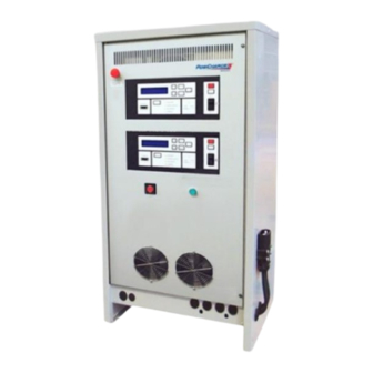
Webasto DVS100 Installation, Operation And Maintenance Manual (53 pages)
MHE Intelligent Fast Charging Systems
Brand: Webasto
|
Category: Battery Charger
|
Size: 2 MB
Table of Contents
Advertisement
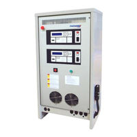
Webasto DVS100 Installation Manual (20 pages)
Brand: Webasto
|
Category: Battery Charger
|
Size: 1 MB
Table of Contents
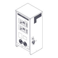
Webasto DVS100 Installation Manual (16 pages)
MHE Intelligent Fast Charging Systems
Brand: Webasto
|
Category: Battery Charger
|
Size: 0 MB
Table of Contents
Advertisement

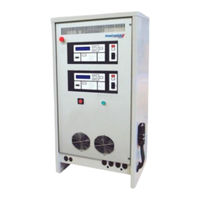
Webasto DVS100 Installation Manual (16 pages)
GSE Intelligent Fast Charging Systems
Brand: Webasto
|
Category: Battery Charger
|
Size: 1 MB