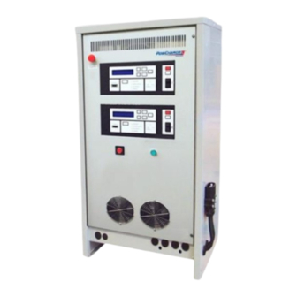
Webasto DVS100 Installation Manual
Gse intelligent fast charging systems
Hide thumbs
Also See for DVS100:
- Installation manual (20 pages) ,
- Installation manual (16 pages) ,
- Installation, operation and maintenance manual (53 pages)
Summary of Contents for Webasto DVS100
- Page 1 Installation Manual GSE Intelligent Fast Charging Systems DVS100 / DVS150 English 20182-W-76-01.docx...
- Page 2 Webasto Charging Systems, Inc. Disclaimer: this manual includes the latest information available at the time of printing. Webasto Charging Systems, Inc. Reserves the right to make changes to this manual and/or product without further notice. Changes or modifications to this product not completed by an authorized service provider could void the product warranty.
- Page 3 © 2019 Webasto Charging Systems Inc. 20182-W-76-01.docx...
-
Page 4: Table Of Contents
DVS100 / DVS150 Installation Manual IMPORTANT INFORMATION – SAVE THESE INSTRUCTIONS Table of Contents Getting Started ......................5 Safety Precautions – Read before using ..............5 2.1 Symbol usage ......................5 2.2 Technical Support ....................6 2.3 ESD Precautions ..................... 6 System Description ...................... -
Page 5: Getting Started
DVS100 / DVS150 Installation Manual IMPORTANT INFORMATION – SAVE THESE INSTRUCTIONS 1 Getting Started Before you begin, take the time to familiarize yourself with the Cautions in Section 2, and read the installation instructions in Section 4 completely before you install your new DVS. -
Page 6: Technical Support
DVS100 / DVS150 Installation Manual IMPORTANT INFORMATION – SAVE THESE INSTRUCTIONS The charging cables must be sized for the full rated current of the DVS, and inspected frequently for wear, cuts and abrasion. Do not use worn, damaged, undersized, or poorly spliced cable. -
Page 7: System Description
DVS100 / DVS150 Installation Manual IMPORTANT INFORMATION – SAVE THESE INSTRUCTIONS 3 System Description The keypad and display provide the user interface to the charger. The display constantly updates the charger and battery status, and allows access to the programming menus through the keypad. -
Page 8: Installation
DVS100 / DVS150 Installation Manual IMPORTANT INFORMATION – SAVE THESE INSTRUCTIONS Installation This section outlines the requirements and procedures for installing the DVS. Read the entire section before proceeding with installation, and make sure you have read and understood the warnings in Section 2. Installation should be completed by an experienced electrician and should conform to all relevant electrical codes. -
Page 9: Physical Installation
DVS100 / DVS150 Installation Manual IMPORTANT INFORMATION – SAVE THESE INSTRUCTIONS 4.3 Physical Installation DVS100 DVS150 DVS Weight 240kg (529lbs) 280gk (617lbs) Always use appropriate equipment for handling the unit. Use a forklift of sufficient capacity to lift the unit. - Page 10 DVS100 / DVS150 Installation Manual IMPORTANT INFORMATION – SAVE THESE INSTRUCTIONS 91.4cm (36in) MIN. 45.7cm (18 in) MIN. 45.7cm 91.4cm (18 in) (36 in) MIN. MIN. 91.4cm (36 in) MIN. 86.4cm 72.4cm (34 in) (28.5 in) MIN. MIN. CONCRETE BOLT ANCHOR 6.4cm (1/4") DIA X 12.7cm (5.0") LG...
- Page 11 DVS to prevent damage to the DVS from a moving vehicle. The square mounting holes are 6.5mm X 6.5 mm. 35,6 mm 429,3 mm 53,4 mm 585 mm Figure 4-2 Bolt Pattern for DVS100 and DVS150 Installation 20182-W-76-01.docx Webasto Charging Systems, Inc.
-
Page 12: Connecting Ac (Utility) Power
DVS100 / DVS150 Installation Manual IMPORTANT INFORMATION – SAVE THESE INSTRUCTIONS 4.4 Connecting AC (Utility) Power Prior to connecting the unit to the utility ensure that: The available grounding connection meets all state and local codes. The main circuit breaker or other “line disconnect” device is within sight of the unit and is CAUTION easily accessible to allow complete power down of the unit. -
Page 13: Table 4-2 Output Characteristics For Dvs
DVS100 / DVS150 Installation Manual IMPORTANT INFORMATION – SAVE THESE INSTRUCTIONS Table 4-2 Output Characteristics for DVS Configuration DVS100 DVS150 Max Output Power (kW) 2 X 10 kW 2 X 15 kW Max Output DC Range (Volts) 16-120V 16-130V Max Output DC Current (Amps) -
Page 14: Figure 4- 1 Ac Input Terminal Block
DVS100 / DVS150 Installation Manual IMPORTANT INFORMATION – SAVE THESE INSTRUCTIONS AC INPUT TERMINAL BLOCK TRANSFORMER TAPS TERMINAL BLOCK Figure 4- 1 AC Input Terminal Block CHASSIS GROUND CONNECTOR Figure 4- 2 Location of Chassis Ground Connector 20182-W-76-01.docx Webasto Charging Systems, Inc. -
Page 15: Dc Output Cable Installation
DVS100 / DVS150 Installation Manual IMPORTANT INFORMATION – SAVE THESE INSTRUCTIONS 4.5 DC Output Cable Installation Figure 4-3 DC Output Cable Installation To install output cable(s): 1. Install output cable(s) ensuring mounting screws and lock washers are properly installed and tightened. Recommended torque: 8.47 Nm (75 in-lbs) -
Page 16: Checklist
VERIFY AND RECORD SW VERSION CHECK UNIT IS SECURELY MOUNTED CHECK AC CIRCUIT BREAKER RATING DVS100 RATING IS 32 AAC @ 400-415VAC DVS150 RATING IS 63 AAC @ 400-415VAC DVS100 RATING IS 30 AAC @ 440VAC DVS150 RATING IS 57 AAC @ 440VAC...


Need help?
Do you have a question about the DVS100 and is the answer not in the manual?
Questions and answers