Webasto DVS100 Installation Manual
Hide thumbs
Also See for DVS100:
- Installation manual (16 pages) ,
- Installation manual (16 pages) ,
- Installation, operation and maintenance manual (53 pages)
Table of Contents
Advertisement
Quick Links
Advertisement
Table of Contents

Related Manuals for Webasto DVS100


Summary of Contents for Webasto DVS100
- Page 1 DVS100/DVS150 CAN Board Installation Guide...
-
Page 2: Table Of Contents
4.5. Powering Back on the DVS100/DVS150 Charger .................. 16 Figures Figure 1 DVS100/DVS150 Charger Decal ..................... 3 Figure 2 DVS100/DVS150 Charger Decal, Manufacturer Nameplate, and Caution Label Placements ……….4 Figure 3 Caution Label ........................... 5 5911436 A01 Webasto Charging Systems, Inc. - Page 3 Figure 8 CAN Board Connected to the 5–Volt-Direct-Current (-VDC) Supply, at Port P2, on the Channel A of DVS100/DVS150 Control Board, with the Ribbon Cable ....10 Figure 9 P101 Cable Connected from the J101 Connector on the DVS100/DVS150 CAN Board to the J2 Connector on the Channel A of DVS100/DVS150 Control Board ........
-
Page 4: Safety Precautions: Read Before Using
Indicates information about safety practices which, if not followed, may result in death or DANGER serious injury NOTE Indicates helpful information for installation or usage but does not contain personnel or equipment safety-related information 5911436 A01 Webasto Charging Systems, Inc. Page 1 of 17... -
Page 5: Document Purpose
3. CAN Board Overview 3.1. Description The CAN board is a circuit board that can be added to the DVS100/DVS150 control board. 3.2. Function The DVS CAN board sends out a CAN message on the charger’s COMM wires. If a vehicle with a BMS (Battery Management System) connects to the charger, the BMS will respond to this message and the charger will begin a charge using the IPC CAN protocol. -
Page 6: Dvs100/Dvs150 Charger Decal, Manufacturer Nameplate, And Caution Label
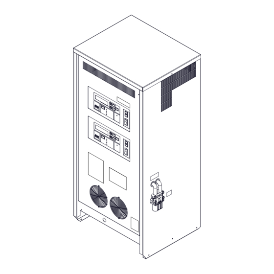
DVS-CAN Board Installation Guide DVS100/DVS150 Charger Decal, Manufacturer Nameplate, and Caution Label 3.6. An DVS100/DVS150 charger decal (sticker) (Figure 1) indicating that the DVS100/DVS150 charger is CAN compatible is adhered to the front-panel door of the charger, on the lower-middle right side, under the... -
Page 7: Figure 2 Dvs100/Dvs150 Charger Decal, Manufacturer Nameplate, And Caution Label Placements
DVS-CAN Board Installation Guide DVS100/150 CHARGER DECAL Manufacturer name plate label Caution label Figure 2 DVS100/DVS150 Charger Decal, Manufacturer Nameplate, and Caution Label Placements 5911436 A01 Webasto Charging Systems, Inc. Page 4 of 17... -
Page 8: Dvs100/Dvs150 Can Board Installation Process
The following sections walk technicians through a four-step installation process. Step 1: Updating the Charger Software Version Step 2: Powering off the DVS100/150 Charger Step 3: Installing the Board Step 4: Powering Back on the DVS100/DVS150 Charger 5911436 A01 Webasto Charging Systems, Inc. Page 5 of 17... -
Page 9: Updating The Charger Software Version
4.2.1. Power off the DVS100/DVS150 charger before installation. DANGER RISK OF SHOCK The DVS100/DVS150 charger needs to be powered off during installation. Do not restore power to the charger until the installation is completed. Failure to follow these instructions could result in shock or electrocution. -
Page 10: Installing The Can Board
(Figure 4). The X1 and P101 cables are connected to the X1 and J101 connectors, respectively, on the board (Figure 4). The DVS100/DVS150 CAN board snaps on to the mounting bracket. NOTE Ensure that the P101 cable is connected to the J101 connector, as shown in Figure 4. -
Page 11: Figure 5 Dvs100/Dvs150 Channel A Control Board Assembly
DVS-CAN Board Installation Guide 4.3.1. Loosen the two top- and bottom-right nuts from the DVS100/DVS150 control board assembly (Channel A) (Figure 5). Figure 5 DVS100/DVS150 Channel A Control Board Assembly 4.3.2. Place the DVS100/DVS150 CAN board assembly on the Channel A of DVS100/DVS150 control board assembly, over the loosened nuts, and slide the CAN board toward the control board, as and tighten the two nuts. -
Page 12: Figure 6 Can Board Assembly Mounting For Channel A
DVS-CAN Board Installation Guide Note: DIP switches shall CAN board assembly be accessible. Figure 6 CAN Board Assembly Mounting for Channel A Figure 7 DIP Switches 5911436 A01 Webasto Charging Systems, Inc. Page 9 of 17... -
Page 13: Figure 8 Can Board Connected To The 5-Volt-Direct-Current (-Vdc) Supply, At Port P2, On The Channel A Of Dvs100/Dvs150 Control Board, With The Ribbon Cable
DVS-CAN Board Installation Guide 4.3.3. Connect the DVS100/DVS150 CAN board ribbon cable connector to port P2 on the Channel A of DVS100/DVS150 control board (Figure 8). Figure 8 CAN Board Connected to the 5–Volt-Direct-Current (-VDC) Supply, at Port P2, on the Channel A of DVS100/DVS150 Control Board, with the Ribbon Cable 4.3.4. -
Page 14: Figure 10 Disconnected Bmid Connector And Bmid Cable Tied Securely To The Harness With Cable Ties
DVS-CAN Board Installation Guide 4.3.5. Disconnect the BMID connector J13(P13) from the Channel A of DVS100/DVS150 control board, and tie it, along with the attached BMID cable, securely to the harness with provided cable ties (Figure 10). Figure 10 Disconnected BMID Connector J13(P13) and BMID Cable Tied Securely to the Harness with Cable Ties For Channel A cables 4.3.6. -
Page 15: Installing The Can Board For Channel B
Figure 12 Cut BMID Wires Screwed into One Wire Nut 4.4. Installing the CAN Board for Channel B 4.4.1. Loosen the two top- and bottom-right nuts from the DVS100/DVS150 control board assembly (Channel B) (Figure 13). Figure 13 DVS100/DVS150 Channel B Control Board Assembly 4.4.2. -
Page 16: Figure 14 Can Board Assembly Mounting For Channel B
Baud Rate DIP 1 125 kbps 250 kbps CAN board assembly Note: DIP switches shall be accessible. Figure 14 CAN Board Assembly Mounting for Channel B Figure 15 DIP Switches 5911436 A01 Webasto Charging Systems, Inc. Page 13 of 17... -
Page 17: Figure 16 Can Board Connected To The 5-Volt-Direct-Current (-Vdc) Supply, At Port P2, On The Channel B Of Dvs100/Dvs150 Control Board, With The Ribbon Cable
DVS-CAN Board Installation Guide 4.4.3. Connect the DVS100/DVS150 CAN board ribbon cable connector to port P2 on the Channel B of DVS100/DVS150 control board (Figure 16). Figure 16 CAN Board Connected to the 5–Volt-Direct-Current (-VDC) Supply, at Port P2, on the Channel B of DVS100/DVS150 Control Board, with the Ribbon Cable 4.4.4. -
Page 18: Figure 18 Disconnected Bmid Connector And Bmid Cable Tied Securely To The Harness With Cable Ties
DVS-CAN Board Installation Guide 4.4.5. Disconnect the BMID connector J13(P13) from the Channel B of DVS100/DVS150 control board, and tie it, along with the attached BMID cable, securely to the harness with provided cable ties (Figure 18). Figure 18 Disconnected BMID Connector J13(P13) and BMID Cable Tied Securely to the Harness with Cable Ties For Channel B 4.4.6. -
Page 19: Powering Back On The Dvs100/Dvs150 Charger
Figure 20 Cut BMID Wires Screwed into One Wire Nut Step 4 4.5. Powering Back on the DVS100/DVS150 Charger 4.5.1. Power back on the DVS100/DVS150 charger after installation. 5911436 A01 Webasto Charging Systems, Inc. Page 16 of 17... - Page 20 DVS-CAN Board Installation Guide Webasto Charging Systems, Inc. 1333 S. Mayflower Ave., Ste 100 Monrovia, CA 91016, USA Corporate headquarters: Friedrichshafener Str. 9 82205 Gilching Germany 5911436 A01 Webasto Charging Systems, Inc. Page 17 of 17...
Need help?
Do you have a question about the DVS100 and is the answer not in the manual?
Questions and answers