Webasto DVS100 Installation Manual
Mhe intelligent fast charging systems
Hide thumbs
Also See for DVS100:
- Installation manual (20 pages) ,
- Installation manual (16 pages) ,
- Installation, operation and maintenance manual (53 pages)

Related Manuals for Webasto DVS100


Summary of Contents for Webasto DVS100
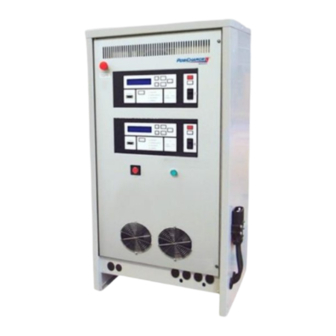
- Page 1 Installation Manual MHE Intelligent Fast Charging Systems DVS100/DVS150 CEC North America 12284-W-76-CEC-01 Webasto Charging Systems, Inc.
- Page 2 Webasto Charging Systems, Inc. Disclaimer: this manual includes the latest information available at the time of printing. Webasto Charging Systems, Inc. Reserves the right to make changes to this manual and/or product without further notice. Changes or modifications to this product not completed by an authorized service provider could void the product warranty.
-
Page 3: Table Of Contents
Safety Precautions – Read before using ......................4 Symbol usage ............................... 4 Cautions and Warnings ..........................4 Technical Support............................5 List of Webasto-Provided Equipment ......................5 ESD Precautions ............................6 System Description ............................6 Installation ................................6 Preparation ..............................6 Equipment Access ............................ -
Page 4: Getting Started
Only qualified service personnel may remove the front or back panels on the DVS. There are no user serviceable parts inside. Refer all servicing to qualified service personnel. Opening the system or attempted installation or repair by other than qualified service personnel voids the warranty. 12284-W-76-CEC-01 Webasto Charging Systems, Inc. -
Page 5: Technical Support
• Follow the National Electrical Code (NEC) and local codes. NEC and local codes take precedence. If any instructions in this manual conflict with NEC or local codes, contact Webasto Charging Systems, Inc. for further information. Technical Support This manual is intended to provide an authorized, fully trained installation technician with the information and guidance necessary to safely install the DVS equipment. -
Page 6: Esd Precautions
The DVS is provided fully assembled on a shipping pallet. It is surrounded by a protective shipping box. Remove the packaging and any other shipping materials prior to installation. The following equipment is provided with each system: 12284-W-76-CEC-01 Webasto Charging Systems, Inc. -
Page 7: Equipment Access
Use copper conductors only. • Minimum ground wire size is listed. Refer to local electrical codes for reference. 4.3.5 Hardware Manufacturer does not supply all external mounting hardware. User-supplied hardware may be needed to complete the installation. 12284-W-76-CEC-01 Webasto Charging Systems, Inc. -
Page 8: Physical Installation
Maintain a minimum of 18” of clearance on the sides of the unit for proper ventilation. • Maintain 36” minimum clearance on front and back for servicing as required by local codes. • Do not install unit where it will be exposed to direct sunlight. 12284-W-76-CEC-01 Webasto Charging Systems, Inc. -
Page 9: Figure 4-1 Dvs-100 And Dvs-150 Installation
OR WALKWAYS FOR WATER FLOOD CONTROL. C. PAD SIZE MINIMUM FOR A SINGLE CHARGER 86.4cm (34") X 72.4cm (28.5") CONCRETE 3000 PSI MIN D. CONCRFETE PAD REQUIRED ONLY FOR WATER FLOOD CONTROL Figure 4-1 DVS-100 and DVS-150 Installation 12284-W-76-CEC-01 Webasto Charging Systems, Inc. -
Page 10: Figure 4-2 Bolt Pattern For Dvs-100 And Dvs-150 Installation (Dimensions In Inches)
Figure 4-2 Bolt Pattern for DVS-100 and DVS-150 Installation (Dimensions in Inches) 12284-W-76-CEC-01 Webasto Charging Systems, Inc. -
Page 11: Connecting Ac (Utility) Power
Minimum Grounding Conductor Size (AWG) Minimum Input Wire Terminal Torque (in-lb) Minimum Ground Wire 35-44 35-44 35-44 35-44 Terminal Torque (in-lb) Output Cable Connector 320 Anderson Euro 320 Anderson Euro Reference National Electrical Code. ANSI/NFPA 70.1999 12284-W-76-CEC-01 Webasto Charging Systems, Inc. -
Page 12: Table 4-2 Output Characteristics For Dvs
NOTE: The grounding wire should have insulation that is green or green with yellow stripe. 6. Close the front door prior to switching on the utility power. WARNING ENSURE GOOD ELECTRICAL CONNECTION BY TIGHTENING ALL THE SCREWS PROPERLY 12284-W-76-CEC-01 Webasto Charging Systems, Inc. -
Page 13: Figure 4-3 Dvs-100 And Dvs-150 Location Of Transformer Taps Terminal Block
AC INPUT TERMINAL BLOCK TRANSFORMER TAPS TERMINAL BLOCK Figure 4-3 DVS-100 and DVS-150 Location of Transformer Taps Terminal Block CHASSIS GROUND CONNECTOR Figure 4-4 DVS-100 and DVS150 Location of Chassis Ground Connector 12284-W-76-CEC-01 Webasto Charging Systems, Inc. -
Page 14: Figure 4-5 Dual Voltage Systems (480/600Vac) - Location Of Auxiliary Transformer Terminal Block
Figure 4-5 Dual Voltage Systems (480/600VAC) - Location of Auxiliary Transformer Terminal Block Note: If the charger has an ADK transformer, the blue input wire stays on the 480V. 12284-W-76-CEC-01 Webasto Charging Systems, Inc. -
Page 15: Dc Output Cable Installation
2. A proper cable management system is required to relieve stress on the output connector mounting hardware. Note: 1) Do not remove connector key(s) from the connector. 2) Minimum bend radii of 3.5 in are required for the output cables. 12284-W-76-CEC-01 Webasto Charging Systems, Inc. -
Page 16: Checklist
VERIFY AND RECORD SW VERSION CHECK UNIT IS SECURELY MOUNTED CHECK AC CIRCUIT BREAKER RATING DVS100 RATING IS 40 AAC @ 480VAC DVS100 RATING IS 30 AAC @ 600VAC DVS150 RATING IS 50 AAC @ 480VAC DVS150 RATING IS 40 AAC @ 600VAC...
Need help?
Do you have a question about the DVS100 and is the answer not in the manual?
Questions and answers