Sign In
Upload
Manuals
Brands
Unipulse Manuals
Accessories
F701-P
Unipulse F701-P Manuals
Manuals and User Guides for Unipulse F701-P. We have
1
Unipulse F701-P manual available for free PDF download: Operation Manual
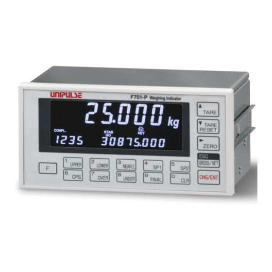
Unipulse F701-P Operation Manual (116 pages)
Brand:
Unipulse
| Category:
Accessories
| Size: 4.59 MB
Table of Contents
Table of Contents
7
Outline
12
Contents of the Package
12
About Connectable Devices
12
Appearance Description
13
Front Panel
13
Rear Panel
17
Connection
18
Load Cell Connection
19
6-Wire Connection
19
4-Wire Connection
20
Connecting Load Cells in Parallel
21
Sensors Cable
21
Connection of the Load Cell, Power Input Terminal,Rs-485 and External Input/Output Signal Terminal Blocks
22
Connection of the Protective Ground
23
Setting Method
24
Setting Procedure
24
How to Designate a Setting Mode no
24
How to Register a Setting Value
25
Setting Modes
28
Setting Mode 0
28
Setting Mode 1
28
Setting Mode 2
30
Setting Mode 3
30
Setting Mode 4
32
Setting Mode 5
33
Calibration
34
Span Calibration
34
Span Calibration Procedure
35
Preparation before Calibration
36
LOCK Release
36
Unit Display (Setting Mode 4-5)
36
Decimal Place (Setting Mode 4-5)
36
Capacity (Setting Mode 4-2)
37
Min Scale Division (Setting Mode 4-3)
37
Balance Weight Value (Setting Mode 4-1)
37
Gravitational Acceleration (Setting Mode 4-6)
37
1/4 Scale Division (Setting Mode 4-5)
38
Zero Calibration
39
Span Calibration (Setting Mode 9-1)
41
Function Settings
42
Display Update Rate (Setting Mode 4-5)
42
Subdisplay Selection (Setting Mode 4-5)
42
Digital Low Pass Filter (Setting Mode 2-1)
42
Moving Average Filter (Setting Mode 2-2)
43
Filter in Stable Condition (Setting Mode 1-5)
43
Motion Detection(MD) (Setting Mode 1-5, 2-3)
44
Setting of Motion Detection Parameters
45
Zero Tracking(ZT) (Setting Mode 2-4, 2-5)
45
Digital Zero(DZ)
46
Digital Zero Clear
46
5-10.DZ Regulation Value (Setting Mode 4-4)
46
5-11.Gross Weight Display/Net Weight Display
46
5-12.One-Touch Tare Subtraction (TARE)
47
5-13.One-Touch Tare Subtraction Reset
47
5-14.Digital Tare Subtraction (Preset Tare Weight)
47
Preset Tare Weight (Setting Mode 1-5)
47
Tare Setting (Setting Mode 1-8)
48
5-15.Tare Weight Display (Setting Mode 1-9)
48
5-16.Key Invalid (Setting Mode 3-5)
48
Weighing Setting and Operations
49
Comparison Mode (Setting Mode 1-4 Weighing Function 1)
49
Near Zero Comparison
49
Upper/Lower Limit Comparison Mode
50
Upper/Lower Limit Comparison
50
Over/Under Comparison Mode
52
Discharging Control Mode
54
Discharging Control
54
About Accumulation
57
Total Comparison Selection/Total Limit/Count Limit
57
Accumulation Clear
57
System-Related Settings and Operations
58
LOCK (Soft)
58
Passwaord
58
Self-Check
58
External Input/Output Signals (Control Connector)
59
Connector Pin Assignments
59
External Control Equipment Connection
60
Equivalent Circuit and Example Connection, When Specify the Sink Type
60
Equivalent Circuit and Example Connection, When Specify the Source Type
61
External Input Signals
62
Gross/Net Switch (G/N) <Edge Input
62
Digital Zero (D/Z ON) <Edge Input
62
Tare Subtraction (TARE ON) <Edge Input
62
Tare Subtraction Reset (TARE OFF) <Edge Input
62
Accumulation Clear <Edge Input
63
HOLD <Level Input
63
JUDGE <Level Input
63
External Output Signals
63
When Comparison Mode 0 (Upper/Lower Limit Comparison Mode) Is Set
63
When Comparison Mode 1 (Over/Under Comparison Mode) Is Set
64
When Comparison Mode 2 (Discharging Control Mode) Is Set
64
Stable
64
Weight Error
64
Total Limit
64
Interface
65
Communication Specifications
65
Standards
65
Connection
66
Two-Wire Type (Point to Point)
66
Two-Wire Type (Multi Point)
66
RS-485-Related Setting Values
67
I/F Setting
67
ID/ Slave Address for MODBUS-RTU
67
Communication Type
67
Communication Type
68
UNI-Format Commands
69
Setting Value Communication Formats
74
UNI-Format (Continuous, Auto)
75
Modbus-RTU
76
Data Address
94
About Data
96
10Specifications
101
10-1.Specifications
101
Analog Section
101
Display Section
101
Setting Section
102
External Signals
102
Interface
103
General Performance
103
Accessories
103
10-2.Dimensions
104
Mounting on a Panel
104
Packing Installation
105
10-3.Block Diagram
107
11Supplements
108
11-1.List of Setting Values
108
Setting Mode 0
108
Setting Mode 1
108
Setting Mode 2
109
Setting Mode 3
109
Setting Mode 4
109
Setting Mode 5
110
Setting Mode 9
110
11-2.Over Scale/Error Display
111
Over Scale Display
111
Calibration Error Display
111
11-3.Troubleshooting
112
Over Scale Display
112
Calibration Error Display
113
Checksum Error Display
115
F-RAM Check Error Display
115
Advertisement
Advertisement
Related Products
Unipulse F701-C
Unipulse F371
Unipulse F701
Unipulse F701+
Unipulse F340A
Unipulse f395
Unipulse DeviceNet F388A
Unipulse F600AT
Unipulse F130
Unipulse F805AT-BC
Unipulse Categories
Measuring Instruments
Touch Panel
Controller
Monitor
Accessories
More Unipulse Manuals
Login
Sign In
OR
Sign in with Facebook
Sign in with Google
Upload manual
Upload from disk
Upload from URL