Table of Contents
Advertisement
Quick Links
Advertisement
Table of Contents

Subscribe to Our Youtube Channel
Related Manuals for Unipulse F701-P


Summary of Contents for Unipulse F701-P
- Page 1 F701-P WEIGHING INDICATOR OPERATION MANUAL 01AUG2020REV.1.07...
- Page 2 Installation, maintenance and inspection of the F701-P should be performed by personnel having technical knowledge of electricity. In order to have an F701-P Weighing Indicator used safely, notes I would like you to surely follow divide into " " and "...
- Page 3 - Use greatly impacting human lives and assets, such as medical devices, transport devices entertainment devices, and safety devices. Warning on installation ● Do not disassemble, repair, or modify the F701-P. Doing so may cause a fire or an electric shock. ● Do not install in the following environments.
- Page 4 ● For turning on/off the power, be sure to keep intervals of 5 seconds or more. ● After power-on, make sure to warm up the F701-P for at least 30 minutes or more before use. ● If the F701-P is not used by the specified method, its protective performance may be impaired.
- Page 5 Caution during transportation ● When the F701-P is shipped, spacers made of corrugated cardboard are used as cushioning materials. Though it is factory-designed so that shocks can sufficiently be absorbed, breakage may result if shocks are applied when the spacers are reused for transportation.
- Page 6 If you find any damage on the product or lack of contents, please contact the department of Unipulse or our agency where you purchased the product with having kept the state as it is.
-
Page 7: Table Of Contents
Contents Contents Contents 1 OUTLINE ........... . 1 1-1. - Page 8 Contents Contents ■ 1/4 scale division (setting mode 4-5) ........27 4-4.
- Page 9 Contents Contents 7 SYSTEM-RELATED SETTINGS AND OPERATIONS ....47 7-1. LOCK (soft)............47 7-2.
- Page 10 Contents Contents 10-1.Specifications ............90 ■...
- Page 11 Contents Contents M E M O...
-
Page 12: Outline
1 OUTLINE OUTLINE Chapter 1-1. Contents of the package The packaging box contains the following. Make sure to check them before use. F701-P body ・・・1 F701-P operation manual ・・・1 Packing・・・1 AC input cord・・・1 Jumper wire・・・2 Terminating resistance・・・1 1-2. About connectable devices... -
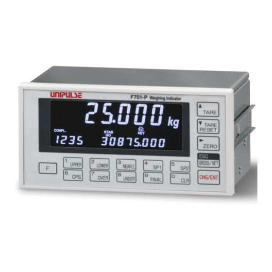
Page 13: Appearance Description
1 OUTLINE 1-3. Appearance description Chapter ■Front panel ①Main display ③Unit display ④Status display ②Subdisplay ⑥Function keys ⑤Setting key ①Main display The following three types of displays will appear. (1) Weight value display Gross weight or net weight is displayed. In the case of a calibration error, the error and weight value are displayed alternately. (2) Over scale/error display Over scale and other errors are displayed. - Page 14 1 OUTLINE (4) Final Chapter Final value (5) None Accumulation count An accumulated count is displayed. No more accumulations are made after "9999", which cannot be counted up any more. It is initialized to "0" by performing Accumulation Clear. Accumulation value An accumulated value is displayed.
- Page 15 1 OUTLINE Lights when tare subtraction is performed. Chapter Blinks when the tare weight is displayed by setting mode 1-9 "tare display." Lights when the net weight is displayed. Goes out when the gross weight is displayed. Lights when the gross weight is displayed. Goes out when the net weight is displayed.
- Page 16 1 OUTLINE < TARE RESET > Chapter Tare subtraction is reset by this key. However, the tare weight by digital tare subtraction (preset tare weight) is not reset. < ▼ > While a setting item is displayed, this key functions to change the selected item number.
-
Page 17: Rear Panel
1 OUTLINE ■Rear panel Chapter ②Protective ground ①AC power input terminal block ③Frame ground ④External input/output signal ⑥Load cell terminal block terminal block ⑤RS-485 terminal block ①AC power input terminal block Connect AC power code. The input voltage is 100V - 240V AC. The applicable terminal block is JITE-manufactured PTB750B-04-2-3P-3. -
Page 18: Connection
2 CONNECTION CONNECTION Precautions about connection to the signal input/output terminal block are given below. Chapter The precautions described here are important for safety. Please properly understand the descriptions before connection. WARNING - Do not connect a commercial power source directly to the signal input/output terminals. -
Page 19: Load Cell Connection
2 CONNECTION 2-1. Load cell connection The applied voltage and maximum current of the F701-P, to which up to six 350-ohm load cells can be connected in parallel, are 5V and 90mA, respectively. Chapter Load cell terminal block Load cell terminal block pin assignments Pin No. -
Page 20: 4-Wire Connection
These jumpers MUST be connected. CAUTION - The load cell excitation voltage of the F701-P is 5V. Heating or breakage may occur unless the load cells maximum excitation voltage is 5V or more. - When using the F701-P with the four-wire load cell connected, be sure to connect +EXC and +S, and -EXC and -S. -
Page 21: Connecting Load Cells In Parallel
2 CONNECTION ■Connecting load cells in parallel In some industrial weighing apparatus, two or more load cells may be connected in parallel to form a hopper scale or track scale. The manner of connection is shown below. Parallel connection can simply be made by using the optionally available B410 (summing box for 4-point multi load cell). -
Page 22: Connection Of The Load Cell, Power Input Terminal,Rs-485 And External Input/Output Signal Terminal Blocks
5mm, and twist the end to such an extent that it will not become loose. Remove the terminal block from the F701-P body with a strong pull. Loosen the screw with a screwdriver to open the hole. A Phillips screwdriver with a shaft diameter of 3 - 3.5mm #1 is recommendable. -
Page 23: Connection Of The Protective Ground
AC, 7A. For use at voltages exceeding the rating and for overseas use, have a separate AC cable prepared. - Since the F701-P has no power switch, install a breaker. - Be sure to ground the protective ground terminal to prevent electric shocks. -
Page 24: Setting Method
3 SETTING METHOD SETTING METHOD 3-1. Setting procedure Change settings in the order of "selection of a setting mode"→"selection of a setting item"→"registration of a setting value." Chapter ■How to designate a setting mode No. In the text, how to designate a setting mode No. is described as follows: Example) For designating setting mode 4 →... -
Page 25: How To Register A Setting Value
3 SETTING METHOD Press the key. The selected setting mode No. and weight value are displayed (Setting mode No. display). Setting mode No. Current weight value Point Pressing the key when a setting mode No. is displayed restores the usual Chapter display (setting mode 0). - Page 26 3 SETTING METHOD Upon input of a proper setting value, press the key to register the setting value. The display returns to the setting mode No. display. Setting mode No. Current weight value Chapter Example 2) For turning off 1/4 scale division (setting by choice) →...
- Page 27 3 SETTING METHOD Make a choice among the alternatives. (Press the key because 1/4 scale division should be turned off.) Since the blinking number moves to a lower-order digit each time the key is pressed, you can redo the setting as many times as you want. 1/4 scale division Setting item No.
-
Page 28: Setting Modes
3 SETTING METHOD 3-2. Setting modes ■Setting mode 0 Setting mode 0 relates to weighing comparison. - Upper limit (0 - 99999) - Lower limit Chapter (0 - 99999) - Near zero (0 - 99999) - Set point 1 (0 - 99999) - Set point 2 (0 - 99999) - Compensation... - Page 29 3 SETTING METHOD - Complete output time (hold time) (0 - 9.9) - Weighing function 1 Comparison mode Auto hold mode 0: Invalid 0: Uppert/Lower limit comparison Chapter 1: Valid mode 1: Over/Under comparison mode Near zero comparison mode 2: Discharging control mode 0: Near zero signal ON when gross weight ≦...
-
Page 30: Setting Mode 2
3 SETTING METHOD - Tare setting (0 - 99999) - Tare display (-99999 - 99999) * Display only ■Setting mode 2 Chapter Setting mode 2 relates to internal operations. - Digital low pass filter 0: 1.5Hz 3: 3Hz 1: 2Hz 4: 4Hz 2: 2.5Hz 5: 5Hz - Moving average filter... - Page 31 3 SETTING METHOD - Total limit (under 5) (0 - 99999) - Count limit (0 - 9999) - Key invalid Chapter [TARE] key [GROSS/NET] key 0: Invalid 0: Invalid 1: Valid 1: Valid [TARE RESET] key [ZERO] key 0: Invalid 0: Invalid 1: Valid 1: Valid - LOCK...
-
Page 32: Setting Mode 4
3 SETTING METHOD ■Setting mode 4 Setting mode 4 relates to calibration. - Balance weight value (0 - 99999) - Capacity (1 - 99999) Chapter - Min scale division (1 - 50) - DZ regulation value (0 - 9999) - Display selection Decimal place Subdisplay selection 0: None... -
Page 33: Setting Mode 5
3 SETTING METHOD ■Setting mode 5 Setting mode 5 relates to I/F. - RS-485 I/F setting Baud rate Terminator (effective at only UNI-Format) 0: 1200bps 0: CR 1: 2400bps 1: CR+LF 2: 4800bps Chapter 3: 9600bps Stop bit 4: 19200bps 0: 1bit 5: 38400bps 1: 2bit The length of character... -
Page 34: Calibration
4-1. Span calibration Calibration is performed for matching the F701-P to a load cell. For example, it is work to adjust so that the F701-P accurately displays 100.00kg when an actual load (or weight) of 100kg is applied to the load cell (balance section) of the weighing apparatus to which the F701-P is connected. This operation is called Span Calibration. -
Page 35: Span Calibration Procedure
4 CALIBRATION 4-2. Span calibration procedure Follow the steps below to perform Span Calibration. Release the setting value LOCK that disables calibration. Setting value LOCK release (Setting mode 3-6) Set the unit for display. Unit display (Setting mode 4-5) Set the decimal place. Decimal place (Setting mode 4-5) Set the capacity for use as a scale. -
Page 36: Preparation Before Calibration
Select the decimal place from 0: None/1: 0.0/2: 0.00/3: 0.000. Display selection Decimal place 0: None 1: 0.0 2: 0.00 3: 0.000 Point In the F701-P, the decimal place is fixed for all other than weight-related data. * It cannot be changed. -
Page 37: Capacity (Setting Mode 4-2)
4 CALIBRATION ■Capacity (setting mode 4-2) Set the maximum value (capacity) for use as a scale. If the value set here is exceeded by 9 scale divisions, over scale display " " will appear. (Input range/1 - 99999) ■Min scale division (setting mode 4-3) Set the minimum unit (scale interval) for weighing. -
Page 38: 1/4 Scale Division (Setting Mode 4-5)
4 CALIBRATION China's gravitational accelerations Region Acceleration (G) Region Acceleration (G) Region Acceleration (G) Beijing 9.8155m/s Wuhan 9.7936m/s Kaifeng 9.7966m/s Tianjin 9.8011m/s Hohhot 9.7986m/s Nanchang 9.7920m/s Tangshan 9.8016m/s Jilin 9.8048m/s Guangzhou 9.7883m/s Shijiazhuang 9.7997m/s Changchun 9.8048m/s Tsingtau 9.7985m/s Kunming 9.7836m/s Xi'an 9.7944m/s Nanjing 9.7948m/s... -
Page 39: Zero Calibration
4 CALIBRATION 4-4. Zero calibration Register the initial zero point. - Check around the load cell (scale) for unwanted loads such that foreign matter is placed or there is contact with peripheral equipment. - Check that " " is on. (When the indicated value is not stable, accurate calibration cannot be performed.) Select setting mode 9 (calibration mode). - Page 40 4 CALIBRATION (calibration error) The initial dead load exceeds the zero adjustment range. Connect a resistor of an appropriate value between the +EXC and -SIG terminals of the load cell, shift the zero point, and then perform zero calibration again. Point For reference, relationships between connected resistance values and input signals are listed below.
-
Page 41: Span Calibration (Setting Mode 9-1)
4 CALIBRATION 4-5. Span calibration (setting mode 9-1) Put a balance weight on the load cell (scale), and register the span (gain). - Put a balance weight of the weight set by balance weight value on the load cell (scale). (Calibration with a balance weight of 50% or more of the capacity is advantageous in terms of linearity, etc.) - Check for unwanted loads as in the case of zero calibration. -
Page 42: Function Settings
5 FUNCTION SETTINGS FUNCTION SETTINGS 5-1. Display update rate (setting mode 4-5) Set the number of updates of the indicated value per second. What is selected here is only the display update rate. The internal A/D conversion rate and CPU processing speed stay unchanged. The display update rate can be selected from 1 time/sec, 2 times/sec, 5 times/sec, 10 times/sec, and 20 times/sec. -
Page 43: Moving Average Filter (Setting Mode 2-2)
Select whether or not to insert it. Definition of stability is given by "5-6.Motion detection(MD) (setting mode 1-5, 2-3)" on page 33. When Stable is OFF or the filter in stable condition Chapter F701-P is not inserted. Digital Moving Digital... -
Page 44: Motion Detection(Md) (Setting Mode 1-5, 2-3)
5 FUNCTION SETTINGS 5-6. Motion detection(MD) (setting mode 1-5, 2-3) Set the parameters to detect that the indicated value is stable. When the variation width of the weight value becomes a set width or less and the state continues for a set period or more, the weight value is assumed to be stable, and the stable signal turns on. There are two modes of motion detection: stable mode and checker mode. -
Page 45: Setting Of Motion Detection Parameters
5 FUNCTION SETTINGS ■Setting of motion detection parameters - Motion detection mode (setting mode 1-5) elect the stable condition from stable mode and checker mode. Weighing function 2 Stable detection mode 0: Stable mode 1: Checker mode - Motion detection period (setting mode 2-3) Set the period to judge that the weight value is stable. -
Page 46: Digital Zero(Dz)
" blinks to give an alarm. (Input range/0 - 9999) 5-11. Gross weight display/net weight display The F701-P can display gross weight or net weight selectively. Switch between gross weight display and net weight display with the key. Each time the key is pressed, switching is performed between gross weight display and net weight display alternately. -
Page 47: 5-12.One-Touch Tare Subtraction (Tare)
5 FUNCTION SETTINGS * For one-touch tare subtraction, see "5-12.One-touch tare subtraction (TARE)" on page 36. * For digital tare subtraction, see "5-14.Digital tare subtraction (preset tare weight)" on page 36. 5-12. One-touch tare subtraction (TARE) This function makes the gross weight and tare weight equal to zero the net weight. Press the key. -
Page 48: Tare Setting (Setting Mode 1-8)
5 FUNCTION SETTINGS ■Tare setting (setting mode 1-8) A value exceeding the capacity or a scale interval falling below the min scale division cannot be input. (Input range/0 - 99999) Point One-touch tare subtraction and digital tare subtraction (preset tare weight) work independently. -
Page 49: Weighing Setting And Operations
WEIGHING SETTING AND OPERATIONS 6-1. Comparison mode (setting mode 1-4 weighing function 1) On the F701-P, three weighing methods can be selected by comparison mode. Select from three comparison modes. Weighing function 1 Comparison mode 0: Upper/Lower limit comparison mode... -
Page 50: Upper/Lower Limit Comparison Mode
6 WEIGHING SETTING AND OPERATIONS 6-3. Upper/lower limit comparison mode The upper limit and lower limit are set, with respect to each of which weight values are compared in this mode. This is convenient to simple checkers. ■Upper/lower limit comparison Set the upper limit and lower limit as desired, and set the weight to be compared by comparison weight value. - Page 51 6 WEIGHING SETTING AND OPERATIONS - Time chart in upper/lower limit comparison mode Weight value Upper Limit Lower Limit Near zero Time Stable (STAB) Near zero (NZ) Chapter HOLD Hold time t1 : Determine the stable condition by stable detection mode (weighing function 2 in setting mode 1-5) and motion detection (setting mode 2-3).
-
Page 52: Over/Under Comparison Mode
6 WEIGHING SETTING AND OPERATIONS 6-4. Over/under comparison mode Over and Under based on the target value are set, with respect to each of which weight values are compared in this mode. This is convenient to simple checkers. ■Over/under comparison mode Set Target, Over, and Under as desired, and set the weight to be compared by comparison weight value. - Page 53 6 WEIGHING SETTING AND OPERATIONS - Time chart in over/under comparison mode Weight value Target value + Over Target value Target value-Under Near zero Time Stable (STAB) Near zero (NZ) Chapter HOLD Hold time t1 : Determine the stable condition by stable detection mode (weighing function 2 in setting mode 1-5) and motion detection (setting mode 2-3).
-
Page 54: Discharging Control Mode
6 WEIGHING SETTING AND OPERATIONS 6-5. Discharging control mode A fixed amount is accurately discharged from a tank like a hopper in this mode. In this mode, after completion of the previous weighing, when the weight drops below 25% of the fixed amount, the state is judged as the next weighing is possible. - Page 55 6 WEIGHING SETTING AND OPERATIONS - Comparison inhibit time (setting mode 1-1) Input range/0.00 - 9.99 (sec.) In discharging control mode, comparison can be inhibited for a fixed time to prevent inappropriate control operation by mechanical vibrations associated with valve opening and closing. Comparison inhibit time works from when the weight value reaches (final - set point 1), (final - set point 2).
- Page 56 6 WEIGHING SETTING AND OPERATIONS - Time chart in discharging control mode Final Final-Compensation Final-Set point 2 Final-Set point 1 Near zero Time Stable (STAB) Near zero (NZ) TARE Chapter Comparison inhibit timer Comparison inhibit time t1 Comparison inhibit time t1 Judging timer Judging time t2 Complete...
-
Page 57: About Accumulation
6 WEIGHING SETTING AND OPERATIONS 6-6. About accumulation The timing which makes a weight value accumulate is as follows by comparison mode (setting mode 1-4). - Upper/lower limit comparison mode / over/under comparison mode Accumulation is performed when the near zero signal is OFF and stable signal is ON. After the last completion of measurement, when near zero turns ON, it is judged as a state measurable next time. -
Page 58: System-Related Settings And Operations
7 SYSTEM-RELATED SETTINGS AND OPERATIONS SYSTEM-RELATED SETTINGS AND OPERATIONS 7-1. LOCK (soft) This lock is intended to prevent misoperation. For setting values effective on LOCK (soft), see"11- 1.List of setting values" on page 97. Select from 0:OFF or 1:ON. LOCK LOCK1 LOCK2 0: OFF 0: OFF... -
Page 59: External Input/Output Signals (Control Connector)
8 EXTERNAL INPUT/OUTPUT SIGNALS (CONTROL CONNECTOR) EXTERNAL INPUT/OUTPUT SIGNALS (CONTROL CONNECTOR) The input/output and internal circuits are electrically insulated by photocoupler. There is a need to prepare external 24V DC (power supply for external input/output signal circuit) separately. 8-1. Connector pin assignments External output 1-4 External input 1-4 Power supply on the outside... -
Page 60: External Control Equipment Connection
External input and output signals can only be connected to either the sink type or source type. Specify at order-time. ■Equivalent circuit and example connection, when specify the sink type - Output The signal output circuit is photocoupler isolated open-collector output (current sink type). F701-P PLC, etc. +24V +24V Sink type DC24V+... -
Page 61: Equivalent Circuit And Example Connection, When Specify The Source Type
8 EXTERNAL INPUT/OUTPUT SIGNALS (CONTROL CONNECTOR) ■Equivalent circuit and example connection, when specify the source type - Output The signal output circuit is photocoupler isolated output (current source type). F701-P PLC, etc. +24V Source type DC24V+ Input Output OUT1 - OUT4... -
Page 62: External Input Signals
8 EXTERNAL INPUT/OUTPUT SIGNALS (CONTROL CONNECTOR) 8-3. External input signals ■Gross/net switch (G/N) <edge input> Net weight display is brought about at the ON edge. Gross weight display is brought about at the OFF edge. Net weight display Gross weight display ■Digital zero (D/Z ON) <edge input>... -
Page 63: Accumulation Clear
8 EXTERNAL INPUT/OUTPUT SIGNALS (CONTROL CONNECTOR) ■Accumulation clear <edge input> Accumulation data is cleared at the ON edge. The same operation is also performed with the key. → Pulse width 50msec or more ■HOLD <level input> While this is ON, the weight value and comparison are held. This input terminal serves as JUDGE according to setting. -
Page 64: When Comparison Mode 1 (Over/Under Comparison Mode) Is Set
8 EXTERNAL INPUT/OUTPUT SIGNALS (CONTROL CONNECTOR) ■When comparison mode 1 (over/under comparison mode) is set HI, GO, LO Each signal turns on under the following condition. - HI: Weight value > (Target value + Over) - GO: (Target value - Under) ≦ Weight value ≦ (Target value + Over) - LO: Weight value <... -
Page 65: Interface
9 RS-485 INTERFACE RS-485 INTERFACE The RS-485 interface is intended to read the indicated value and status of the F701-P and read/write setting values with the F701-P. It is convenient for processing of control, compilation, recording, etc., as the F701-P is connected to a PLC, programmable display, etc. -
Page 66: Connection
- The SG terminal is a ground terminal used in circuits (to protect the circuits). If the F701-P body and the equipment on the other end of the connection are class-D-grounded, usually there is no need to use the SG terminal. -
Page 67: Rs-485-Related Setting Values
9 RS-485 INTERFACE 9-3. RS-485-related setting values ■RS-485 I/F setting Set the RS-485 port of this device. (Setting mode 5-1) * If the communication type is Modbus-RTU, set as length of character: 8 bits and stop bit: 1 bit (stop bit: 2 bits if the parity bit is none). RS-485 I/F setting Baud rate Terminator... -
Page 68: Communication Type
9 RS-485 INTERFACE ■Communication type - Communication type 0 (mode=0: Command) Communication is performed with the command from the host computer. (Weight data is not transmitted automatically.) Terminator is selectable from CR or CR + LF. - Communication type 1 (mode=2: Continuous, format=0: Gross weight) Gross weight is transmitted continuously. -
Page 69: Uni-Format Commands
■UNI-Format commands ■Command communication formats - Read the gross weight (sign, 5-digit weight, decimal point) Chapter IDNo. Host 1 0 0 + F701-P IDNo. - Read the net weight (sign, 5-digit weight, decimal point) IDNo. Host 1 0 0 + F701-P IDNo. - Page 70 9 RS-485 INTERFACE - Read status 1 (8-digit) IDNo. Host F701-P IDNo. HOLD LOCK 0: OFF 0: LOCK1 and LOCK2 OFF 1: ON 1: LOCK1 ON 2: LOCK2 ON 3: LOCK1 and LOCK2 ON 0: OFF Total limit 1: ON 0: OFF...
- Page 71 * For setting value No., see "■Setting value communication formats" on page 63. - Zero calibration F701-P 0 CR F701-P IDNo. Calibration in progress IDNo. Normal end 2 - 9: Error (same as the F701-P error display No.) Calibration disabled by LOCK2 Calibration in progress...
- Page 72 IDNo. Calibration in progress IDNo. Normal end 2 - 9: Error (same as the F701-P error display No.) Calibration disabled by LOCK2 Calibration in progress Attention Zero calibration/span calibration Before sending this command, set the capacity, min scale division, balance weight value, etc.
- Page 73 * The RJ buffer (storing data for the RJ command) is also cleared. Chapter Attention - After receiving a response from the F701-P, keep an interval of 5mSec or more until sending the next command from the host. 5mSec or more Host ・...
-
Page 74: Setting Value Communication Formats
9 RS-485 INTERFACE ■Setting value communication formats These are used for reading and writing setting values. Upper limit CR LF (When LOCK1 can not write in) Lower limit CR LF (When LOCK1 can not write in) Near zero CR LF (When LOCK1 can not write in) Set point 1 CR LF (When LOCK1 can not write in) -
Page 75: Uni-Format (Continuous, Auto)
9 RS-485 INTERFACE Total comparison CR LF (When LOCK1 can not write in) selection Total limit (high 4) CR LF (When LOCK1 can not write in) Total limit (under 5) CR LF (When LOCK1 can not write in) Count limit CR LF (When LOCK1 can not write in) Key invalid CR LF... -
Page 76: Modbus-Rtu
F : Comparison OFF Priority : C, F > 3 > 2 > 1 > 0 Priority : N, F > (H or L) > G * If two or more F701-P are connected, do not specify continuous mode. Chapter ■Modbus-RTU ■Transmission delay time (setting mode 5-4) - Page 77 9 RS-485 INTERFACE ■Function codes for Modbus Function codes are explained in detail. In this chapter, function fields and data fields varying by function codes are explained. Each actual message frame consists of an address field, function field, data field, and error check field, which are transmitted in this order.
- Page 78 Keep in mind that the relative address for reading the digital zero value is 0x04. In cases less than 8 bits, the remainder bits become "0". * The F701-P response (coil state) is always "0" (because processing is executed at the stage of reading the command).
- Page 79 Number of registers; lower Over; higher Over; lower Keep in mind that the relative address for reading the compensation value is 0x1E. The example shows the case where the F701-P settings are as follows: 100 (0x0064) Compensation 50 (0x0032) Over...
- Page 80 (lower) (higher) Gross weight (lower) (lower) Keep in mind that the relative address for reading the gross weight value is 0x02. The example shows the case where the indicated value of the F701-P is as follows: Weight status Code OFF (0)
- Page 81 9 RS-485 INTERFACE 05 (0x05) Write single coil A slave coil is changed to ON or OFF. If broadcast (0) is specified, all slave coils of the same address are rewritten. To request, specify the coil address and output value. 0xFF and 0x00 correspond to ON, and 0x00 and 0x00 correspond to OFF. No change is made with other data, which are considered as improper data.
- Page 82 9 RS-485 INTERFACE 06 (0x06) Write single register A slave holding register is changed (rewritten). If broadcast (0) is specified, all slave holding registers of the same address are rewritten. To request, specify the holding register address and change data. [Request] byte Function 0x06...
- Page 83 Number of data bytes (Digital zero - Accumulation clear) Keep in mind that the relative address for writing in digital zero is 0x04. The example shows rewriting of the F701-P ON (1)/OFF (0) as follows: Fill unused bits with "0". Chapter...
- Page 84 Example 1) Change the weighing function 2 (address 40047) to 111 (0x006F) and digital low pass filter to 5Hz (*) in the 16-bit wide integer data area. * Select the F701-P digital low pass filter setting from: 0: 1.5Hz, 1: 2Hz, 2: 2.5Hz, 3: 3Hz, 4: 4Hz, 5: 5Hz.
- Page 85 9 RS-485 INTERFACE Example 2) Change the upper limit (address 40001 - 40002) to 99999 (0x0001869F) and the lower limit (address 40003 - 40004) to 5000 (0x00001388) in the 32-bit wide integer data area. [Request] [Response] Function Function Start address; higher Start address;...
- Page 86 9 RS-485 INTERFACE 12 (0x0C) Get comm event log This function is to read the event conditions from each slave. The contents of status and event counter are the same as status 11 (Get comm event counter). The message count is the same as subfunction 11 (Return bus message count) of status 08. As events, 64 byte conditions in which the slave receives and sends messages are held.
- Page 87 ◎ Receiving event (when bit 7 is "1") Unused Communication error Unused Unused Character overrun In listen-only mode ("0" on the F701-P) Receiving broadcast ◎ Sending event (when bit 7 is "0") Sending exception code 1 to 3 Sending exception code 4 Send and write timeout In listen-only mode ("0"...
- Page 88 9 RS-485 INTERFACE 17 (0x11) Report slave ID Each slave returns operation mode, current conditions, etc. The contents of the response vary with products. [Request] byte Function 0x11 [Response] byte Function 0x11 byte Number of bytes byte Slave ID 0x00: Weight error or calibration error byte RUN indicator 0xFF: Normal...
- Page 89 Clear overrun counter and flag Clear the character overrun error counter * Code 03, 05 to 09, and 16 are not supported by the F701-P. * Code 04 brings about receive-only mode, while additions to each counter and event log (always 0x04 when in code 04) are executed.
- Page 90 9 RS-485 INTERFACE 02 (0x0002) Return diagnostic register (not supported by the F701-P) Request frame is returned as it is. [Request] byte Function 0x08 byte Subfunction 0x00, 0x02 byte Data N×2 Desired 16-bit data [Response] Echo of request 04 (0x0004) Force listen only mode Slave is brought into receive-only mode.
- Page 91 9 RS-485 INTERFACE 12 (0x000C) Return bus communication error count The total number of CRC errors detected by slave is read. [Request] byte Function 0x08 byte Subfunction 0x00, 0x0C byte Data 0x00, 0x00 [Response] byte Function 0x08 byte Subfunction 0x00, 0x0C byte Data CRC error count...
- Page 92 Subfunction 0x00, 0x11 byte Data Busy 18 (0x0012) Return bus character overrun count (not counted up by the F701-P) The number of times of detecting a character overrun error in frames consistent in slave address is read. [Request] byte Function...
- Page 93 9 RS-485 INTERFACE Exception code = 01 A nonexistent function code has been specified. Check the function code. Exception code = 02 An unusable address has been specified. - Check the start address or start address + (number of coils or number of statuses or number of registers).
-
Page 94: Data Address
9 RS-485 INTERFACE ■Data address Data type Address Data name Data format 00001 Gross display 00002 Net display 00003 One-touch tare subtraction 00004 One-touch tare subtraction reset 00005 Digital zero 00006 Digital zero reset 00007 Hold ON 00008 Hold OFF 00009 Accumulation clear 00010 Coil... - Page 95 9 RS-485 INTERFACE 30009 Input register Reserve (no assignments) - 3XXXX 39999 40001 Upper limit (higher) 40002 Upper limit (lower) 40003 Lower limit (higher) 40004 Lower limit (lower) 40005 Near zero (higher) 40006 Near zero (lower) 40007 Set point 1 (higher) 40008 Set point 1 (lower) 40009...
-
Page 96: About Data
9 RS-485 INTERFACE 40056 LOCK1, 2 40057 External input selection 40058 External output selection Unsigned 40059 Min scale division decimal Holding register point 4XXXX 40060 DZ regulation value 40061 Accumulation count (read only) 40062 Reserve (no assignments) - 49999 B1: 1 bit I16: 16-bit integer I32: 32-bit integer Point The address number used on a message is a relative address. - Page 97 9 RS-485 INTERFACE Turns ON when the weight displayed by the indicator is net, and turns OFF when it is gross. Total limit Indicates the state of the total limit signal. WEIGHT ERROR Turns ON when the weight is abnormal. (*1) Input status Turns ON when a zero alarm is given (ZALM on the indicator ZALM...
- Page 98 9 RS-485 INTERFACE *1: WEIGHT ERROR OFL1, OFL2, -OFL2, OFL3, LOAD, -LOAD, and ZALM are included. *2: Status 1 OFL2 RESERVE Calibration processing condition Calibration error (0 - 9) Decimal place (0 - 3) Unit (0 - 4) ZALM +LOAD -LOAD 15 14 13 12 11 10 9 - Decimal place: Shows decimal place.
- Page 99 9 RS-485 INTERFACE *3: Status 2 STAB HOLD TARE NET DISPLAY Total limit LOCK1 LOCK2 NEAR ZERO COMPL. 15 14 13 12 11 10 9 "1" when each status is ON. * For the ON condition of each status, see [Input status] under "■About data" on page 85. *4: Gross weight, net weight, tare weight Sign Undefined...
- Page 100 9 RS-485 INTERFACE - Over: "1" in the following cases: In gross weight: OFL3 In net weight: OFL1 In tare weight: Tare > 99999 - Sign: "1" when weight data is negative. *5: Motion detection (period - range) Period Range 15 14 13 12 11 10 9 Attention Since combined use with external input cannot be performed when using HOLD ON/OFF of Modbus-RTU, please do not set up "HOLD/JUDGE"...
-
Page 101: 10Specifications
10 SPECIFICATIONS SPECIFICATIONS 10-1. Specifications ■Analog section Excitation voltage 5V DC±5% Output current within 90mA Ratiometric system (Up to six 350Ω load cells can be connected in parallel.) Signal input range -0.5 to 3.0mV/V Zero adjustment range Automatic adjustment by digital computation -0.2 to 2.0mV/V Span adjustment range Automatic adjustment by digital computation... -
Page 102: Setting Section
10 SPECIFICATIONS ■Setting section Setting method Settings are made by membrane key operation. Also, settings can be made from a host computer through RS-485 I/F, etc. Storage of setting values Stored in F-RAM (nonvolatile RAM) Protection of setting values Software LOCK of a set value and the calibration value is possible. Setting items Upper limit/ Lower limit/ Near zero/ Set point 1/ Set point 2/ Compensation/ Over/ Under/ Final/ Comparison inhibit time/... -
Page 103: Interface
10 SPECIFICATIONS ■Interface <Standard> RS-485 communication interface [485] Weight data and various statuses are read by the host computer. Furthermore, various setting values are read and written from the host computer. Message format Modbus-RTU, UNI-Format Signal level RS-485-compliant Transmission distance Approx. 1km Transmission mode Asynchronous, half-duplex communication Transmission speed... -
Page 104: 10-2.Dimensions
Dimensions Unit: mm [Front] [Side] [Rear] ■Mounting on a panel Please follow the procedure for mounting a panel to F701-P. Make a hole in the mounting panel. Panel cutout size Unit: mm 186(W)×92(H) mm Mounting panel thickness 1.6 - 3.2 mm Remove the mounting rails on both sides of the indicator, and insert the indicator into the panel. -
Page 105: Packing Installation
10 SPECIFICATIONS Insert the mounting rails into both sides from the back of the indicator. Securely fix the mounting hardware on both sides with the attached M4 screws. CAUTION For transportation after panel-mounting, consideration should be given so as not to give excessive shocks or vibration. - Page 106 10 SPECIFICATIONS Insert the packing from its projection side to the case of the main body. Insert the projection of the packing all around the clearance of the front panel. Check that there is no gap or twist between the inserted packing and front panel. If there is a gap, push in the packing to bring them into close contact.
-
Page 107: 10-3.Block Diagram
10 SPECIFICATIONS 10-3. Block diagram Chapter... -
Page 108: 11Supplements
11 SUPPLEMENTS SUPPLEMENTS Chapter 11-1. List of setting values Initial value: Factory-shipped value LOCK1: Soft switch (setting mode 3-6_LOCK1) prevents the setting value from being changed. LOCK2: Soft switch (setting mode 3-6_LOCK2) prevents the setting value from being changed. Display only: The setting cannot be changed. -
Page 109: Setting Mode 2
11 SUPPLEMENTS ■Setting mode 2 Chapter Item Initial value LOCK1 LOCK2 Display Page Digital low-pass filter ◎ Moving average filter ◎ Motion detection 1.5-0.5 ◎ (Period - Range) Zero tracking (Period) ◎ Zero tracking (Range) 0000 ◎ ■Setting mode 3 Item Initial value LOCK1 LOCK2... -
Page 110: Setting Mode 5
11 SUPPLEMENTS ■Setting mode 5 Chapter Item Initial value LOCK1 LOCK2 Display Page RS-485 I/F setting 51000 ◎ Communication type ◎ RS-485 ID ◎ Transmission delay time ◎ ■Setting mode 9 Item Initial value LOCK1 LOCK2 Display Page Span calibration 100.00 ◎... -
Page 111: 11-2.Over Scale/Error Display
11 SUPPLEMENTS 11-2. Over scale/error display Chapter ■Over scale display The weight error output turns ON. A/D converter input over Net weight > Net over setting value Gross weight > Capacity + 9 scale divisions Gross weight > Gross over setting value * Net weight = Gross weight - Tare ■Calibration error display Error description... -
Page 112: 11-3.Troubleshooting
Check to see if the load cell output is not beyond the span calibration range and check the cable connecting the F701-P and load cell for breaks. This display may also appear when nothing is connected to the load cell input connector on the rear panel. -
Page 113: Calibration Error Display
■Calibration error display Chapter (Calibration error) The initial tare exceeds the zero calibration range of the F701-P. Check the load cell for unnecessary load. If " " is displayed under a normal load, there is a need to connect resistance between the +EXC and -SIG terminals of the load cell and redo zero calibration after shifting the zero point. - Page 114 (Calibration error) The load cell output has not reached the span adjustment range of the F701-P. Check to see if the load cell is properly loaded and if the load cell output can reach the span adjustment range in performance, and redo span calibration.
-
Page 115: Checksum Error Display
(Calibration error) Chapter The load cell output exceeds the span adjustment range of the F701-P. Check to see if the load cell is properly loaded and if the rated output value of the load cell is within the span adjustment range, and redo span calibration.
Need help?
Do you have a question about the F701-P and is the answer not in the manual?
Questions and answers