Sign In
Upload
Manuals
Brands
Teledyne Manuals
Measuring Instruments
TIENet 360 LaserFlow Ex
Teledyne TIENet 360 LaserFlow Ex Manuals
Manuals and User Guides for Teledyne TIENet 360 LaserFlow Ex. We have
2
Teledyne TIENet 360 LaserFlow Ex manuals available for free PDF download: Installation And Operation Manual
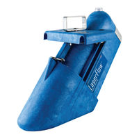
Teledyne TIENet 360 LaserFlow Ex Installation And Operation Manual (140 pages)
Velocity Sensor
Brand:
Teledyne
| Category:
Accessories
| Size: 7 MB
Table of Contents
Table of Contents
11
Section 1 Introduction
15
Description
15
Design
16
Measurement Technology
16
Cabling
16
Operation
16
Basic Laserflow System (Showing both AC and Battery-Powered Options)
16
Optional Submerged Functionality
17
Technical Specifications
18
Accessories
20
Ordering Information
20
Unpacking Instructions
22
Protective Window Cap
22
Remove Protective Window Cap before Installation
22
Section 2 Preparation and Installation
23
Safety
23
Site Conditions
23
Sensor Installation Considerations
24
Ultrasonic Beam Angle
24
High Water Levels
24
Submersion and Fouling
24
Humidity
24
Ultrasonic Level Sensor Beam Angle
24
Surface
25
Temperature
25
Waves
25
Wind
25
Installation Checklist
25
Connecting the Cable
25
Cable Connection: Signature Flow Meter
25
Tienet Device Terminal Strips
26
Installing Cable with a Cord-Grip Fitting
26
Tienet Device Terminal Connections
27
Attach Wired Terminal Strip to Case Board Socket
28
Insert the Cable Reference Tubing into the Case Board Reference Port
28
Position and Secure the Cable
29
Remote Ultrasonic Cable Connection
30
Ultrasonic Sensor
30
Preparing the Laserflow Connector Receptacle
30
Secure Caps and Connect 310 Ultrasonic Plug to Laserflow
30
Cable Connection: 2160 Laserflow Module
31
Preparing the 2160 Connector Receptacle
31
Secure Caps and Connect Laserflow to 2160
31
Sensor Installation Tools and Requirements
32
Tools Required
32
Sensor and Mounting Equipment Dimensions
32
Overall Dimensions Including Wall Mounting Hardware (Part 1)
33
Overall Dimensions Including Wall Mounting Hardware (Part 2)
34
Overall Dimensions Including Temporary Mounting Hardware (Part 1)
35
Overall Dimensions Including Temporary Mounting Hardware (Part 2)
36
Sensor Positioning and Requirements
37
Sensor Installation Constants
37
Typical Manhole Installation
38
Wall Mounting Kit
39
Wall Mount Installation
40
Wall Mount: Vertical Clamp and Vertical Clamp with Tube Coupler Inserted
40
Wall Mount: Sensor Carrier Installed on Tube Coupler
41
Wall Mount: Place the Sensor on the Carrier
42
Turn the Locking Handle Clockwise until Sensor Is Locked into Place (Shown with Op- Tional Sensor Retrieval Arm, Described in Section 2.8)
43
Turn the Locking Handle Clockwise until Sensor Is Locked into Place
43
Optional Sensor Retrieval Arm, Described in Section 2.8)
43
Temporary Mounting Kit
44
Temporary Mounting Installation
45
Temporary Mount: Remove Stationary Foot
45
Temporary Mount: Install Coupler, Replace Stationary Foot
45
Temp Mount: Securing the Coupler
46
Temporary Mount: Install Sensor Carrier/Knuckle Onto 24" Pipe
46
Installing the Sensor Carrier
47
Temporary Mount: Place the Sensor on the Carrier
48
Offset Carrier from Cargo Bar
49
Temporary Mount: Optional Elbow Pipe for Offset
49
Optional Sensor Retrieval Arm
50
Suggested Placement of Laserflow Sensor When Using Temporary Mounting Hard
50
Optional Sunshade
52
Remote Tienet™ Model 310 Ultrasonic Level Sensor
53
Section 3 Setup with Signature® Flow Meter
55
Configuring the System
55
Updating the Device List
55
Measurement Setup
58
Level
59
Velocity
59
Adjust 350 Level (Optional)
63
Velocity (Optional)
64
Advanced Settings (Optional)
65
Velocity Grid
67
Sensor Positioning and Adjustment
68
Centering the Laserflow Sensor
68
Laser Velocity Measurement Point Selection
68
Ultrasonic Level Adjustment
69
Contact Teledyne Isco
70
Section 4 Setup with 2160 Laserflow Module
71
Activating Connected Sensors
71
Measurement Display and Settings
73
Level
75
Velocity
77
Advanced Settings
78
Level (Optional)
85
Velocity (Optional)
87
Sensor Positioning and Adjustment
88
Centering the Laserflow Sensor
88
Section 5 Maintenance and Optional Kits
91
Maintenance
91
Firmware Updates
92
With Signature Flow Meter
92
With 2160 Laserflow Module
92
Cleaning the Sensor Housing
92
Accessing the Laserflow's Nose Piece
92
Removing the Nose Piece
93
Velocity Readings and the Laser Window
95
Cleaning the Laser Window
95
Installing the Optional Submerged Measurement Kit
97
Installation Procedure
97
Appendix A Replacement Parts
101
Replacement Parts Diagrams and Listings
101
Laserflow Sensor
102
Wall Mounting Hardware
108
Temporary Mounting Hardware
110
Replacement Sensors
112
Sensor Accessories
112
Appendix B Installation Checklist
113
Introduction
113
Equipment and Recommended Toolslaptop Computer
114
Site Information
114
Recommended Essential Parameters
117
Site Conditions
117
Sensor Positioning
120
Appendix C Velocity Error Codes
123
Introduction
123
Importing Data Dump (.Ddp) Files (Signature Only
123
Viewing Velocity Error Codes in Flowlink
125
Appendix D Material Safety Data Sheets
127
Advertisement
Teledyne TIENet 360 LaserFlow Ex Installation And Operation Manual (112 pages)
Velocity Sensor
Brand:
Teledyne
| Category:
Measuring Instruments
| Size: 15 MB
Table of Contents
Table of Contents
9
Section 1 Introduction
13
Laserflow Ex
13
Design of Laserflow Ex
14
Measurement Technology
14
Cabling
14
Operation
14
Technical Specifications
15
Accessories
17
Ordering Information
17
Unpacking Instructions
18
Protective Window Cap
18
Section 2 Preparation and Installation
19
Safety
19
Site Conditions
19
Installation in Hazardous Locations
20
Importantinformation Regarding "X" Marking
20
Electrical Requirements
21
Ambient Environment
21
Wiring Diagram
21
Laserflow Ex Control Drawing
22
Laserflow Ex Control Drawing
23
Sensor Installation Considerations
24
Ultrasonic Beam Angle
24
High Water Levels
24
Submersion and Fouling
24
Ultrasonic Level Sensor Beam Angle
24
Humidity
25
Surface
25
Temperature
25
Waves
25
Wind
25
Installation Checklist
25
Connecting the Cable
25
Cable Connection: Tienet Barrier
25
Cable Connection: Signature Flowmeter
26
Tienet Device Terminal Strips
27
Tienet Device Terminal Connections
28
Attach Wired Terminal Strip to Case Board Socket
29
Position and Secure the Cable
30
Remote Ultrasonic Cable Connection
31
Ultrasonic Sensor
31
Sensor Installation Tools and Requirements
32
Tools Required
32
Sensor and Mounting Equipment Dimensions
32
Overall Dimensions Including Wall Mounting Hardware (Part 1)
32
Overall Dimensions Including Wall Mounting Hardware (Part 2)
33
Sensor Positioning and Requirements
34
Typical Manhole Installation
35
Wall Mounting Kit
36
Wall Mount Installation
37
Wall Mount: Sensor Carrier Installed on Tube Coupler
38
Wall Mount: Place the Sensor on the Carrier
39
Optional Sunshade
41
Remote Tienet™ Model 310 Ultrasonic Level Sensor
42
Section 3 Setup with Signature® Flowmeter
43
Configuring the System
43
Updating the Device List
43
Measurement Setup
46
Measurement Setup: Sensor Input Settings
46
Level
47
Velocity
47
Laserflow Ex Velocity Advanced Settings
47
Blanking Distance for Laserflow Ex with Built-In Sensor or with Remote Ultrasonic
47
Measurement Setup: Advanced Settings for Laserflow Ex Sensor
50
Velocity Grid
51
Sensor Positioning and Adjustment
52
Centering the Laserflow Ex Sensor
52
Laser Velocity Measurement Point Selection
52
Ultrasonic Level Adjustment
53
Selection of Velocity Measurement Points
53
Contact Teledyne ISCO
54
Ultrasonic Level Adjustment
54
Section 4 Setup with 2160 Laserflow Module
55
Activating Connected Sensors
55
Activating Connected Sensors in Flowlink
56
Measurement Display and Settings
57
Measurements Tab: Displays Real-Time Measurements
57
Drop down List of Measurements for 2160 Module
58
Level
59
Level Measurement Tab in Flowlink
59
Blanking Distance for Laserflow Ex with Built-In Sensor or 310 Remote Ultrasonic
60
Velocity
61
Velocity Measurement Tab in Flowlink
61
Advanced Settings
62
Remote Distance Measurement with the 310 Remote Ultrasonic Sensor
64
Tal Sensor Mount Bracket
65
Laserflow Ex Placement Using Parallel to Channel Slope Option
66
Laserflow Ex Placement Using Slope Percentage Option
67
Sensor Positioning and Adjustment
68
Centering the Laserflow Ex Sensor
68
Laser Velocity Measurement Point Selection
69
Section 5 Maintenance and Optional Kits
71
Maintenance
71
Firmware Updates
72
With Signature Flowmeter
72
With 2160 Laserflow Module
72
Cleaning the Sensor Housing
72
Accessing the Laserflow Ex's Nose Piece
72
Removing the Nose Piece
73
Replacing the Nose Piece
74
Velocity Readings and the Laser Window
75
Cleaning the Laser Window
75
Installing the Remote Tienet™ 310 Ultrasonic Level Sensor
76
Appendix A Replacement Parts
77
Replacement Parts Diagrams and Listings
77
Laserflow Ex Sensor
78
Wall Mounting Hardware
80
Replacement Sensors
82
Sensor Accessories
82
Appendix B Installation Checklist
85
Introduction
85
Equipment and Recommended Tools
86
Site Information
86
Recommended Essential Parameters
89
Site Conditions
89
And Horizontal Mount Bracket
90
B-4 Placement of Laserflow Ex with Remote Ultrasonic Sensor
91
Sensor Positioning
92
Appendix C Velocity Error Codes
95
Introduction
95
Importing Data Dump (.Ddp) Files (Signature Only
95
C-1 Signature Flow Data: Selecting the .Ddp File(S)
96
Viewing Velocity Error Codes in Flowlink
97
Appendix D Material Safety Data Sheets
99
Character Grid
105
Sensor
106
Advertisement
Related Products
Teledyne 300M
Teledyne 3350
Teledyne 3300TB
Teledyne TIENet 301
Teledyne 300E
Teledyne 300
Teledyne 322
Teledyne 3700
Teledyne TIENet 306
Teledyne LeCroy WaveStation 3162
Teledyne Categories
Measuring Instruments
Analytical Instruments
Test Equipment
Digital Camera
Laboratory Equipment
More Teledyne Manuals
Login
Sign In
OR
Sign in with Facebook
Sign in with Google
Upload manual
Upload from disk
Upload from URL