Sign In
Upload
Manuals
Brands
Teledyne Manuals
Laboratory Equipment
3700
Teledyne 3700 Manuals
Manuals and User Guides for Teledyne 3700. We have
1
Teledyne 3700 manual available for free PDF download: Installation And Operation Manual
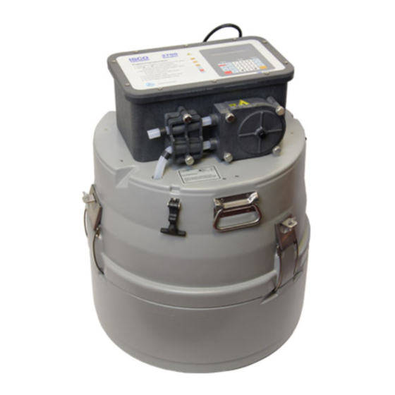
Teledyne 3700 Installation And Operation Manual (242 pages)
Portable Samplers
Brand:
Teledyne
| Category:
Laboratory Equipment
| Size: 8 MB
Table of Contents
Table of Contents
7
Section 1 Introduction
13
Introduction
13
3700 Standard Description
13
3700 Compact Description
14
Programmable Features
14
Flexible Sampling Intervals
15
Multiplexing
15
STORM Sampling
16
Master/Slave Sampling
17
Accurate Sample Volumes
17
Flexible Start Times
17
Foreign Languages and Metric Units of Measure
18
Delivery System
18
Liquid Detector
18
Pump Tubing and Suction Lines
18
Strainers
19
Bottle Configurations
19
Compatible Equipment
20
Isco Flow Meters
20
Non-Isco Flow Meters
21
Samplink for Sampling Data Retrieval
21
Liquid Level Actuator
22
Master/Slave Cables
22
Power Options
20
Technical Specifications
22
Technical Specifications for the 3700 Portable Samplers
22
Section 2 Setup Procedures
25
Assembly and Disassembly of the Case
25
Preparing the Base Section
25
Standard Base Section
25
Compact Base Section
25
Bottles
26
Cooling the Samples
26
Suction Line
26
Attaching Vinyl Suction Line
27
Attaching PTFE Suction Line
28
Routing of the Suction Line
28
Strainers
28
Standard Weighted Polypropylene Strainer
28
Intake Placement
29
Connection to Power Source
29
Stainless Steel Strainer
29
Placement of the Sampler into Operation
30
Placement of the Sampler Adjacent to Manhole
30
Connection to a Flow Meter
31
Saving Program Settings
31
Recovering the Sampler
31
Exchanging Sampler Tubs
31
Restarting
31
Sampler Locking
31
Locking the Sampler
32
Locked Sampler
33
Section 3 Programming Guidelines
36
Description of Sampling Operation
36
Sample Events and the Sampling Cycle
36
Types of Samples
36
Types of Sample Pacing
37
Types of Sample Distribution
37
Sequential Sample Distribution
37
Samples-Per-Bottle Multiplexing
39
Bottles-Per-Sample Multiplexing
39
Types of Sampling Available in Extended Programming Mode
40
Nonuniform Time Intervals
40
Extended Multiplexing
40
Multiple-Bottle Compositing
41
Stops and Resumes
41
Stormwater Sampling
41
Storm-Event Sample Distribution Schemes
42
Programming Introduction
42
Operating States
42
Storm Distribution Scheme
42
Programming Modes
43
Interactive State Structure
44
Configure Option Functions
45
Configure Sequence
46
Programming Procedure
46
Following Display Cues
47
Keypad Description
47
Control Panel
48
Displays
50
Programming Examples
52
Basic Programming Mode: Program Sequence Structure
54
Basic Programming Procedure
55
Configure Sequence
72
Set Clock
72
Bottles and Sizes
72
Portable or Refrigerated Sampler
73
Suction Line
74
Bottle Volume Settings for Standard Bottle Configurations
74
Liquid Detector
75
Programming Mode
76
Load Stored Program
78
Save Current Program
79
Flow-Mode Sampling
80
Nonuniform Time
81
Calibrate Sampler
81
Sampling Stop/Resume
81
Start Time Delay
81
Enable Pin
82
Event Mark
84
Event Mark and Bottle Number Signal Output
85
Purge Counts
86
Tubing Life
86
Program Lock
86
Sampler ID
86
Run Diagnostics
86
Exit Configuration
87
Save Current Program
88
Factory Configure Option Settings
88
Factory Program Settings
89
Extended Programming Mode
90
Extended Mode Sample Pacing
91
Extended Mode Sample Distribution
91
Time-Paced Multiplexed (Samples-Per-Bottle) Sampling
91
Extended Mode Sample Volumes
92
Extended Mode Key Times
92
Programming Mode: Sample Pacing and Distribution
93
Extended Programming Mode: Sample Volume and Key Times
94
Extended Programming Mode: STORM Programming
95
Sampling Stop/Resume
96
Start Times
96
Events Preceding Sampling Routine
96
Simplified Start Time Diagram
97
Nonuniform Times and Disable Signals
98
Manual Sample Key and Programmed Start Times
98
Start Time Displays
98
Start Time Diagram
99
Start Time Diagram for Nonuniform Time Routines
100
Stormwater Sampling
101
Storm Sampling Checklist
101
Recommended Configurations for Storm Sampling
103
Programming the Sampler for a Storm Routine
105
First Section: First Bottle Group Settings
105
Storm Sampling: Flow Pacing for the Second Bottle Group
106
Storm Sampling: Time Pacing for the Second Bottle Group
107
Second Section: Second Bottle Group
108
Flow-Paced Multiplexed (Bottles-Per-Sample) Sampling
108
Foreign Languages and Metric Units of Measure
113
Start Time Diagram for STORM Routines
113
Extended Programming Examples
114
Storm Sampling
129
Standby State
131
Operable Keys in Standby State
131
Program Started Later than Programmed Start Time
133
Displayed Selections and Messages
134
Additional Displays
135
Display Status
135
Reviewing or Printing Program Information
136
Reviewing the Sampling Results
137
Source of Sample Event
138
Error Messages and Missed Samples
139
Run State
140
Run State Displays: Time-Paced Sampling
141
Run State Displays: Flow-Paced Sampling
142
Run State Displays: Composite Sampling
143
Section 4 Options and Interfacing Equipment
145
Introduction
145
Composite Sampling
145
Conversion Procedure
145
Standard Sample Bottle Tub
146
Optional Composite Tub
146
Composite Sampling: Float and Float Cage Installed on Center Section
146
Programming and Configuring for Composite Sampling
147
Connections to External Devices
147
Isco Flow Meters and Flow Loggers
147
Non-Isco Flow Meters
148
Flow Meter Connector Wiring
148
Printer Connector Wiring
148
Ma Flow Signals
149
1640 Liquid Level Actuator
149
Ma Sampler Input Interface
149
Master/Slave Connections
150
Section 5 Routine Maintenance
153
Cleaning the Sampler
153
Cleaning Protocols for Priority Pollutants
153
Pump Tubing
155
Inspection of Pump Tubing
155
Removing the Pump Tubing
156
Interior of 3700 Standard Center Section: View of the Pump Tube
157
Liquid Detector and Pump Housing
158
Installing a New Pump Tube
159
Suction Line
160
Vinyl Suction Line
160
PTFE Suction Line
160
Internal Desiccant
161
Location of 10 Screws on Control Box Lid
162
Internal Desiccant (Controller Lid Removed)
163
Section 6 Servicing
165
Controller
165
If Serious Problems Occur
165
Processor Servicing
165
Removal of the Control Box
166
Access to Electronic Components
167
Underside of the Control Box Cover
168
Removal of the Distributor Gear Case Assembly
169
Main Circuit Board
169
Removal of the Pump Gear Case Assembly
170
Precautions for Servicing CMOS Circuitry
171
Preliminary Electronics Troubleshooting
172
Circuit Boards
173
Main Board
173
Main Circuit Board Component Layout
175
Pump Control Board
176
Sample Event Cycle and Delivery of Sample Volumes
177
Volumetric Determination
177
Sample Delivery
177
Sample Volume Variation
178
Appendix A Replacement Parts Lists
179
Appendix B Accessories
197
General Accessories
197
Bottles, Caps, and Retaining Rings
197
Suction Lines and Strainers
198
Power Sources
199
Interfacing Equipment
199
Appendix C General Safety Procedures
201
Practical Safety Precautions
201
Lethal Atmospheres in Sewers
204
Hazardous Gases
206
Time Line
211
Display Index
211
Appendix D Display Index
212
Load Stored Program
218
Appendix E Calculating Flow Increment between Samples
221
Appendix F Glossary
225
Appendix G Material Safety Data Sheets
227
Advertisement
Advertisement
Related Products
Teledyne Everywhereyoulook IsoPlane 320A
Teledyne 3700R
Teledyne 3700FR
Teledyne 300P
Teledyne 311-D
Teledyne 310
Teledyne 326
Teledyne 3060E
Teledyne 3350
Teledyne 307WA
Teledyne Categories
Measuring Instruments
Analytical Instruments
Test Equipment
Digital Camera
Laboratory Equipment
More Teledyne Manuals
Login
Sign In
OR
Sign in with Facebook
Sign in with Google
Upload manual
Upload from disk
Upload from URL