Sign In
Upload
Manuals
Brands
Powerware Manuals
UPS
9315s
Powerware 9315s Manuals
Manuals and User Guides for Powerware 9315s. We have
1
Powerware 9315s manual available for free PDF download: Installation & Operation Manual
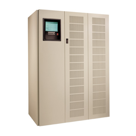
Powerware 9315s Installation & Operation Manual (205 pages)
Parallel Capacity/Redundant UPS with PowerHandler Plus Switchboard System Bypass Module (SSBM)
Brand:
Powerware
| Category:
UPS
| Size: 7 MB
Table of Contents
Instructions Importantes Concernant la Sécurité
2
Save These Instructions
2
Important Safety Instructions
2
Table of Contents
3
List of Tables
11
Introduction
13
Figure 1. Typical Parallel Capacity/Redundant System with Ssbm
14
Basic System Configurations
15
Getting Started 1
16
Using this Manual
16
Conventions Used in this Manual
17
Safety Considerations
18
For more Information
19
Getting Help
20
Installation
21
Section I
21
1 Getting Started
23
Installing the UPS
23
Creating an Installation Plan
23
Preparing Your Site
24
Environment Considerations
24
Preparing for Wiring the Parallel Capacity/Redundant System
24
Inspecting and Unpacking each Cabinet
26
Figure 1---1. Cabinets as Shipped, with Outer Packaging and Pallet
26
2 Installing the Parallel Capacity/Redundant System
29
Preliminary Installation Information
29
Installing the Switchboard System Bypass Module
30
Installing Optional System Maintenance Bypass (SMB)
31
Installing the Powerware Static Switch
32
Installing a Fully Rated Static Switch (4000A)
32
Installing SSBM or SMB Circuit Breakers
32
Installing an SSBM or SMB Circuit Breaker
32
Setting the Power+ Trip Unit
33
Installing UPM Cabinets
33
Installing SSBM Wiring
33
Installing Optional SMB Wiring
34
Preparing for Installing Optional Accessories
34
2.10 Initial Startup
34
2.11 Completing the Installation Checklist
34
2.12 Installation Checklist
35
Figure 3---1. Remote Epo Control
37
3 Installing a Remote EPO Control
37
Installing a Remote Monitor Panel
39
Installation Procedures
39
Figure 4---1. Remote Monitor Panel (Rmp)
40
Figure 4---2. Terminal Block Bracket
41
Figure 5---2. Terminal Block Bracket
44
To Install a RIM
44
Installing a Supervisory Contact Module
47
Rev. a
47
Figure 6---2. Terminal Block Bracket
48
To Install a Supervisory Contact Module
48
Operation
51
To Install an RMP
41
Installing a Relay Interface Module
43
7 Understanding Parallel Capacity/Redundant System Operation
53
Looking Inside the Parallel Capacity/Redundant System
53
Battery Mode 7
55
Normal Mode 7
55
Bypass Mode 7
55
Normal Mode
56
Bypass Mode
57
Battery Mode
58
Figure 7---3. Path of Current through the Parallel Capacity/Redundant
58
Load Bank Mode
59
Maintenance Bypass Mode (Optional) 7
62
Redundant CBP Mode (Optional) 7
62
Optional Modes of Parallel Operation
62
Maintenance Bypass and Redundant CBP
62
Maintenance Bypass Mode (Optional)
63
Redundant CBP Mode (Optional)
64
8 Operational Controls Andfeatures
67
Operational Controls and Features
67
General
67
SSBM Standard Features
67
Control Panel
67
SSBM Circuit Breakers
67
Figure 8---1. Typical Ssbm Control Section (Sheet 1 Of)
68
Figure 8---1. Typical Ssbm Control Section (Sheet 2 Of)
69
Figure 8---1. Typical Ssbm Control Section (Sheet 3 Of)
70
Figure 8---1. Typical Ssbm Control Section (Sheet 4 Of)
71
SMB Circuit Breakers
72
Fully Rated Static Switch
72
Emergency Upm off
72
Customer Interface Panel
72
Customer Convenience Outlet
72
Installation Features
72
Options and Accessories
73
Remote Monitor Panel
73
Relay Interface Module
73
Modem
73
Safety Considerations
74
Symbols, Controls, and Indicators
75
Using the Control Panel 9
77
Description 9
77
Figure 9---1. Parallel/Capacity Control Panel
77
Using the LCD Screen 9
78
Figure 9---2. Parts of the Lcd Screen
78
Figure 9---3. System Meters Screen
81
Load Amp Meters Screen 9
82
Software Versions Screen 9
83
Adjusting the Contrast 9
79
Using the Pushbuttons 9
79
Reading the Status Indicators 9
80
System Meters Screen 9
81
Using the Menu Options 9
81
Figure 9---5. Versions Screen
83
System History Screen 9
84
Figure 9---6. Event History Log Screen
84
Active System Events Screen 9
85
Figure 9---7. Active System Events Screen
85
Unit Statistics Screen 9
86
Figure 9
86
MIMIC Screen 9
87
Time Setup Screen 9
88
Figure 9---10. Time Setup Screen
88
Port Setup Screen 9
89
Figure 9---11. Port Setup Screen
89
Initial Setup 10
91
Manual Start 10
92
Auto Start
93
SSBM Shutdown to Bypass 10
94
Single UPM Shutdown
94
Restarting a Single UPM 10
95
Using the UPM LOAD off Pushbutton
95
Resetting the UPM after LOAD off
96
To Use the SSBM EMERGENCY UPM off Pushbutton 10
97
Initial Setup 10
98
Manual Start 10
99
Single Upm Shutdown
100
SSBM Shutdown to Bypass 10
101
Restarting a Single UPM 10
101
Rev. a
101
To Use the UPM EMERGENCY UPM off Pushbutton 10
102
Resetting the Upm after an Emergency Upm Shutdown
102
Using the Upm Emergency Upm off Pushbutton
102
To Use the SSBM EMERGENCY UPM off Pushbutton 10
103
Operation with Electrical Controls
105
General Purpose Relay Contacts
109
11 Using Features and Options
109
Building Alarm Monitoring
109
Remote Monitor Panel
110
Figure 11
110
Relay Interface Module
112
Figure 11
112
Supervisory Contact Module
113
Figure 11
113
External Battery Disconnect for Common Battery Racks
114
Common Battery Racks
114
12 Responding to System Events
115
System Event Lights
115
System Event Horns
115
System Event Messages
116
Connecting Equipment to a Serial Port
123
Locating the Communications Panel
123
13 Serial Communications
123
Figure 13
124
Figure 13
125
Configuring the Serial Ports
126
Figure 13
126
Figure 13---3. Setup Serial Port 1 Screen
126
Default Settings
128
Printing Selected Information
129
Terminal Mode
129
Entire Log (Ctrl + P)
130
Figure 13
131
Figure 13---5. System Meters Screen
131
Meters Printout (Ctrl + M)
131
System Information Printout (Ctrl + A)
131
Program Building Alarms 13
132
System Configuration
132
System Configuration Mode Main Menu
132
Enable/Disable Default Functions 13
133
Customize Alarm Messages
134
Change Password
135
Program Unit Name
135
Battery Test Setup 13
136
Rev. a
136
Calibration Mode
137
Computer Mode
137
Modify Low Battery Time
137
Remote Monitor Mode
137
14 Remote Notification
139
Remote Notification Features
140
Description of Operation
140
Call Answer
140
Call out
141
Hardware Requirements
142
Basic Modem Configuration
143
Configuring the Modem
143
Configuring the Modem to Call a Remote Computer
144
Configuring the Modem to Call a Numeric Pager
145
Final Modem Configuration
146
Ssbm Setup Configuration
147
User Selected Events
148
Maintaining the Parallel Capacity/Redundant System
151
Performing Preventive Maintenance
153
Maintenance Training
154
Circuit Breakers
154
Short Circuits
154
16 Product Specifications
155
Model Numbers
155
Ssbm Input
155
Environmental Specifications
156
Ssbm Output
156
Rev. a
157
Appendix A
157
Advertisement
Advertisement
Related Products
Powerware 9170+
Powerware 9355
Powerware 9335
Powerware 9330
Powerware 9390
Powerware 9320
Powerware 9305
Powerware 9125 PowerPass
Powerware 9305 HS Series
Powerware 9350
Powerware Categories
UPS
Power Supply
Surge Protector
Control Unit
Power distribution unit
More Powerware Manuals
Login
Sign In
OR
Sign in with Facebook
Sign in with Google
Upload manual
Upload from disk
Upload from URL