Sign In
Upload
Manuals
Brands
Nortel Manuals
Software
Passport 8000 Series
Nortel Passport 8000 Series Manuals
Manuals and User Guides for Nortel Passport 8000 Series. We have
3
Nortel Passport 8000 Series manuals available for free PDF download: Configuring, Installing And Maintaining
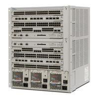
Nortel Passport 8000 Series Configuring (226 pages)
Nortel Passport 8600: User Guide
Brand:
Nortel
| Category:
Software
| Size: 1.67 MB
Table of Contents
Restricted Rights Legend
2
Statement of Conditions
2
Table of Contents
5
Revision History
15
Before You Begin
17
Preface
17
Text Conventions
18
Acronyms
19
Hard-Copy Technical Manuals
19
How to Get Help
19
Chapter 1 Managing the Switch
22
Switch Management Tools
22
Command Line Interface (CLI)
23
Device Manager
23
Web Management Interface
23
Dynamic Network Applications
24
Snmp
24
SNMP Communities
25
Rmon
26
Chapter 2 Configuring RMON
28
Configuring RMON Using Device Manager
29
Layer 2 / Layer 3 Redundancy Clarification
29
L3 Redundancy Limitations and Considerations
29
Enabling RMON Globally
30
Using Ethernet Statistics
31
Enabling RMON Statistics (Default)
31
Figure 1 Enabling RMON Statistics on a Port
32
Verifying RMON Statistics
33
Table 1 Port Shortcut Menu Fields
33
Enabling RMON Statistics (Nondefault)
34
Table 2 Rmoncontrol Ethernet Statistics Tab Fields
34
Figure 2 Rmoncontrol Dialog Box-Ethernet Statistics
34
Table 3 Rmoncontrol, Insert Ethernet Statistics Tab Fields
35
Figure 3 Rmoncontrol and Insert Ethernet Statistics Dialog Boxes
35
Disabling RMON Statistics
36
Viewing Statistics
36
Understanding RMON History
37
Enabling RMON History (Default)
37
Figure 4 Graphport Dialog Box-Interface Tab
37
Enabling RMON History (Nondefault)
38
Table 4 Rmoncontrol Dialog Box Fields
39
Figure 5 Rmoncontrol and Rmoncontrol, Insert History Dialog Boxes
39
Disabling RMON History
41
Viewing History
41
Configuring RMON Alarms
42
Figure 6 Graphport Dialog Box-RMON History Tab
42
Figure 7 How Alarms Fire
43
Creating Alarms
44
Figure 8 Alarm Example-Threshold Less than 260
44
Figure 9 Alarm Manager Dialog Box
46
Creating a Port History Alarm
47
Figure 10 Enabling RMON Statistics and History
48
Figure 11 Chassis Dialog Box-Trap Receivers Tab
49
Figure 12 Chassis, Insert Trap Receivers Dialog Box
49
Viewing RMON Statistics
49
Deleting Alarms
50
Figure 13 Rmonalarms Dialog Box-Events Tab
50
Viewing Log Files
50
Understanding RMON Events
51
Figure 14 Deleting an Alarm
51
Creating Events (Default)
52
Creating Events (Nondefault)
52
Figure 15 Rmonalarms, Insert Events Dialog Box
53
Figure 16 Rmonalarms Dialog Box-Events Tab
53
Viewing Events
53
Deleting Events
54
Table 6 Rmonalarms Dialog Box-Events Tab Fields
54
HP Openview
55
Understanding the "Log Only" Event Bug
56
Working Around the Private Management Trap Bug
57
Configuring RMON Using the CLI
58
Configuration Example
60
Viewing RMON Settings
61
Chapter 3 Configuring the Web Management Interface
66
Monitoring the Switch Using Web Management
66
Requirements
67
Installing Help Files
67
Installing Help Files in a Windows Environment
68
Installing Help Files in a UNIX Environment
68
Specifying the Help File Location
68
Enabling the Web Server Using Device Manager
69
Figure 17 Chassis Dialog Box-System Tab
70
Figure 18 Security Dialog Box-Web Tab
71
Enabling the Web Server Using the CLI
72
Table 7 Web Tab Fields
72
Showing Web-Server Status
74
66 Chapter 66 66 Chapter 3 Configuring the Web Management Interface
75
Accessing the Web Interface
75
Figure 19 Web Logon Page
75
Troubleshooting Web Interface Access to a Switch
76
78 Chapter 78 78 Chapter 4 Configuring and Graphing Ports
78
Configuring a Port
78
Editing Ports
80
Setting a Basic Configuration
80
Table 8 Interface Tab Fields
82
Opening a Dual Tab
84
Table 9 Dual Tab Fields
85
Figure 21 Port Dialog Box-Dual Tab
85
Configuring Routing Operations
86
Assigning an IP Address on a Brouter Port
86
Figure 24 Port, Insert IP Address Dialog Box
88
Table 10 Port, Insert IP Address Dialog Box Fields
89
Configuring Vlans
90
Table 11 VLAN Tab Fields
91
Detecting VLAN Loops
92
Table 12 Loopdetect Dialog Box Fields
92
Figure 26 Loop Detected Dialog Box
92
Configuring Spanning Tree Groups (STG)
94
Table 13 STG Tab Fields
94
Configuring MAC Learning Parameters
95
Table 14 MAC Learning Tab Fields
96
Setting Rate Limits
98
Table 15 Rate Limiting Tab Fields
98
Testing Ports
100
Figure 30 Port Dialog Box-Test Tab
100
Table 16 Test Tab Fields
101
Performing an External Loopback Test
102
Performing an Internal Loopback Test
102
Configuring Address Resolution Protocols (ARP)
103
Table 17 ARP Tab Fields
104
Configuring Dynamic Host Configuration Protocol (DHCP)
105
Table 18 DHCP Tab Fields
106
Configuring Distance Vector Multicast Routing Protocol (DVMRP)
107
Table 19 DVMRP Tab Fields
108
Configuring Internet Group Management Protocol (IGMP)
109
Table 20 IGMP Tab Fields
110
Configuring Open Shortest Path First (OSPF)
111
Table 21 OSPF Tab Fields
112
Configuring Routing Information Protocol (RIP)
113
Table 22 RIP Tab Fields
114
Configuring Protocol Independent Multicast (PIM)
116
Configuring Pragmatic General Multicast
117
Table 23 PIM Tab Fields
117
Table 24 PGM Tab Fields
118
Configuring Virtual Router Redundancy Protocol (VRRP)
119
Figure 40 Port, Insert VRRP Dialog Box
120
Table 25 VRRP Tab Fields
121
Discovering Routers
123
Inserting an IPX Brouter
124
Table 26 Router Discovery Tab Fields
124
Figure 43 Port, Insert IPX Brouter Dialog Box
125
Table 27 Insert IPX Brouter Dialog Box Fields
126
Graphing Port Statistics
127
Graphing Interface Statistics
127
Table 28 Graph Interface Tab Fields
128
Graphing Ethernet Error Statistics
130
Table 29 Ethernet Errors Tab Fields
131
Graphing Bridging Statistics
134
Table 30 Bridging Tab Fields
134
Graphing Spanning Tree Statistics
135
Graphing Unicast and Multicast Traffic Statistics
136
Table 31 Spanning Tree Tab Fields
136
Graphing RMON Statistics
138
Table 32 Routing Tab Fields
138
Figure 49 Graphport Dialog Box-RMON Tab
139
Graphing RMON History Statistics
140
Figure 50 Graphport Dialog Box-RMON History Tab
141
Graphing DCHP Statistics
143
Figure 51 Port Dialog Box-DHCP Tab
143
Table 35 DHCP Tab Fields
144
Figure 52 Graphport Dialog Box-DHCP Tab
144
Graphing OSPF Statistics
145
Figure 53 Graphport Dialog Box-OSPF Tab
145
Table 36 OSPF Tab Fields
146
Graphing VRRP Statistics
147
Figure 54 VRRP Dialog Box-VRRP Stats Tab
147
Table 37 VRRP Tab Fields
148
Chapter 4 Configuring and Graphing Ports
78
Chapter 5 Configuring and Graphing Chassis Information
150
Editing the Chassis
150
Editing System Information
151
Figure 55 Chassis Dialog Box-System Tab
152
Table 38 System Tab Fields
153
Editing Chassis Information
154
Table 39 Chassis Tab Fields
155
Figure 56 Chassis Dialog Box-Chassis Tab
155
Enabling L2/L3Static Routes
157
Figure 57 Chassis Dialog Box-L2/L3 Redundancy Tab
157
Disabling L2/L3Static Routes
158
Figure 58 Enable HA-CPU Message Box
158
Figure 59 Disable HA-CPU Message Box
158
Viewing L2/L3 Redundancy Status
159
Table 40 L2 Redundancy Tab Fields
160
Reserving Records
161
Figure 60 Chassis Dialog Box-Record Reservation Tab
161
Viewing the Boot Configuration
162
Table 41 Boot Config Tab Fields
162
Figure 61 Chassis Dialog Box-Boot Config Tab
162
Editing Trap Receivers
163
Checking System Performance
164
Table 42 Trap Receivers Tab Fields
164
Setting the Time
165
Table 43 Performance Tab Fields
165
Figure 63 Chassis Dialog Box-Performance Tab
165
Table 44 User Set Time Tab Fields
166
Figure 64 Chassis Dialog Box-User Set Time Tab
166
Editing Cards
167
Editing Card Information
167
Table 45 Card Tab Fields
168
Figure 65 Card Dialog Box-Card Tab
168
Editing Boot File
169
Figure 66 Card Dialog Box-Boot Tab
170
Table 46 Boot Tab Fields
171
Displaying Flash and PCMCIA Statistics
172
Figure 67 Card Dialog Box-Device Tab
172
Displaying Flash File Information
173
Table 47 Device Tab Fields
173
Displaying PCMCIA File Information
174
Table 48 Flash Files Tab Fields
174
Figure 68 Card Dialog Box-Flash Files Tab
174
Table 49 PCMCIA Files Tab Fields
175
Figure 69 Card Dialog Box-PCMCIA Files Tab
175
Editing Objects
176
Editing Management Port
176
Table 50 Mgmt Port Dialog Box Fields
177
Figure 70 Mgmt Port Dialog Box
177
Editing Management Port Route Table
178
Table 51 Mgmt Port Route Table, Insert CPU Route Table Dialog Box Fields
179
Figure 71 Mgmt Port Route Table, Insert CPU Route Table Dialog Box
179
Editing Serial Ports
180
Table 52 Serial Port Dialog Box Fields
181
Figure 72 Serial Port Dialog Box
181
Editing Fans
182
Editing Mdas
183
Table 53 Fan Dialog Box Fields
183
Figure 73 Fan Dialog Box
183
Table 54 MDA Dialog Box Fields
184
Figure 74 MDA Dialog Box
184
Editing Power Supplies
185
Figure 75 Powersupply Dialog Box
185
Editing Filesystem
186
Copying a PCMCIA or Flash File
186
Table 55 Powersupply Detail Tab Fields
186
Table 56 Copy File Tab Fields
187
Figure 76 Filesystem Dialog Box-Copy File Tab
187
Displaying Flash and PCMCIA Statistics
188
Table 57 Device Info Tab Fields
188
Displaying Flash File Information
189
Table 58 Flash Files Tab Fields
189
Figure 78 Filesystem Dialog Box-Flash Files Tab
189
Displaying PCMCIA File Information
190
Table 59 PCMCIA Files Tab Fields
190
Figure 79 Filesystem Dialog Box-PCMCIA Files Tab
190
Editing ATM and POS
191
Graphing Chassis Statistics
192
Graphing SNMP Statistics
193
Table 60 SNMP Tab Fields
194
Graphing IP Statistics
195
Table 61 IP Tab Fields
196
Graphing ICMP in Statistics
198
Graphing ICMP out Statistics
200
Table 62 ICMP in Tab Fields
200
Table 63 ICMP out Tab Fields
201
Graphing OSPF Statistics
202
Table 64 OSPF Tab Fields
203
Appendix A
206
RMON Alarm Variables
206
Index
221
Advertisement
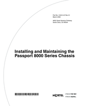
Nortel Passport 8000 Series Installing And Maintaining (120 pages)
Brand:
Nortel
| Category:
Chassis
| Size: 2.52 MB
Table of Contents
Table of Contents
11
Before You Begin
19
Preface
19
Hard-Copy Technical Manuals
20
Text Conventions
20
How to Get Help
21
Chapter 1 Passport 8000 Series Chassis Hardware Components
23
8010 Chassis
23
8010Co Chassis
24
Figure 1 8010Co Chassis and Components
25
8010 Chassis
26
8006 Chassis
28
Figure 2 8010 Chassis and Components
28
8003 Chassis
30
Figure 3 8006 Chassis and Components
30
Power Supplies
31
Figure 4 8003 Chassis and Components
31
Fan Trays
33
Table 1 Number of Fan Trays Installed each Chassis
33
Chapter 2 Installing the 8010, 8006, and 8003 Chassis
35
Preparing to Install the 8010, 8006, and 8003 Chassis
35
Shipment Contents
36
Table 2 Chassis Shipping Accessories: 8010, 8006, 8003
36
Figure 5 Items in the 8010 Chassis Shipping Container
37
Figure 6 Items in the 8006 Chassis Shipping Container
38
Supplying Equipment
39
Management Console
39
Figure 7 Items in the 8003 Chassis Shipping Container
39
Cables
40
Hardware for Mounting the 8010, 8006, 8003 Chassis in an Equipment Rack
40
Site Requirements
40
Space Requirements
40
AC Input Electrical Requirements (8010, 8006 and 8003 Chassis)
41
DC Input Electrical Requirements (8010 and 8006 Chassis)
41
Environmental Requirements
41
Installing the Chassis
41
Table 3 Electrical Requirements for the DC Models
41
Table 4 Environmental Requirements
41
Positioning the 8010, 8006, and 8003 Chassis on a Flat Surface
42
Table 5 Chassis Weight Including Components and Cables
42
Mounting the 8010, 8006, and 8003 Chassis in an Equipment Rack
43
Table 6 Maximum Number of Chassis in 7-Foot Rack
43
Figure 8 Positioning the Rack-Mounting Brackets: 8010 Chassis
44
Figure 9 Positioning the Rack-Mounting Brackets: 8006 Chassis
44
Figure 10 Positioning the Rack-Mounting Brackets: 8003 Chassis
45
Figure 11 Attaching the Rack-Mounting Brackets to the Chassis: 8010 Chassis
45
Figure 12 Attaching the Rack-Mounting Brackets to the Chassis: 8006 Chassis
45
Figure 13 Attaching the Rack-Mounting Brackets to the Chassis: 8003 Chassis
46
Table 7 Number of Rack Units to Allocate for Chassis
46
Figure 14 Aligning the Rack-Mounting Brackets with the Equipment Rack
47
Figure 17 Installing the 8010 Chassis in an Equipment Rack
48
Figure 18 Installing the 8006 Chassis in an Equipment Rack
48
Figure 19 Installing the 8003 Chassis in an Equipment Rack
49
Figure 20 Loosening the Rack-Mounting Screws: 8010 Chassis
49
Installing the Cable Guides
49
Figure 21 Loosening the Rack-Mounting Screws: 8006 Chassis
50
Figure 22 Loosening the Rack-Mounting Screws: 8003 Chassis
50
Figure 23 Sliding the Cable Guide Onto the Screws (8010 and 8006 Chassis)
50
Figure 24 Sliding the Cable Guide Onto the Screws: 8003 Chassis
51
Figure 25 Securing the Cable Guide to the Chassis: 8010 Chassis
51
Figure 26 Securing the Cable Guide to the Chassis: 8006 Chassis
51
Figure 27 Securing the Cable Guide to the Chassis: 8003 Chassis
52
Chapter 3 Installing the 8010Co Chassis
53
Preparing to Install the 8010Co Chassis
53
Shipment Contents
54
Table 8 8010Co Chassis Shipping Accessories
54
Figure 28 Accessories in the 8010Co Chassis Shipping Container
55
Supplying Equipment
56
Cables
56
Hardware for Mounting the Chassis in an Equipment Rack
56
Management Console
56
Site Requirements
57
Space Requirements
57
AC Input Electrical Requirements
57
DC Input Electrical Requirements
57
Table 9 DC Power Requirement for BIP
57
Environmental Requirements
58
Installing the Chassis
58
Table 10 Environmental Requirements
58
Mounting the 8010Co Chassis in a Two-Post Rack
59
Figure 29 Two 8010Co Chassis with BIP in a Two-Post Rack
60
Mounting the 8010Co Chassis in a 19-Inch Rack
61
Figure 30 Installing the Installation Shelf in a 19-Inch Equipment Rack
62
Figure 31 Installing the 8010Co Chassis in a 19-Inch Two-Post Rack
63
Figure 32 Installing the Installation Shelf in a Hendry Rack
64
Mounting the 8010Co Chassis in a Hendry Rack
64
Figure 33 Removing the Mounting Rails from the 8010Co Chassis
65
Figure 34 Installing the Mounting Rails for a Hendry Rack
66
Installing the Cable Management Brackets
67
Figure 35 Installing Cable Management Brackets
68
Grounding the 8010Co Chassis
69
Figure 36 Location of 8010Co Chassis Ground Studs
69
Figure 37 Chassis and 8004DC Power Supply Grounding Example
71
Table 11 Item Description for Chassis and 8004DC Power Supply Grounding
72
Figure 38 Chassis and AC Power Supply Grounding Example
73
Table 12 Item Description for Chassis and AC Power Supply Grounding
74
Connecting the Ground Cables to the Rack Grounding Strip
75
Figure 39 Rack Grounding Strip Example
75
Chapter 4 Operating the Passport 8000 Series Switch
77
Turning the Passport 8000 Series Switch on and off
78
Turning DC Power Supplies on and off
78
Figure 40 DC Power Supply Power Switch
79
Turning AC Power Supplies on and off
80
Verifying a Successful Installation
81
Configuring the Chassis to Operate in Default, M, or R Mode
82
Resetting the Passport 8000 Series Switch
82
Installing Removable Flash Memory Cards
83
Figure 41 Reset Button
83
Figure 42 Inserting a Removable Flash Memory Card: 8010Co Chassis
84
Figure 43 Inserting a Removable Flash Memory Card: 8010, 8006, and 8003 Chassis
84
Removing Removable Flash Memory Cards
85
Figure 44 Removing a Removable Flash Memory Card: 8010Co Chassis
85
Protecting Memory Card Files
86
Figure 45 Removing a Removable Flash Memory Card: 8010, 8006, 8003 Chassis
86
Replacing an Air Filter (8010Co Chassis Only)
87
Figure 46 Memory Card Read-Write Protect Switch
87
Removing and Inserting an Air Filter (8010Co Chassis Only)
88
Table 13 8010Co Air Filter Physical Specifications
88
Figure 47 Inserting an Air Filter into the 8010Co Chassis
89
Troubleshooting
90
LED Indications of Problems
90
Table 14 LED Problem Indicators
90
Apparent Module Failure
91
Module Failure Work Around 1
91
Module Failure Work Around 2
92
Failure to Get a Login Prompt from the Console Port
92
Figure 48 DCE/DTE Switch
92
Cable Connection Problems
93
10BASE-T Cables
93
100BASE-T and 1000BASE-T Cables
93
GBIC Cables
94
Appendix A Technical Specifications for the Passport 8000 Series Chassis
95
Model 8003AC Power Supply
96
AC Input Power Specifications
96
DC Output Power Specifications
96
Model 8004AC Power Supply
97
AC Input Power Specifications
97
DC Output Power Specifications
97
Model 8005AC Power Supply
98
AC Input Power Specifications
98
DC Output Power Specifications
98
Model 8004DC Power Supply
99
DC Input Power Specifications
99
DC Output Power Specifications
99
Model 8005DC Power Supply
100
DC Input Power Specifications
100
DC Output Power Specifications
100
Passport 8600 Component Input Power
101
Table 15 Passport 8600 Components Input Power
101
Input Power Consumption Example: 8010 Chassis
102
Table 16 Input Power Consumption Sample Configuration: 8010 Chassis
102
8004AC Power Supply Example
103
8004DC Power Supply Example
103
Table 17 8004AC Power Supply Example at 200-240VAC
103
Table 18 8004DC Power Supply Example
103
Input Power Consumption Example: 8006 Chassis
104
8005AC Power Supply Example
104
Table 19 Input Power-Consumption Sample Configuration: 8006 Chassis
104
Table 20 8005AC Power Supply Example at 100-120VAC
104
8005DC Power Supply Example
105
Table 21 8005AC Power Supply Example at 200-240VAC
105
Table 22 8005DC Power Supply Example
105
8010Co Chassis
107
Physical Specifications
107
Network Equipment Building Standard
107
Environmental Specifications
108
Maximum Airflow
108
International Regulatory Requirements
108
Electromagnetic Emissions
108
Electromagnetic Immunity
109
Safety Agency Certification
109
8010 Chassis
109
Physical Specifications
110
Environmental Specifications
110
International Regulatory Requirements
111
Electromagnetic Emissions
111
Electromagnetic Immunity
111
Safety Agency Certification
112
8006 Chassis
112
Physical Specifications
112
Environmental Specifications
113
International Regulatory Requirements
113
Electromagnetic Emissions
113
Electromagnetic Immunity
114
Safety Agency Certification
114
8003 Chassis
115
Physical Specifications
115
Environmental Specifications
116
International Regulatory Requirements
116
Electromagnetic Emissions
117
Electromagnetic Immunity
117
Safety Agency Certification
117
Index
119
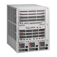
Nortel Passport 8000 Series Installing And Maintaining (112 pages)
Brand:
Nortel
| Category:
Network Hardware
| Size: 2.54 MB
Table of Contents
Table of Contents
9
Preface
17
Before You Begin
17
Text Conventions
18
Hard-Copy Technical Manuals
18
How to Get Help
19
Passport 8000 Series Chassis Hardware Components
21
8010 Chassis
21
8010Co Chassis
22
8010 Chassis
23
Figure 1 8010Co Chassis and Components
23
Figure 2 8010 Chassis and Components
24
8006 Chassis
25
8003 Chassis
26
Figure 3 8006 Chassis and Components
26
Power Supplies
27
Figure 4 8003 Chassis and Components
27
Fan Trays
28
Table 1 Number of Fan Trays Installed each Chassis
28
Installing the 8010, 8006, and 8003 Chassis
29
Preparing to Install the 8010, 8006, and 8003 Chassis
29
Shipment Contents
30
Table 2 Chassis Shipping Accessories: 8010, 8006, 8003
30
Figure 5 Items in the 8010 Chassis Shipping Container
31
Figure 6 Items in the 8006 Chassis Shipping Container
32
Supplying Equipment
33
Management Console
33
Figure 7 Items in the 8003 Chassis Shipping Container
33
Cables
34
Hardware for Mounting the 8010, 8006, 8003 Chassis in an Equipment Rack
34
Site Requirements
34
Space Requirements
34
AC Input Electrical Requirements (8010, 8006 and 8003 Chassis)
35
DC Input Electrical Requirements (8010 and 8006 Chassis)
35
Table 3 Wall Receptacle Requirements for AC Power
35
Table 4 Electrical Requirements for the DC Model
35
Environmental Requirements
36
Installing the Chassis
36
Table 5 Environmental Requirements
36
Positioning the 8010, 8006, and 8003 Chassis on a Flat Surface
37
Mounting the 8010, 8006, and 8003 Chassis in an Equipment Rack
37
Table 6 Chassis Weight Including Components and Cables
37
Table 7 Maximum Number of Chassis in 7-Foot Rack
38
Figure 8 Positioning the Rack-Mounting Brackets: 8010 Chassis
39
Figure 9 Positioning the Rack-Mounting Brackets: 8006 Chassis
39
Figure 10 Positioning the Rack-Mounting Brackets: 8003 Chassis
39
Figure 11 Attaching the Rack-Mounting Brackets to the Chassis: 8010 Chassis
40
Figure 12 Attaching the Rack-Mounting Brackets to the Chassis: 8006 Chassis
40
Figure 13 Attaching the Rack-Mounting Brackets to the Chassis: 8003
40
Figure 14 Aligning the Rack-Mounting Brackets with the Equipment Rack
41
Table 8 Number of Rack Units to Allocate for Chassis
41
Figure 17 Installing the 8010 Chassis in an Equipment Rack
43
Figure 18 Installing the 8006 Chassis in an Equipment Rack
43
Figure 19 Installing the 8003 Chassis in an Equipment Rack
43
Installing the Cable Guides
44
Figure 20 Loosening the Rack-Mounting Screws: 8010 Chassis
44
Figure 21 Loosening the Rack-Mounting Screws: 8006 Chassis
44
Figure 22 Loosening the Rack-Mounting Screws: 8003 Chassis
45
Figure 23 Sliding the Cable Guide Onto the Screws
45
Figure 24 Sliding the Cable Guide Onto the Screws: 8003 Chassis
45
Figure 25 Securing the Cable Guide to the Chassis: 8010 Chassis
46
Figure 26 Securing the Cable Guide to the Chassis: 8006 Chassis
46
Figure 27 Securing the Cable Guide to the Chassis: 8003 Chassis
47
Installing the 8010Co Chassis
49
Preparing to Install the 8010Co Chassis
49
Shipment Contents
50
Table 9 8010Co Chassis Shipping Accessories
50
Figure 28 Accessories in the 8010Co Chassis Shipping Container
51
Supplying Equipment
52
Cables
52
Hardware for Mounting the Chassis in an Equipment Rack
52
Management Console
52
Site Requirements
53
Space Requirements
53
AC Input Electrical Requirements
53
Table 10 Wall Receptacle Requirements for AC Power
53
DC Input Electrical Requirements
54
Environmental Requirements
54
Table 11 DC Power Requirement for BIP
54
Table 12 Environmental Requirements
54
Installing the Chassis
55
Mounting the 8010Co Chassis in a Two-Post Rack
55
Figure 29 Two 8010Co Chassis with BIP in a Two-Post Rack
56
Mounting the 8010Co Chassis in a 19-Inch Rack
57
Figure 30 Location of Handles on the 8010Co Chassis
58
Figure 31 Installing the Installation Shelf in a 19-Inch Equipment Rack
59
Figure 32 Installing the 8010Co Chassis in a 19-Inch Two-Post Rack
60
Mounting the 8010Co Chassis in a Hendry Rack
61
Figure 33 Installing the Installation Shelf in a Hendry Rack
61
Figure 34 Removing the Mounting Rails from the 8010Co Chassis
62
Figure 35 Installing the Mounting Rails for a Hendry Rack
63
Figure 36 Location of Handles on 8010Co Chassis
64
Installing the Cable Management Brackets
65
Figure 37 Installing Cable Management Brackets
66
Grounding the 8010Co Chassis
67
Figure 38 Location of 8010Co Chassis Ground Studs
67
Figure 39 Chassis and DC Power Supply Grounding Example
69
Table 13 Item Description for Chassis and DC Power Supply Grounding
70
Figure 40 Chassis and AC Power Supply Grounding Example
71
Table 14 Item Description for Chassis and AC Power Supply Grounding
72
Connecting the Ground Cables to the Rack Grounding Strip
73
Figure 41 Rack Grounding Strip Example
73
Operating the Passport 8000 Series Switch
75
Turning the Passport 8000 Series Switch on and off
76
Turning DC Power Supplies on and off
76
Figure 42 DC Power Supply Power Switch
77
Turning AC Power Supplies on and off
78
Verifying a Successful Installation
79
Configuring the Chassis to Operate in E Mode or M Mode
80
Table 15 Boot Mode at Startup
80
Resetting the Passport 8000 Series Switch
81
Figure 43 Reset Button
81
Installing Removable Flash Memory Cards
82
Figure 44 Inserting a Removeable Flash Memory Card: 8010Co Chassis
82
Removing Removable Flash Memory Cards
83
Figure 46 Removing a Removeable Flash Memory Card: 8010Co Chassis
83
Protecting Memory Card Files
84
Figure 47 Removing a Removeable Flash Memory Card: 8010, 8006, 8003 Chassis
84
Replacing an Air Filter (8010Co Chassis Only)
85
Figure 48 Memory Card Read-Write Protect Switch
85
Removing and Inserting an Air Filter (8010Co Chassis Only)
86
Table 16 8010Co Air Filter Physical Specifications
86
Figure 49 Inserting an Air Filter into the 8010Co Chassis
87
Troubleshooting
88
LED Indications of Problems
88
Table 17 LED Problem Indicators
88
Apparent Module Failure
89
Module Failure Workaround 1
89
Module Failure Workaround 2
90
Failure to Get a Login Prompt from the Console Port
90
Figure 50 DCE/DTE Switch
90
Cable Connection Problems
91
10BASE-T Cables
91
100BASE-T and 1000BASE-T Cables
92
8100 Series Fiber MDA Cables
92
GBIC Cables
92
Autonegotiation Mode Problems for Passport 8100 Modules
92
Technical Specifications for the Passport 8000 Series Chassis
95
8010Co Chassis
95
Physical Specifications
96
Network Equipment Building Standard
96
Environmental Specifications
96
Maximum Airflow
97
8004AC Power Supply Specifications
97
8004DC Power Supply Specifications
97
System Power Specifications
98
International Regulatory Requirements
98
Electromagnetic Emissions
98
Electromagnetic Immunity
99
Safety Agency Certification
99
8010 Chassis
99
Physical Specifications
100
Environmental Specifications
100
8004AC-DC Power Supply Specifications
101
8004DC-DC Power Supply Specifications
101
System Power Specifications
102
International Regulatory Requirements
102
Electromagnetic Emissions
102
Electromagnetic Immunity
103
Safety Agency Certification
103
8006 Chassis
103
Physical Specifications
104
Environmental Specifications
104
8004AC Power Supply Specifications
105
8004DC Power Supply Specifications
105
System Power Specifications
106
International Regulatory Requirements
106
Electromagnetic Emissions
106
Electromagnetic Immunity
107
Safety Agency Certification
107
8003 Chassis
107
Physical Specifications
108
Environmental Specifications
108
8003ACPS Power Supply Specifications
109
System Power Specifications
109
International Regulatory Requirements
109
Electromagnetic Emissions
110
Electromagnetic Immunity
110
Safety Agency Certification
110
Index
111
Advertisement
Advertisement
Related Products
Nortel Call Pilot 1.07
Nortel PeriProducer CTI Toolkit
Nortel Peri-IPML V2.1
Nortel Passport 8000 Chassis
Nortel Passport 8006
Nortel Passport 8010
Nortel Passport 8000
Nortel Passport ARN Routers
Nortel Passport 1100
Nortel Passport 15000
Nortel Categories
IP Phone
Telephone
Switch
Software
Server
More Nortel Manuals
Login
Sign In
OR
Sign in with Facebook
Sign in with Google
Upload manual
Upload from disk
Upload from URL