Nortel Passport 8000 Series Installing And Maintaining
Hide thumbs
Also See for Passport 8000 Series:
- Configuring (226 pages) ,
- Installing and maintaining (120 pages)

Related Manuals for Nortel Passport 8000 Series


Summary of Contents for Nortel Passport 8000 Series
- Page 1 Part No. 316314-D Rev 00 May 2004 4655 Great America Parkway Santa Clara, CA 95054 Installing and Maintaining the Passport 8000 Series Chassis *316314-D_Rev_00*...
- Page 2 In the interest of improving internal design, operational function, and/or reliability, Nortel Networks Inc. reserves the right to make changes to the products described in this document without notice. Nortel Networks Inc. does not assume any liability that may occur due to the use or application of the product(s) or circuit layout(s) described herein.
- Page 3 CE marking statement (Europe only) EN 55 022 statements This is to certify that the Nortel Networks 8000 Series chassis and components installed within the chassis are shielded against the generation of radio interference in accordance with the application of Council Directive 89/336/EEC.
- Page 4 BSMI statement for 8010, 8006 and 8003 chassis (Taiwan only) This is a Class A product based on the standard of the Bureau of Standards, Metrology and Inspection (BSMI) CNS 13438, Class A. MIC notice for 8010, 8006, 8003 chassis (Republic of Korea only) This device has been approved for use in Business applications only per the Class A requirements of the Republic of Korea Ministry of Information and Communications (MIC).
- Page 5 EN 60 950 statement This is to certify that the Nortel Networks 8000 Series chassis and components installed within the chassis are in compliance with the requirements of EN 60 950 in accordance with the Low Voltage Directive. Additional national differences for all European Union countries have been evaluated for compliance.
- Page 6 30 days of purchase to obtain a credit for the full purchase price. “Software” is owned or licensed by Nortel Networks, its parent or one of its subsidiaries or affiliates, and is copyrighted and licensed, not sold. Software consists of machine-readable instructions, its components, data, audio-visual content (such as images, text, recordings or pictures) and related licensed materials including all whole or partial copies.
- Page 7 (for DoD entities). Customer may terminate the license at any time. Nortel Networks may terminate the license if Customer fails to comply with the terms and conditions of this license. In either event, upon termination, Customer must either return the Software to Nortel Networks or certify its destruction.
- Page 8 316314-D Rev 00...
-
Page 9: Table Of Contents
Chapter 1 Passport 8000 Series Chassis hardware components....21 8010co chassis ............22 8010 chassis . - Page 10 Resetting the Passport 8000 Series switch ....... . . 81...
- Page 11 Appendix A Technical specifications for the Passport 8000 Series Chassis ..95 8010co Chassis ............95 Physical specifications .
- Page 12 12 Contents 8004DC-DC power supply specifications ......101 System power specifications ........102 International regulatory requirements .
- Page 13 Securing the cable guide to the chassis: 8006 Chassis ....46 Figure 27 Securing the cable guide to the chassis: 8003 Chassis ....47 Installing and Maintaining the Passport 8000 Series Chassis...
- Page 14 Figures Figure 28 Accessories in the 8010co Chassis shipping container ....51 Figure 29 Two 8010co Chassis with BIP in a two-post rack ....56 Figure 30 Location of handles on the 8010co chassis .
- Page 15 LED problem indicators ........88 Installing and Maintaining the Passport 8000 Series Chassis...
- Page 16 Tables 316314-D Rev 00...
-
Page 17: Preface
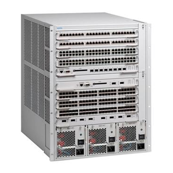
Preface The Nortel Networks* 8000 Series chassis provides the physical framework for the 8000 Series switch modules. When switch modules are installed in the chassis, the resulting network switch provides a range of data speeds and high-performance switching and routing features. -
Page 18: Text Conventions
Preface Text conventions This guide uses the following text conventions: Indicates command names and options and text that bold Courier text you need to enter. Example: Use the command. dinfo Example: Enter show ip {alerts|routes} italic text Indicates new terms, book titles, and variables in command syntax descriptions. -
Page 19: How To Get Help
Preface 19 How to get help If you purchased a service contract for your Nortel Networks product from a distributor or authorized reseller, contact the technical support staff for that distributor or reseller for assistance. If you purchased a Nortel Networks service program, contact Nortel Networks Technical Support. - Page 20 Preface 316314-D Rev 00...
-
Page 21: Passport 8000 Series Chassis Hardware Components
Passport 8000 Series Chassis hardware components Each Passport 8000 series chassis consists of a sheet metal enclosure, a backplane, and a power backplane. The number of bays for power supplies and the number of fan trays depends on the chassis type. -
Page 22: 8010Co Chassis
8692SF switch fabric modules. Slots are numbered from left to right. You can install Passport 8600 interface modules in slots 1 through 4 and slots 7 through 10. Slots 5 and 6 are reserved for Passport 8000 Series switch fabric modules. For complete information about Passport 8600 modules and instructions for installing them, see Installing Passport 8600 Switch Modules. -
Page 23: 8010 Chassis
You can install either Passport 8100 or 8600 interface modules in slots 1 through 4 and slots 7 through 10. Slots 5 and 6 are reserved for Passport 8000 Series switch fabric or switch management modules. Installing and Maintaining the Passport 8000 Series Chassis... -
Page 24: Figure 2 8010 Chassis And Components
2 serves as a clock source for the entire chassis. Therefore, you must install a 8100 series module in either slot 1 or 2 to avoid traffic loss. Note: Passport 8000 Series software Release 3.2 and later does not support configurations of Passport 8100 modules and Passport 8600 modules concurrently within the same chassis. -
Page 25: 8006 Chassis
2 serves as a clock source for the entire chassis. Therefore, you must install a Passport 8100 series module in either slot 1 or 2 to avoid traffic loss. Note: Passport 8000 Series software Release 3.2 and later does not support configurations of Passport 8100 modules and Passport 8600 modules concurrently within the same chassis. -
Page 26: 8003 Chassis
26 Chapter 1 Passport 8000 Series Chassis hardware components Figure 3 8006 Chassis and components Fan tray 8000 Series modules Power supplies 10931EA 8003 chassis The 8003 Chassis provides two slots for installing Passport 8600 interface modules and one slot for installing a 8691SF Switch Fabric Module. -
Page 27: Power Supplies
Chapter 1 Passport 8000 Series Chassis hardware components 27 Figure 4 8003 Chassis and components Fan tray 8600 Series modules Power supplies 10932EA Power supplies The 8010co, 8010, and 8006 chassis each provide three bays for installing power supplies. The following power supplies are available for these chassis: •... -
Page 28: Fan Trays
Installing an AC Power Supply in an 8000 Series Switch and Installing a DC Power Supply in an 8000 Series Switch. Fan trays Table 1 lists the number of fan trays for each Passport 8000 Series chassis. Table 1 Number of fan trays installed each chassis Chassis Fan tray 8010co Two fan trays;... -
Page 29: Installing The 8010, 8006, And 8003 Chassis
You have the cables, tools, and other equipment that you need. • Your installation site meets the physical, electrical, and environmental requirements described in “Site requirements” on page The sections that follow provide information to help you prepare for installation. Installing and Maintaining the Passport 8000 Series Chassis... -
Page 30: Shipment Contents
30 Chapter 2 Installing the 8010, 8006, and 8003 Chassis Shipment contents Inspect all items for shipping damage. If you detect any damage, do not install the chassis. Call the Nortel Networks Technical Solutions Center in your area (see “How to get help” on page 19.) In addition to the 8010, 8006 or 8003 Chassis, your shipping container contains several hardware accessories. -
Page 31: Figure 5 Items In The 8010 Chassis Shipping Container
1 = Cable adapter 2 = Rack mounting brackets 3 = Console cable 4 = Screws (x14) for brackets 5 = Screws (x24) for equipment rack 6 = Cable guides 7 = Rubber footpads 9073FB Installing and Maintaining the Passport 8000 Series Chassis... -
Page 32: Figure 6 Items In The 8006 Chassis Shipping Container
32 Chapter 2 Installing the 8010, 8006, and 8003 Chassis Figure 6 Items in the 8006 Chassis shipping container Rubber footpads 1 = Cable adapter 2 = Rack mounting brackets 3 = Console cable 4 = Screws (x10) for brackets 5 = Screws (x10) for equipment rack 6 = Cable guide 7 = Rubber footpads... -
Page 33: Supplying Equipment
PC, laptop, VT-100 console or equivalent, such as a PC terminal emulator. Or, you can attach an AT-compatible modem to allow dial-in access to startup configuration and diagnostics. Installing and Maintaining the Passport 8000 Series Chassis... -
Page 34: Cables
Ensure that the installation site meets the space, electrical, and environmental requirements listed in this section. See Appendix A, “Technical specifications for the Passport 8000 Series Chassis,” on page 95 for more information. Space requirements The installation site must provide sufficient free space around the chassis to ensure proper ventilation and access for servicing. -
Page 35: Ac Input Electrical Requirements (8010, 8006 And 8003 Chassis)
The installation site must meet the following electrical requirements for AC power (Table 3). For additional electrical requirements, see Appendix A, “Technical specifications for the Passport 8000 Series Chassis,” on page Table 3 Wall receptacle requirements for AC power Country Receptacle... -
Page 36: Environmental Requirements
36 Chapter 2 Installing the 8010, 8006, and 8003 Chassis Environmental requirements The installation site must meet the following environmental requirements (Table Table 5 Environmental requirements Altitude Humidity Temperature 0-10,000 ft (0-3048 m) 5%-85%, noncondensing 32°F-104°F (0°C-40°C), stable Installing the chassis When you are ready to install the chassis, you can do one of the following: •... -
Page 37: Positioning The 8010, 8006, And 8003 Chassis On A Flat Surface
The rubber feet are optional but recommended to keep the unit from slipping. Attach all devices to the ports. Mounting the 8010, 8006, and 8003 chassis in an equipment rack To mount the chassis in an equipment rack, you need the following items: Installing and Maintaining the Passport 8000 Series Chassis... -
Page 38: Table 7 Maximum Number Of Chassis In 7-Foot Rack
38 Chapter 2 Installing the 8010, 8006, and 8003 Chassis • Standard 19 in. (48.2 cm) equipment rack Note: If you are mounting the chassis in a 23-inch equipment rack, refer to the rack manufacturer’s 19-inch-to-23-inch rack adapter installation instructions. •... -
Page 39: Figure 8 Positioning The Rack-Mounting Brackets: 8010 Chassis
Figure 9 Positioning the rack-mounting brackets: 8006 Chassis 11151FA Figure 10 Positioning the rack-mounting brackets: 8003 Chassis 10236FA Insert and tighten the supplied flat-head screws to fasten each bracket to the chassis (Figure Figure 12, and Figure 13). Installing and Maintaining the Passport 8000 Series Chassis... -
Page 40: Figure 11 Attaching The Rack-Mounting Brackets To The Chassis: 8010 Chassis
40 Chapter 2 Installing the 8010, 8006, and 8003 Chassis Figure 11 Attaching the rack-mounting brackets to the chassis: 8010 Chassis 9104FA Figure 12 Attaching the rack-mounting brackets to the chassis: 8006 Chassis 9418FA Figure 13 Attaching the rack-mounting brackets to the chassis: 8003 10237FA 316314-D Rev 00... -
Page 41: Figure 14 Aligning The Rack-Mounting Brackets With The Equipment Rack
It is easiest to complete this step with two people. Make sure that the hole pairs on either side of the vertical support match horizontally (Figure Figure 15, and Figure 16). Figure 14 Aligning the rack-mounting brackets with the equipment rack: 8010 Chassis 9074FA Installing and Maintaining the Passport 8000 Series Chassis... - Page 42 42 Chapter 2 Installing the 8010, 8006, and 8003 Chassis Figure 15 Aligning the rack-mounting brackets with the equipment rack: 8006 Chassis 9419FA Figure 16 Aligning the rack-mounting brackets with the equipment rack: 8003 Chassis 10238FA Insert and tighten the rack-mounting screws with a Phillips screwdriver (Figure Figure 18, and...
-
Page 43: Figure 17 Installing The 8010 Chassis In An Equipment Rack
Figure 17 Installing the 8010 Chassis in an equipment rack 9075FA Figure 18 Installing the 8006 Chassis in an equipment rack 9420FA Figure 19 Installing the 8003 Chassis in an equipment rack 10239FA Installing and Maintaining the Passport 8000 Series Chassis... -
Page 44: Installing The Cable Guides
44 Chapter 2 Installing the 8010, 8006, and 8003 Chassis Installing the cable guides The cable guides keep cable clusters fastened and out of the way, but still accessible for maintenance. To install the cable guides: Loosen, but do not remove, the rack-mounting screws needed to install one cable guide (Figure Figure 21... -
Page 45: Figure 22 Loosening The Rack-Mounting Screws: 8003 Chassis
Slide the guide onto the loosened screws (Figure Figure 24). Figure 23 Sliding the cable guide onto the screws 9106FA Figure 24 Sliding the cable guide onto the screws: 8003 Chassis 10246FA Installing and Maintaining the Passport 8000 Series Chassis... -
Page 46: Figure 25 Securing The Cable Guide To The Chassis: 8010 Chassis
46 Chapter 2 Installing the 8010, 8006, and 8003 Chassis Tighten the screws to secure the guide to the chassis (Figure Figure Figure 27). Figure 25 Securing the cable guide to the chassis: 8010 Chassis 9107FA Figure 26 Securing the cable guide to the chassis: 8006 Chassis 9422FA 316314-D Rev 00... -
Page 47: Figure 27 Securing The Cable Guide To The Chassis: 8003 Chassis
Chapter 2 Installing the 8010, 8006, and 8003 Chassis 47 Figure 27 Securing the cable guide to the chassis: 8003 Chassis 10247FA Installing and Maintaining the Passport 8000 Series Chassis... - Page 48 48 Chapter 2 Installing the 8010, 8006, and 8003 Chassis 316314-D Rev 00...
-
Page 49: Installing The 8010Co Chassis
You have the cables, tools, and other equipment that you need. • Your installation site meets the physical, electrical, and environmental requirements. The sections that follow provide information to help you prepare for installation. Installing and Maintaining the Passport 8000 Series Chassis... -
Page 50: Shipment Contents
50 Chapter 3 Installing the 8010co Chassis Shipment contents Inspect all items for shipping damage. If you detect any damage, do not install the 8010co Chassis. Call the Nortel Networks Technical Solutions Center in your area (see “How to get help” on page 19). -
Page 51: Figure 28 Accessories In The 8010Co Chassis Shipping Container
7 = Side cable management brackets (x 2) standard 19-inch rack (x 16) 8 = Antistatic wrist strap 9 = Hex nuts for mounting installation shelf in a standard 19-inch rack (x4) 10452FB Installing and Maintaining the Passport 8000 Series Chassis... -
Page 52: Supplying Equipment
52 Chapter 3 Installing the 8010co Chassis Supplying equipment You might need items that are not included in the 8010co Chassis accessory package. Before installing the 8010co hardware, ensure that you have all the cables, tools, and other equipment that you need. Cables Unless you specifically ordered them, the cables required for your network configuration are not included in the 8010co Chassis accessory package. -
Page 53: Site Requirements
Ensure that the installation site meets the space, electrical, and environmental requirements listed in this section. See Appendix A, “Technical specifications for the Passport 8000 Series Chassis,” on page 95 for more information. Space requirements The installation site must provide sufficient free space around the 8010co Chassis to ensure proper ventilation and access for servicing. -
Page 54: Dc Input Electrical Requirements
54 Chapter 3 Installing the 8010co Chassis DC input electrical requirements If you are installing a BIP, the installation site must meet the following electrical requirements for DC power (Table 11). Table 11 DC power requirement for BIP Nominal input voltage Maximum input current Physical –48 /–60 VDC... -
Page 55: Installing The Chassis
Hendry rack. In a 7-foot two-post rack, you can install two 8010co Chassis platforms and a BIP. Figure 29 shows two 8010co Chassis with a BIP installed in a two-post rack. Installing and Maintaining the Passport 8000 Series Chassis... -
Page 56: Figure 29 Two 8010Co Chassis With Bip In A Two-Post Rack
56 Chapter 3 Installing the 8010co Chassis Figure 29 Two 8010co Chassis with BIP in a two-post rack 1 = Breaker interface panel 2 = 8010co Chassis (upper shelf position) 3 = 8010co Chassis (lower shelf position) 10404EC 316314-D Rev 00... -
Page 57: Mounting The 8010Co Chassis In A 19-Inch Rack
Using the chassis handles shown in Figure 30, lift the 8010co Chassis onto the installation shelf. Warning: It requires three people to lift the 8010co Chassis. You must remove the I/O modules and power supplies before lifting. Installing and Maintaining the Passport 8000 Series Chassis... -
Page 58: Figure 30 Location Of Handles On The 8010Co Chassis
58 Chapter 3 Installing the 8010co Chassis Figure 30 Location of handles on the 8010co chassis Fa il Pa ss Fa il Pa ss Chassis Handles (x4) 10737FA Holding the 8010co Chassis in position, align the flanged end of the chassis mounting rail with six holes on each side of the vertical rack support (Figure 32). -
Page 59: Figure 31 Installing The Installation Shelf In A 19-Inch Equipment Rack
Figure 31 Installing the installation shelf in a 19-inch equipment rack 1 = Phillips head screws (x4) 2 = Standard 19-inch equipment rack 3 = Nuts (x4) 4 = Installation shelf 10403FB Installing and Maintaining the Passport 8000 Series Chassis... -
Page 60: Figure 32 Installing The 8010Co Chassis In A 19-Inch Two-Post Rack
60 Chapter 3 Installing the 8010co Chassis Figure 32 Installing the 8010co Chassis in a 19-inch two-post rack Fa il Pa ss Fa il Pa ss 10225FA 316314-D Rev 00... -
Page 61: Mounting The 8010Co Chassis In A Hendry Rack
3 = Hendry equipment rack 10402FB Tighten each screw with a nutdriver. Using a Phillips screwdriver, remove the 5 screws securing each of the two mounting rails to the 8010co Chassis (Figure 34). Installing and Maintaining the Passport 8000 Series Chassis... -
Page 62: Figure 34 Removing The Mounting Rails From The 8010Co Chassis
62 Chapter 3 Installing the 8010co Chassis Figure 34 Removing the mounting rails from the 8010co Chassis Fa il Pa ss Fa il Pa ss 10417FA 316314-D Rev 00... -
Page 63: Figure 35 Installing The Mounting Rails For A Hendry Rack
Figure 35 Installing the mounting rails for a Hendry rack Fa il Pa ss Fa il Pa ss 10418FA If the holes in the rack’s vertical supports require clipnuts, insert a clipnut in 12 locations. Installing and Maintaining the Passport 8000 Series Chassis... -
Page 64: Figure 36 Location Of Handles On 8010Co Chassis
64 Chapter 3 Installing the 8010co Chassis Using the chassis handles shown in Figure 36, lift the 8010co Chassis onto the installation shelf. Warning: It requires three people to lift the 8010co Chassis. You must remove the interface modules and power supplies before lifting Figure 36 Location of handles on 8010co chassis Fa il Pa ss... -
Page 65: Installing The Cable Management Brackets
(Figure 37). To install the two side cable management brackets: Align the slots on the side bracket with the rods in the chassis (Figure 37). Push the bracket into place. Installing and Maintaining the Passport 8000 Series Chassis... -
Page 66: Figure 37 Installing Cable Management Brackets
66 Chapter 3 Installing the 8010co Chassis Figure 37 Installing cable management brackets Fa il Pa ss Fa il Pa ss 1 = Top cable management bracket 2 = Side cable management brackets (x2) 10217FB 316314-D Rev 00... -
Page 67: Grounding The 8010Co Chassis
Chapter 3 Installing the 8010co Chassis 67 Grounding the 8010co chassis Before you connect power cables or network cables to your switch, Nortel Networks recommends that you ground the 8010co chassis. Figure 38 shows the location of the ground studs on the 8010co chassis rear panel. - Page 68 68 Chapter 3 Installing the 8010co Chassis To attach a ground to one of the chassis grounding studs, you need the following: • One single-hole cable lug that fits over one of the grounding studs • Nut and a locking washer for the grounding stud. •...
-
Page 69: Figure 39 Chassis And Dc Power Supply Grounding Example
Gnd PS 2 lower Gnd PS 3 lower + DC + DC + DC + DC Gnd lower shelf – DC – DC – DC – DC Legend: = Chassis ground = Earth ground 10761EA Installing and Maintaining the Passport 8000 Series Chassis... -
Page 70: Table 13 Item Description For Chassis And Dc Power Supply Grounding
70 Chapter 3 Installing the 8010co Chassis Table 13 Item description for chassis and DC power supply grounding Item Description Cabinet frame or equipment rack AWG#6 ground lead (provided with BIP) Upper shelf chassis ground stud. Upper shelf ground lead (not provided). Upper shelf power supply ground leads x 3. -
Page 71: Figure 40 Chassis And Ac Power Supply Grounding Example
Figure 40 Chassis and AC power supply grounding example Upper shelf PS 1 PS 2 PS 3 Lower shelf PS 1 PS 2 PS 3 Legend: = Chassis ground = Earth ground 10759FA Installing and Maintaining the Passport 8000 Series Chassis... -
Page 72: Table 14 Item Description For Chassis And Ac Power Supply Grounding
72 Chapter 3 Installing the 8010co Chassis Table 14 Item description for chassis and AC power supply grounding Item Description Cabinet frame or equipment rack Upper shelf chassis ground stud Upper shelf ground leads (not provided) Lower shelf chassis ground stud Upper shelf ground leads (not provided) AC equipment ground (ACEG) leads within individual lower shelf cords (x 3) -
Page 73: Connecting The Ground Cables To The Rack Grounding Strip
Use a 7/16-inch hex wrench to fasten the hardware in the correct order. Figure 41 Rack grounding strip example 1 = Hex head bolt 3 = Ground crimp lug 2 = Lock washer 4 = Rack grounding strip 10433FA Installing and Maintaining the Passport 8000 Series Chassis... - Page 74 74 Chapter 3 Installing the 8010co Chassis 316314-D Rev 00...
-
Page 75: Operating The Passport 8000 Series Switch
Series switch and provides troubleshooting information. It includes the following topics: Topic Page Turning the Passport 8000 Series switch on and off Verifying a successful installation Configuring the chassis to operate in E mode or M mode Resetting the Passport 8000 Series switch... -
Page 76: Turning The Passport 8000 Series Switch On And Off
76 Chapter 4 Operating the Passport 8000 Series switch Turning the Passport 8000 Series switch on and off If the Passport 8000 Series Chassis has one or more DC power supplies, go to the next section, “Turning DC power supplies on and off.”... -
Page 77: Figure 42 Dc Power Supply Power Switch
Note: The fan tray red fail LED may light briefly while the fans are powering to operational speed. After you turn on the Passport 8000 Series switch, each module automatically initiates a diagnostic test to verify proper module function (see “Verifying a... -
Page 78: Turning Ac Power Supplies On And Off
Turning AC power supplies on and off To turn on a Passport 8000 Series switch with an AC power supply: Verify that the AC power cords are connected to AC power outlets. Turn the power switch on each AC power supply to the on position. Do not operate the 8010co Chassis with only one power supply. -
Page 79: Verifying A Successful Installation
Verifying a successful installation In a normal power-up sequence, the LEDs light as follows: When power is applied to the Passport 8000 Series switch, the green LED on each power supply and fan tray turns on, and the Online LED for each module lights amber. -
Page 80: Configuring The Chassis To Operate In E Mode Or M Mode
80 Chapter 4 Operating the Passport 8000 Series switch Configuring the chassis to operate in E mode or M mode The Passport 8600 system has two modes of operation: E mode and M mode. E mode is the default mode and supports up to 32,000 table entries in the system M mode supports up to 128,000 table entries in the system. -
Page 81: Resetting The Passport 8000 Series Switch
8190SM • 8691SF • 8692SF To warm-start the Passport 8000 Series switch (no diagnostic tests are run), press the Reset button for less than 5 seconds. Figure 43 shows the location of the Reset button. Figure 43 Reset button Console... -
Page 82: Installing Removable Flash Memory Cards
82 Chapter 4 Operating the Passport 8000 Series switch Installing removable flash memory cards To install a removable flash memory card in a 8190SM Module, 8691SF Module, or 8692SF Module: Position the card with the label facing to the left and the insert arrow pointing... -
Page 83: Removing Removable Flash Memory Cards
Chapter 4 Operating the Passport 8000 Series switch 83 Insert the card into the card receptacle. Gently push the card in until it fits snugly in place. Removing removable flash memory cards To remove removable flash memory cards from the 8190SM Module, the 8691SF... -
Page 84: Protecting Memory Card Files
Note: You typically do not operate a Passport 8000 Series switch with a write-protected memory card. You should make a copy of your configuration on another memory card, write-protect that card, and store it in a safe place. -
Page 85: Replacing An Air Filter (8010Co Chassis Only)
Chapter 4 Operating the Passport 8000 Series switch 85 b Pull the card out of the card receptacle. Caution: You must remove the card from the Passport 8000 Series chassis before changing the read-write protection. Failure to remove the card may result in improper write protection. -
Page 86: Removing And Inserting An Air Filter (8010Co Chassis Only)
Depth 46.27 cm (18.22 in.) Nortel Networks recommends that you replace the air filter every three months. After you install the first 8010co Chassis at your site, inspect the air filter monthly until you can establish an average period of replacement. -
Page 87: Figure 49 Inserting An Air Filter Into The 8010Co Chassis
Chapter 4 Operating the Passport 8000 Series switch 87 Remove the installed air filter from its housing and set it aside. If dust is visible on it, move it to another area to prevent dust re-contamination. Hold the new filter by its short sides with the airflow indicator pointing up and... -
Page 88: Troubleshooting
88 Chapter 4 Operating the Passport 8000 Series switch Troubleshooting The following sections provide troubleshooting information for some of the more common problems that you may encounter with the Passport 8000 Series switch. Topic Page LED indications of problems Apparent module failure... -
Page 89: Apparent Module Failure
Chapter 4 Operating the Passport 8000 Series switch 89 Table 17 LED problem indicators (continued) Symptom Probable cause Corrective action The Master LED on a The module has detected a Replace the module; make sure that it is in the... -
Page 90: Module Failure Workaround 2
Remove the faulty module. Insert a new module. Reboot the chassis. If the module still fails to operate, contact the Nortel Networks Technical Solutions Center for assistance. Failure to get a login prompt from the Console port If you connect a terminal to the Console port of the 8190SM Module, 8691SF Module, or 8692SF Module and you fail to get a login prompt, the port may have an incorrect DCE/DTE setting. -
Page 91: Cable Connection Problems
Cabling for 10BASE-T networks can consist of two-pair Category 3, 4, or 5 unshielded twisted pair (UTP) wiring. However, to prepare for future upgrades to Fast Ethernet, Nortel Networks strongly recommends that you use all Category 5 cable in your network. -
Page 92: 100Base-T And 1000Base-T Cables
8100 Series fiber MDA cables The 8100 Series fiber MDAs use only multimode 62.5/125 µm fiber cable. The Nortel Networks 100BASE-FX MDA is not supported on single-mode fiber. SC connectors are used on 2-port 100BASE-FX MDAs, and MT-RJ connectors are used on 4-port 100BASE-FX MDAs. - Page 93 Chapter 4 Operating the Passport 8000 Series switch 93 • If the autonegotiation feature is not present or is not enabled at the connected station, the Passport 8100 module may not be able to determine the correct duplex mode. In both situations, the Passport 8100 module autosenses the speed of the connected station and, by default, reverts to half-duplex mode.
- Page 94 94 Chapter 4 Operating the Passport 8000 Series switch 316314-D Rev 00...
-
Page 95: Technical Specifications For The Passport 8000 Series Chassis
Appendix A Technical specifications for the Passport 8000 Series Chassis This appendix lists the specifications for the Passport 8000 Series Chassis and includes the following topics: This appendix includes the following topics: Topic Page 8010co Chassis 8010 Chassis 8006 Chassis... -
Page 96: Physical Specifications
96 Appendix A Technical specifications for the Passport 8000 Series Chassis Physical specifications The following physical specifications apply to the 8010co chassis: Specification Parameter Height: 35 in. (88.9 cm) Rack units (RUs) Width: 19 in (48.26 cm) Depth: 23.7 in. (60.19 cm) -
Page 97: Maximum Airflow
Appendix A Technical specifications for the Passport 8000 Series Chassis 97 Maximum airflow The maximum airflow specification for the 8010co chassis is 330 linear ft/min. 8004AC power supply specifications The specifications for the 8004AC power supply are as follows: Parameter... -
Page 98: System Power Specifications
98 Appendix A Technical specifications for the Passport 8000 Series Chassis System power specifications The following system power specifications apply to the 8010co chassis: Parameter With: 8004AC-DC power With: 8004DC-DC power Input voltage: 100-240 VAC -48/-60 VDC Input current: 3 x 12 - 6 A... -
Page 99: Electromagnetic Immunity
Appendix A Technical specifications for the Passport 8000 Series Chassis 99 Electromagnetic immunity The 8010co chassis conforms to the following electromagnetic immunity standards: Parameter Specification Global basis for certification: CISPR 24:1997 Europe: EN 55024:1998 Safety agency certification The 8010co chassis conforms to the following safety agency standards:... -
Page 100: Physical Specifications
100 Appendix A Technical specifications for the Passport 8000 Series Chassis Physical specifications The following physical specifications apply to the 8010 chassis: Parameter Specification Height: 22.9 in. (58.2 cm) Width: 17.5 in. (44.5 cm) Depth: 19.9 in. (50.5 cm) Weight (empty):... -
Page 101: 8004Ac-Dc Power Supply Specifications
Appendix A Technical specifications for the Passport 8000 Series Chassis 101 8004AC-DC power supply specifications The specifications for the 8004AC-DC power supply are as follows: Parameter Specification Input voltage: 100 to 240 VAC Input frequency: 47 to 63 Hz Input current:... -
Page 102: System Power Specifications
102 Appendix A Technical specifications for the Passport 8000 Series Chassis System power specifications The following system power specifications apply to the 8010 chassis: Parameter With: 8004AC-DC power With: 8004DC-DC power Input voltage: 100-240 VAC -48/-60 VDC Input current: 3 x 12 - 6 A... -
Page 103: Electromagnetic Immunity
Appendix A Technical specifications for the Passport 8000 Series Chassis 103 Electromagnetic immunity The 8010 chassis conforms to the following electromagnetic immunity standards: Parameter Specification Global basis for certification: CISPR 24:1997 Europe: EN 55024:1998 Safety agency certification The 8010 chassis conforms to the following safety agency standards:... -
Page 104: Physical Specifications
104 Appendix A Technical specifications for the Passport 8000 Series Chassis Physical specifications The following physical specifications apply to the 8006 chassis: Parameter Specification Height: 15.8 in. (40.1 cm) Width: 17.5 in. (44.5 cm) Depth: 19.9 in. (50.5 cm) Weight (empty):... -
Page 105: 8004Ac Power Supply Specifications
Appendix A Technical specifications for the Passport 8000 Series Chassis 105 8004AC power supply specifications The specifications for the 8004AC power supply are as follows: Parameter Specification Input voltage: 100 to 240 VAC Input frequency: 47 to 63 Hz Input current:... -
Page 106: System Power Specifications
106 Appendix A Technical specifications for the Passport 8000 Series Chassis System power specifications The following system power specifications apply to the 8006 chassis: Parameter With: 8004AC power With: 8004DC power Input voltage: 100-240 VAC -48/-60 VDC Input current: 3 x 12 - 6 A... -
Page 107: Electromagnetic Immunity
Appendix A Technical specifications for the Passport 8000 Series Chassis 107 Electromagnetic immunity The 8006 chassis conforms to the following electromagnetic immunity standards: Parameter Specification Global basis for certification: CISPR 24:1997 Europe: EN 55024:1998 Safety agency certification The 8006 chassis conforms to the following safety agency standards:... -
Page 108: Physical Specifications
108 Appendix A Technical specifications for the Passport 8000 Series Chassis Physical specifications The following physical specifications apply to the 8003 chassis: Parameter Specification Height: 10.5 in. (26.7 cm) Width: 18.5 in. (47.0 cm) Depth: 19.9 in. (50.5 cm) Weight (empty):... -
Page 109: 8003Acps Power Supply Specifications
Appendix A Technical specifications for the Passport 8000 Series Chassis 109 8003ACPS power supply specifications The specifications for the 8003ACPS power supply are as follows: Parameter Specification Input voltage: 100 to 240 VAC Input frequency: 50 to 60 Hz Maximum input current: 7.8 A per power supply... -
Page 110: Electromagnetic Emissions
110 Appendix A Technical specifications for the Passport 8000 Series Chassis Electromagnetic emissions The 8006 chassis conforms to the following electromagnetic emissions standards: Specification Parameter Global basis for certification: CISPR 22-1997 Class A FCC CFR47 Part 15, Subpart B, Class A... -
Page 111: Index
34, 53 resetting 81 technical specifications 95 verifying a successful installation 79 conventions, text 18 installation crossover cable 91 flash memory card 82 preparing for 29, 49 customer support 19 Installing and Maintaining the Passport 8000 Series Chassis... - Page 112 30, 50 site requirements 34, 53 software incompatibility 88 space requirements 34, 53 specifications, technical electrical 35, 53, 54 environmental 36, 54 space 34, 53 straight-through cable 91 support, Nortel Networks 19 system log 89 316314-D Rev 00...
Need help?
Do you have a question about the Passport 8000 Series and is the answer not in the manual?
Questions and answers