Sign In
Upload
Manuals
Brands
Mitsubishi Electric Manuals
Amplifier
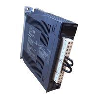
MELSERVO MR-J3-10A1
Mitsubishi Electric MELSERVO MR-J3-10A1 Manuals
Manuals and User Guides for Mitsubishi Electric MELSERVO MR-J3-10A1. We have
1
Mitsubishi Electric MELSERVO MR-J3-10A1 manual available for free PDF download: Instruction Manual
Mitsubishi Electric MELSERVO MR-J3-10A1 Instruction Manual (460 pages)
Servo Amplifier
Brand:
Mitsubishi Electric
| Category:
Amplifier
| Size: 12.75 MB
Table of Contents
Table of Contents
13
Servo Amplifier
1
Safety Instructions
2
Mr-J3-200A
12
Table of Contents
13
Functions and Configuration
22
Introduction
22
Function Block Diagram
23
Mr-J3-700A
24
Mr-J3-11Ka
25
Servo Amplifier Standard Specifications
26
Function List
28
Model Code Definition
29
Combination with Servo Motor
31
Mr-J3-15Ka
31
Structure
32
Parts Identification
32
Mr-J3-22Ka
38
Removal and Reinstallation of the
39
Configuration Including Auxiliary Equipment
42
Mr-J3-60A4
44
Installation
50
Installation Direction and Clearances
50
Keep out Foreign Materials
52
Cable Stress
52
Inspection Items
53
Parts Having Service Lives
53
Signals and Wiring
54
Input Power Supply Circuit
55
Servo Amplifier
61
I/O Signal Connection Example
63
Position Control Mode
63
Speed Control Mode
65
Torque Control Mode
66
Explanation of Power Supply System
67
Signal Explanations
67
Power-On Sequence
68
CNP1, CNP2, CNP3 Wiring Method
70
Mr-J3-100A4
70
Mr-J3-200A4
71
Mr-J3-350A4
72
Connectors and Signal Arrangements
77
Signal Explanations
80
Detailed Description of the Signals
90
Position Control Mode
90
Speed Control Mode
94
Torque Control Mode
96
Position/Speed Control Change Mode
99
Speed/Torque Control Change Mode
101
Torque/Position Control Change Mode
103
Alarm Occurrence Timing Chart
104
Interfaces
105
Internal Connection Diagram
105
Detailed Description of Interfaces
106
Source I/O Interfaces
109
Treatment of Cable Shield External Conductor
110
Connection of Servo Amplifier and Servo Motor
111
Connection Instructions
111
Power Supply Cable Wiring Diagrams
112
Servo Motor with Electromagnetic Brake
122
Safety Precautions
122
Setting
122
Timing Charts
123
Wiring Diagrams (HF-MP Series HF-KP Series Servo Motor)
125
Grounding
127
Startup
128
Switching Power on for the First Time
128
Startup Procedure
128
Wiring Check
129
Surrounding Environment
130
Startup in Position Control Mode
131
Power on and off Procedures
131
Stop
131
Test Operation
132
Parameter Setting
133
Actual Operation
133
Trouble at Start-Up
134
Startup in Speed Control Mode
136
Power on and off Procedures
136
Stop
136
Test Operation
137
Parameter Setting
138
Actual Operation
138
Trouble at Start-Up
139
Startup in Torque Control Mode
140
Power on and off Procedures
140
Stop
140
Test Operation
141
Parameter Setting
142
Actual Operation
142
Trouble at Start-Up
143
Parameters
144
Basic Setting Parameters (No.pa )
144
Parameter List
144
Parameter Write Inhibit
145
Selection of Control Mode
145
Selection of Regenerative Option
146
Using Absolute Position Detection System
147
Using Electromagnetic Brake Interlock (MBR)
147
Number of Command Input Pulses Per Servo Motor Revolution
148
Electronic Gear
149
Auto Tuning
153
In-Position Range
154
Torque Limit
155
Selection of Command Pulse Input Form
156
Selection of Servo Motor Rotation Direction
157
Encoder Output Pulse
157
Section 1
159
Gain/Filter Parameters (No. PB )
159
Parameter List
159
Detail List
160
(Advanced Vibration Suppression Control)
161
PB04 FFC Feed Forward Gain
162
PB05 for Manufacturer Setting
162
PB06 GD2 Ratio of Load Inertia Moment to Servo Motor Inertia Moment
162
PB07 PG1 Model Loop Gain 24 Rad/S
163
PB08 PG2 Position Loop Gain 37 Rad/S
163
PB09 VG2 Speed Loop Gain 823 Rad/S
163
PB10 VIC Speed Integral Compensation
163
PB11 VDC Speed Differential Compensation
163
PB12 for Manufacturer Setting
163
PB13 NH1 Machine Resonance Suppression Filter 1 4500 Hz
163
PB15 NH2 Machine Resonance Suppression Filter
163
PB17 Automatic Setting Parameter
164
PB19 VRF1 Vibration Suppression Control Vibration Frequency Setting Hz
165
Pb20 Vrf2
165
PB21 for Manufacturer Setting
165
Moment
166
PB25 *BOP1 Function Selection
166
PB27 CDL Gain Changing Condition
166
Setting
166
Position Smoothing
168
Extension Setting Parameters (No. PC )
169
Parameter List
169
List of Details
171
Analog Monitor
181
Alarm History Clear
183
Section 2
184
I/O Setting Parameters (No. PD )
184
Parameter List
184
List of Details
185
Pd01 *Dia1
185
Input Signal Automatic on Selection 1
185
Input Signal Device Selection 1 (CN1-15) 00020202H
186
Input Signal Device Selection 2 (CN1-16) 00212100H
186
Input Signal Device Selection 3 (CN1-17) 00070704H
186
Input Signal Device Selection 4 (CN1-18) 00080805H
186
Input Signal Device Selection 5 (CN1-19) 00030303H
186
Input Signal Device Selection 6 (CN1-41) 00202006H
186
Input Signal Device Selection 10 (CN1-45) 00232323H
186
Output Signal Device Selection 1 (CN1-22) 0004H
189
Output Signal Device Selection 3 (CN1-24) 0004H
189
Output Signal Device Selection 4 (CN1-25) 0007H
189
PD17 for Manufacturer Setting PD18 *DO6
190
Output Signal Device Selection 6 (CN1-49) 0002H
190
PD20 *DOP1 Function Selection
191
PD22 *DOP3 Function Selection
191
Using Forward/Reverse Rotation Stroke End to Change the Stopping Pattern
193
PD25 for Manufacturer Setting
193
Pd29 Pd30
193
Display and Operation Sections
194
Overview
194
Display Sequence
195
Status Display
196
Display Transition
196
Display Examples
197
Status Display List
198
Changing the Status Display Screen
199
Diagnostic Mode
200
Alarm Mode
202
Parameter Mode
203
Parameter Mode Transition
203
Operation Example
204
External I/O Signal Display
206
Output Signal (DO) Forced Output
209
Test Operation Mode
210
Mode Change
210
Jog Operation
211
Positioning Operation
212
Motor-Less Operation
213
General Gain Adjustment
214
Different Adjustment Methods
214
Adjustment on a Single Servo Amplifier
214
Adjustment Using MR Configurator
215
Auto Tuning
215
Auto Tuning Mode 1
215
Auto Tuning Mode Operation
217
Adjustment Procedure by Auto Tuning
218
Response Level Setting in Auto Tuning Mode
219
Manual Mode 1 (Simple Manual Adjustment)
220
Interpolation Mode
223
Differences between MELSERVO-J2-Super and MELSERVO-J3 in Auto Tuning
224
Special Adjustment Functions
226
Function Block Diagram
226
Adaptive Filter
226
Machine Resonance Suppression Filter
229
Advanced Vibration Suppression Control
231
Low-Pass Filter
235
Gain Changing Function
235
Applications
235
Function Block Diagram
236
Parameters
237
Gain Changing Operation
239
Troubleshooting
242
Alarms and Warning List
242
Remedies for Alarms
243
Remedies for Warnings
249
Outline Drawings
252
Servo Amplifier
252
Mr-J3-11Ka4
260
Connector for CN1
261
Characteristics
264
Overload Protection Characteristics
264
Power Supply Equipment Capacity and Generated Loss
266
Mr-J3-15Ka4
267
Dynamic Brake Characteristics
269
Dynamic Brake Operation
269
The Dynamic Brake at the Load Inertia Moment
271
Mr-J3-22Ka4
271
Encoder Cable Flexing Life
272
Inrush Currents at Power-On of Main Circuit and Control Circuit
273
Options and Auxiliary Equipment
274
Cable/Connector Sets
274
Combinations of Cable/Connector Sets
275
Encoder Cable/Connector Sets
282
Motor Power Supply Cables
291
Motor Brake Cables
293
Regenerative Options
302
Brake Unit
306
Power Regeneration Converter
309
Power Regeneration Common Converter
312
External Dynamic Brake
320
Junction Terminal Block MR-TB50
325
MR Configurator
327
Battery Unit MR-J3BAT
330
Heat Sink Outside Mounting Attachment (MR-J3ACN)
331
Recommended Wires
333
No-Fuse Breakers, Fuses, Magnetic Contactors
337
Power Factor Improving DC Reactor
338
Power Factor Improving Reactors
339
Relays (Recommended)
340
Surge Absorbers (Recommended)
341
Noise Reduction Techniques
341
Leakage Current Breaker
347
EMC Filter (Recommended)
349
Communication Function
354
Configuration
354
Communication Specifications
356
Communication Overview
356
Parameter Setting
357
Protocol
358
Transmission Data Configuration
358
Character Codes
359
Error Codes
360
Checksum
360
Time-Out Operation
361
Retry Operation
361
Initialization
362
Communication Procedure Example
362
Command and Data No. List
363
Read Commands
363
Write Commands
367
Detailed Explanations of Commands
369
Data Processing
369
Status Display
371
Parameters
372
External I/O Signal Statuses (DI0 Diagnosis)
375
Input Device ON/OFF
377
Disable/Enable of I/O Devices (DIO)
378
Input Devices ON/OFF (Test Operation)
378
Test Operation Mode
379
Output Signal Pin ON/OFF Output Signal (DO) Forced Output
382
Alarm History
383
Current Alarm
384
Other Commands
385
Absolute Position Detection System
386
Outline
386
Features
386
Restrictions
386
Specifications
387
Battery Installation Procedure
388
Standard Connection Diagram
389
Signal Explanation
390
Startup Procedure
391
Absolute Position Data Transfer Protocol
392
Data Transfer Procedure
392
Transfer Method
393
Home Position Setting
402
Use of Servo Motor with Electromagnetic Brake
404
How to Process the Absolute Position Data at Detection of Stroke End
405
Examples of Use
406
Melsec Fx(2N)-32Mt (Fx(2N)-1Pg)
406
Melsec A1Sd75
418
Melsec Qd75
431
Absolute Position Data Transfer Errors
440
Corrective Actions
440
Error Resetting Conditions
442
Communication-Based ABS Transfer System
443
Serial Communication Command
443
Absolute Position Data Transfer Protocol
443
Confirmation of Absolute Position Detection Data
447
Appendix
448
App 1. Parameter List
448
App 2. Signal Layout Recording Paper
450
App 3. Status Display Block Diagram
451
App 4. Change of Connector Sets to the Rohs Compatible Products
452
Advertisement
Share and save
Advertisement
Related Products
Mitsubishi Electric Melservo MR-J3-10B
Mitsubishi Electric Melservo MR-J3-100B
Mitsubishi Electric Melservo MR-J3-10B1
Mitsubishi Electric Melservo MR-J3-100B4
Mitsubishi Electric MR-J3-10T
Mitsubishi Electric MR-J3-10T1
Mitsubishi Electric MR-J3-100T
Mitsubishi Electric Melservo MR-J3-15KB
Mitsubishi Electric Melservo MR-J3-15KB4
Mitsubishi Electric Melservo MR-J3-11KB4
Mitsubishi Electric Categories
Air Conditioner
Controller
Projector
Inverter
Heat Pump
More Mitsubishi Electric Manuals
Login
Sign In
OR
Sign in with Facebook
Sign in with Google
Upload manual
Upload from disk
Upload from URL