Kollmorgen AKD PDMM series Manuals
Manuals and User Guides for Kollmorgen AKD PDMM series. We have 4 Kollmorgen AKD PDMM series manuals available for free PDF download: User Manual, Installation Manual
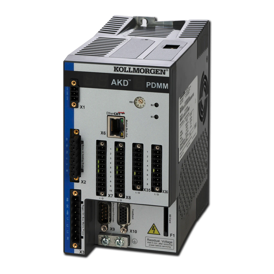
Kollmorgen AKD PDMM series User Manual (513 pages)
Brand: Kollmorgen
|
Category: Servo Drives
|
Size: 21 MB
Table of Contents
-
-
-
Motor42
-
Feedback45
-
-
Parameters46
-
Calculations47
-
Constants47
-
Current Loop47
-
-
-
Foldback47
-
Brake50
-
-
Overview53
-
-
-
-
Limits62
-
-
-
-
Grid75
-
-
-
-
Introduction87
-
Tuning Guide87
-
Overview87
-
-
-
13 Scope
103-
Overview103
-
Using the Scope103
-
-
Source Column103
-
Color Column104
-
Hide Column104
-
Y-Axis Column104
-
-
-
Trigger Position106
-
Trigger Type106
-
Trigger Value107
-
Trigger Slope109
-
-
Scope Settings109
-
-
-
Terminal115
-
Parameter List117
-
-
-
Clearing Faults151
-
Unknown Fault155
-
Remedies155
-
-
-
Motor Connection166
-
DC Bus Link (X3)169
-
I/O Connection173
-
-
Aio.iscale208
-
Aio.pscale208
-
Aio.vscale209
-
-
-
Aout.cutoff212
-
Aout.iscale212
-
Aout.mode213
-
Aout.offset214
-
Aout.pscale214
-
Aout.value215
-
Aout.valueu216
-
Aout.vscale216
-
-
-
Aout2.Cutoff219
-
Aout2.Mode219
-
Aout2.Offset220
-
Aout2.Value220
-
Aout.valueu220
-
-
-
Bode.excitegap223
-
Bode.freq223
-
Bode.iamp224
-
Bode.iflimit225
-
Bode.ifthresh226
-
Bode.injectpoint226
-
Bode.mode227
-
Bode.modetimer230
-
Bode.prbdepth231
-
Bode.vamp232
-
Bode.vflimit233
-
Bode.vfthresh234
-
-
25 CS Parameters
236-
Cs.dec237
-
Cs.state238
-
Cs.to238
-
Cs.vthresh240
-
-
-
Din.rotary243
-
Din.states244
-
-
Dout.ctrl254
-
Dout.relaymode254
-
Dout.states255
-
-
-
Drv.acc262
-
Drv.active264
-
Drv.blinkdisplay264
-
Drv.boottime265
-
Drv.clrfaulthist265
-
Drv.clrfaults266
-
Drv.cmddelay266
-
Drv.cmdsource267
-
Drv.crashdump268
-
Drv.dbilimit268
-
Drv.dec269
-
Drv.difvar270
-
Drv.dir271
-
Drv.dis272
-
Drv.dismode273
-
Drv.dissources274
-
Drv.disto275
-
Drv.emuedir276
-
Drv.emuemode277
-
Drv.emuemturn278
-
Drv.emueres280
-
Drv.emuezoffset280
-
Drv.en281
-
Drv.endefault281
-
Drv.faulthist282
-
Drv.faults283
-
Drv.handwheelsrc284
-
Drv.help284
-
Drv.helpall284
-
Drv.hwenable285
-
Drv.hwendelay285
-
Drv.hwenmode286
-
Drv.icont287
-
Drv.info287
-
Drv.ipeak288
-
Drv.izero289
-
Drv.list289
-
Drv.logicvolts289
-
Drv.memaddr290
-
Drv.memdata291
-
Drv.name291
-
Drv.nvcheck292
-
Drv.nvlist292
-
Drv.nvload293
-
Drv.nvsave293
-
Drv.ontime293
-
Drv.opmode294
-
Drv.readformat295
-
Drv.rstvar295
-
Drv.runtime296
-
Drv.setupreqbits296
-
Drv.setupreqlist297
-
Drv.stop297
-
Drv.temperatures298
-
Drv.time298
-
Drv.type299
-
Drv.ver300
-
Drv.verimage300
-
Drv.warnings301
-
Drv.zero302
-
-
-
Eip.connected304
-
Eip.posunit304
-
Eip.profunit305
-
-
Faultx.action307
-
-
-
Fb1.Bissbits309
-
Fb1.Encres309
-
Fb1.Hallstate310
-
Fb1.Hallstateu311
-
Fb1.Hallstatev311
-
Fb1.Hallstatew311
-
Fb1.Identified312
-
Fb1.Initsigned313
-
Fb1.Mechpos313
-
Fb1.Memver314
-
Fb1.Offset314
-
Fb1.Origin315
-
Fb1.P316
-
Fb1.Pfind316
-
Fb1.Pfindcmdu317
-
Fb1.Poffset317
-
Fb1.Poles318
-
Fb1.Pscale318
-
Fb1.Punit319
-
Fb1.Resktr319
-
Fb1.Resrefphase320
-
Fb1.Select320
-
Fb1.Trackingcal322
-
-
-
Fb3.Mode328
-
Fb3.P328
-
Fb3.Pdir329
-
Fb3.Poffset329
-
Fb3.Punit329
-
Advertisement
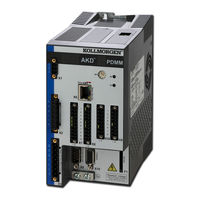
Kollmorgen AKD PDMM series Installation Manual (216 pages)
Brand: Kollmorgen
|
Category: Servo Drives
|
Size: 17 MB
Table of Contents
-
3 Safety
14 -
4 Handling
19-
Transport20
-
Packaging20
-
Storage20
-
Disassemble21
-
Disposal22
-
-
5 Approvals
23 -
6 Package
29-
Nameplate30
-
-
Fusing40
-
Connectors41
-
-
Stop53
-
-
-
-
Wiring80
-
-
-
-
-
-
Resolver124
-
Sfd125
-
Sfd3126
-
Hiperface DSL127
-
Sine Encoder134
-
Hall Sensors136
-
-
-
I/O Connection146
-
Overview146
-
-
LED Display165
-
SD Card Slot169
-
-
Pinout180
-
Bus Protocols180
-
Ethercat181
-
Synqnet182
-
Profinet182
-
Ethernet/Ip182
-
Sercos183
-
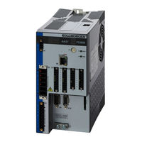
Kollmorgen AKD PDMM series Installation Manual (196 pages)
Brand: Kollmorgen
|
Category: DC Drives
|
Size: 11 MB
Table of Contents
-
2 General
10-
3 Safety
14-
Handling18
-
Packaging18
-
Storage18
-
Transport18
-
Uninstalling19
-
-
4 Approvals
20 -
5 Package
26-
Nameplate27
-
-
Fusing37
-
Connectors38
-
-
Stop50
-
-
Advertisement

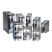
Kollmorgen AKD PDMM series Installation Manual (180 pages)
Brand: Kollmorgen
|
Category: Servo Drives
|
Size: 8 MB
Table of Contents
-
2 Safety
14 -
3 Approvals
17 -
4 Handling
24-
Transport25
-
Packaging25
-
Storage25
-
Uninstalling26
-
-
5 Package
27-
Nameplate28
-
-
103 X1030
-
104 X1031
-
Fusing37
-
Connectors38
-
-
Stop50
-
-
-