Kollmorgen AKD PDMM series User Manual
Hide thumbs
Also See for AKD PDMM series:
- Installation manual (196 pages) ,
- Installation manual (216 pages) ,
- Installation manual (180 pages)
Table of Contents
Advertisement
Quick Links
Download this manual
See also:
Installation Manual
Advertisement
Table of Contents

Related Manuals for Kollmorgen AKD PDMM series


Summary of Contents for Kollmorgen AKD PDMM series
- Page 1 AKD PDMM™ User Guide Edition December 2012, Revision B Valid for Hardware Revision DB Patents Pending Part Number 903-200016-00 Keep all manuals as a product component during the life span of the product. Pass all manuals to future users/owners of the product.
-
Page 2: Trademarks And Copyrights
All timing diagrams, whether produced by Kollmorgen or included by courtesy of the PLCopen organ- ization, are provided with accuracy on a best-effort basis with no warranty, explicit or implied, by Koll- morgen. The user releases Kollmorgen from any liability arising out of the use of these timing diagrams. Kollmorgen™ | December 2012... -
Page 3: Table Of Contents
7.1.2 Motor Setup 7.1.3 Using the Motor View 7.1.4 Selecting a Motor 7.1.4.1 Configuring Custom Motors 7.1.4.2 Validating Motor Parameters 7.2 Feedback 1 7.2.1 Overview 7.2.2 Using Feedback Options 7.2.2.1 Auto 7.2.2.2 Incremental Encoder 7.2.2.3 Sine Encoder Kollmorgen™ | December 2012... - Page 4 Setting the Capture Edge (CAP0.EDGE) Setting the Pre-Condition Event: (CAP0.EVENT) Setting up a Pre-Condition for complex capture 7.6.3 Kollmorgen Test Reports 8 Using AKD PDMM in a Vertical Axis 9 Configuring with Linear Motors 9.1 Connecting a DDL Motor to an AKD PDMM Drive 10 Configuring General Drive Settings 10.1 Limits...
- Page 5 During a change on the fly condition Movement to the same direction Movement in different directions 12 Tuning Your System 12.1 Introduction 12.2 Slider Tuning 12.2.1 Gentle, Medium, and Stiff 12.2.2 The Slider 12.2.3 Inertia Ratio 12.3 Tuning Guide Kollmorgen™ | December 2012...
- Page 6 13.3.7 Manual range per axis 13.3.8 Unit display on Y axis 14 Using Parameters and the Terminal Screen 14.1 Terminal 14.1.1 Overview 14.1.2 Using the Terminal 14.1.3 Macros Creating a Macro from Terminal commands Macro Editor 14.2 Parameter List Kollmorgen™ | December 2012...
- Page 7 17.17 Up / Down signal connection 17.17.1 Up / Down input 5 V (X9) 17.17.2 Up / Down input 24 V (X7) 17.18 Feedback Connector (X10) 18 Block Diagrams 18.1 Block Diagram for Current Loop 18.2 Block Diagram for Position/Velocity Loop Kollmorgen™ | December 2012...
- Page 8 24.2 BODE.FREQ 24.3 BODE.IAMP 24.4 BODE.IFLIMIT 24.5 BODE.IFTHRESH 24.6 BODE.INJECTPOINT 24.7 BODE.MODE 24.8 BODE.MODETIMER 24.9 BODE.PRBDEPTH 24.10 BODE.VAMP 24.11 BODE.VFLIMIT 24.12 BODE.VFTHRESH 25 CS Parameters 25.1 CS.DEC 25.2 CS.STATE 25.3 CS.TO 25.4 CS.VTHRESH 26 DIN Parameters Kollmorgen™ | December 2012...
- Page 9 28.3 DRV.BLINKDISPLAY 28.4 DRV.BOOTTIME 28.5 DRV.CLRFAULTHIST 28.6 DRV.CLRFAULTS 28.7 DRV.CMDDELAY 28.8 DRV.CMDSOURCE 28.9 DRV.CRASHDUMP 28.10 DRV.DBILIMIT 28.11 DRV.DEC 28.12 DRV.DIFVAR 28.13 DRV.DIR 28.14 DRV.DIS 28.15 DRV.DISMODE 28.16 DRV.DISSOURCES 28.17 DRV.DISSOURCESMASK 28.18 DRV.DISTO 28.19 DRV.EMUECHECKSPEED 28.20 DRV.EMUEDIR Kollmorgen™ | December 2012...
- Page 10 28.49 DRV.NVSAVE 28.50 DRV.ONTIME 28.51 DRV.OPMODE 28.52 DRV.READFORMAT 28.53 DRV.RSTVAR 28.54 DRV.RUNTIME 28.55 DRV.SETUPREQBITS 28.56 DRV.SETUPREQLIST 28.57 DRV.STOP 28.58 DRV.TEMPERATURES 28.59 DRV.TIME 28.60 DRV.TYPE 28.61 DRV.VER 28.62 DRV.VERIMAGE 28.63 DRV.WARNING1 to DRV.WARNING10 28.64 DRV.WARNINGS 28.65 DRV.ZERO Kollmorgen™ | December 2012...
- Page 11 31.25 FB1.USERDWORD0 to FB1.USERWORD1 31.26 FB1.USERWORD1 to FB1.USERWORD3 32 FB3 Parameters 32.1 FB3.MODE 32.2 FB3.P 32.3 FB3.PDIR 32.4 FB3.POFFSET 32.5 FB3.PUNIT 33 FBUS Parameters 33.1 FBUS.PARAM1 TO FBUS.PARAM10 33.2 FBUS.PLLSTATE 33.3 FBUS.PLLTHRESH 33.4 FBUS.PROTECTION 33.5 FBUS.REMOTE Kollmorgen™ | December 2012...
- Page 12 36.6 IL.FBSOURCE 36.7 IL.FF 36.8 IL.FOLDFTHRESH 36.9 IL.FOLDFTHRESHU 36.10 IL.FOLDWTHRESH 36.11 IL.FRICTION 36.12 IL.IFOLD 36.13 IL.IUFB 36.14 IL.IVFB 36.15 IL.KACCFF 36.16 IL.KBUSFF 36.17 IL.KP 36.18 IL.KPDRATIO 36.19 IL.KPLOOKUPINDEX 36.20 IL.KPLOOKUPVALUE 36.21 IL.KPLOOKUPVALUES 36.22 IL.KVFF 36.23 IL.LIMITN Kollmorgen™ | December 2012...
- Page 13 39.7 MOTOR.ICONT 39.8 MOTOR.IDDATAVALID 39.9 MOTOR.IMID 39.10 MOTOR.IMTR 39.11 MOTOR.INERTIA 39.12 MOTOR.IPEAK 39.13 MOTOR.KE 39.14 MOTOR.KT 39.15 MOTOR.LQLL 39.16 MOTOR.NAME 39.17 MOTOR.PHASE 39.18 MOTOR.PITCH 39.19 MOTOR.POLES 39.20 MOTOR.R 39.21 MOTOR.RTYPE 39.22 MOTOR.TBRAKEAPP 39.23 MOTOR.TBRAKERLS 39.24 MOTOR.TBRAKETO Kollmorgen™ | December 2012...
- Page 14 41.6 REC.OFF 41.7 REC.RECPRMLIST 41.8 REC.RETRIEVE 41.9 REC.RETRIEVEDATA 41.10 REC.RETRIEVEFRMT 41.11 REC.RETRIEVEHDR 41.12 REC.RETRIEVESIZE 41.13 REC.STOPTYPE 41.14 REC.TRIG 41.15 REC.TRIGPARAM 41.16 REC.TRIGPOS 41.17 REC.TRIGPRMLIST 41.18 REC.TRIGSLOPE 41.19 REC.TRIGTYPE 41.20 REC.TRIGVAL 42 REGEN Parameters 42.1 REGEN.POWER 42.2 REGEN.POWERFILTERED Kollmorgen™ | December 2012...
- Page 15 47.8 VBUS.VALUE 48 VL Parameters 48.1 VL.ARPF1 TO VL.ARPF4 48.2 VL.ARPQ1 TO VL.ARPQ4 48.3 VL.ARTYPE1 TO VL.ARTYPE4 48.4 VL.ARZF1 TO VL.ARZF4 48.5 VL.ARZQ1 TO VL.ARZQ4 48.6 VL.BUSFF 48.7 VL.CMD 48.8 VL.CMDU 48.9 VL.ERR 48.10 VL.FB 48.11 VL.FBFILTER Kollmorgen™ | December 2012...
- Page 16 50.9 Adjusting EtherCAT Cycle Time 50.10 Maximum Cycle Times depending on operation mode 50.11 Synchronization 50.11.1 Synchronization behavior with distributed clocks (DC) enabled 50.11.2 Synchronization behavior with distributed clocks (DC) disabled 50.12 Latch Control Word and Latch Status Word Kollmorgen™ | December 2012...
- Page 17 AKD PDMM User Guide | Table of Contents 50.13 Mailbox Handling 50.13.1 Mailbox Output 50.13.2 Mailbox Input 50.13.3 Example: Mailbox Access 50.14 Fieldbus Parameters 50.15 EEProm Content Glossary 51 Index Global Support Contacts Kollmorgen™ | December 2012...
-
Page 18: Welcome To Akd Pdmm User Guide
Check the website for the most current manuals. The documentation available on the Kollmorgen website includes the following: Related documents for the AKD PDMM series include: AKD PDMM Quick Start (also provided in hard copy). This guide provides instructions for initial drive setup and connection to a network. -
Page 19: Akd Pdmm Models
The figure below shows part number identification for drive features. Features available in the AKD PDMM are marked bold green. The customization code includes language version of printed material for European countries: D000 for German E000 for English F000 for French I000 for Italian Kollmorgen™ | December 2012... -
Page 20: Software Setup
3 Software Setup 3.1 Install and Start the KAS IDE Once the Kollmorgen Automation Suite Integrated Development Environment (KAS IDE) installation is complete, click the IDE icon to launch the program. The KVB software used for developing an HMI display does not install with the KAS IDE and must be installed separately. - Page 21 To associate the project with the IP address of the PDMM controller, right click on the Controller option in the Project View. Figure 5-3: Controller Selection Select Properties and the following screen appears: Figure 5-4: Controller Properties Type in the IP address of the PDMM, set the Controller Type to PDMM and click OK. Kollmorgen™ | December 2012...
-
Page 22: Kas Ide Project View
Click OK, to add these devices to the project. 1. Go to the EtherCAT Devices view and press Scan Devices 2. Mapped to Axis in the Application Figure 5-7: Scan Devices & Mapped to Axis The devices are added to the project view: Kollmorgen™ | December 2012... - Page 23 A set of screens will open in the work space that enable the user to completely configure the selected drive: Figure 5-11: AKD GUI screens Additionally, the setup wizard will guide you through a set of configuration steps: Figure 5-12: Setup Wizard Kollmorgen™ | December 2012...
-
Page 24: Where To Go From Here
Workbench Views (pg 29) through Using Parameters and the Terminal Screen (pg 114). For more information about programming your application and system, see the KAS IDE Online Help. The best place to start is Using KAS IDE > Creating a Project > Steps 1 - 15. Kollmorgen™ | December 2012... - Page 25 This page intentionally left blank. Kollmorgen™ | December 2012...
-
Page 26: Initial Drive Setup
AKD PDMM User Guide | 4 Initial Drive Setup 4 Initial Drive Setup 4.1 Initial Drive Setup 4.2 AKD PDMM Setup Wizard Kollmorgen™ | December 2012... -
Page 27: Initial Drive Setup
1. Access the Setup Wizard by double-clicking on the drive name in the project view. 2. Enable Online Configuration mode from the toolbar, by pressing the “Toggle Online Configuration Mode” button. Kollmorgen™ | December 2012... - Page 28 For all systems, you can select the units you want to use, configure your operation mode, tune the system, and perform some simple jog moves within the wizard. After you are comfortable with the basic system setup, you can save your settings to the drive and exit the wizard. Kollmorgen™ | December 2012...
-
Page 29: Using Embedded Workbench Views
AKD PDMM User Guide | 5 Using Embedded Workbench Views 5 Using Embedded Workbench Views 5.1 Drive Overview Kollmorgen™ | December 2012... -
Page 30: Drive Overview
Setup Wiz- Setup wizard takes you through the essential configuration steps so that you can control the motor movement. 1 Embedded Workbench Views Kollmorgen™ | December 2012... - Page 31 This text box displays the cumulative time this drive has been pow- DRV.RUNTIME (pg On Time ered on. When the drive is powered on, this value continues count- 296) ing from the value it had when the drive was last turned off. Kollmorgen™ | December 2012...
- Page 32 This page intentionally left blank. Kollmorgen™ | December 2012...
-
Page 33: Configuring Drive Power
AKD PDMM User Guide | 6 Configuring Drive Power 6 Configuring Drive Power 6.1 Power 6.2 Regeneration Kollmorgen™ | December 2012... -
Page 34: Power
Positive and negative DC lines should use L1 and L2 connections (polarity is not crit- ical). L1 and L2 connections are found on either the X3 connector or the X4 connector depending on the model. Kollmorgen™ | December 2012... - Page 35 Voltage ranges are as follows: Model Under Voltage Level Over Voltage Level AKD PDMM- 90 Vdc 420 Vdc zzzz06 AKD-zzzz07 380 Vdc 840 Vdc You can view bus voltage values in the Power screen as shown below: Kollmorgen™ | December 2012...
-
Page 36: Regeneration
If you are using a nonstandard resistor, then choose <User defined> and fill in the appro- priate values for your resistor. If you use a nonstandard resistor, contact Kollmorgen™ technical support to confirm that the nonstandard resistor will work correctly with your system. - Page 37 After you install and set up this program, highlight your application (1) and then click on the Power Supply Sizing icon (2). The application then displays the regen sizing tool; see the application help for further sizing assistance. Kollmorgen™ | December 2012...
-
Page 38: Selecting A Compatible Regen Resistor
The resistors shown below are included in the KAS IDE setup. If you do not find a match for your application, please contact the Kollmorgen™ customer support team for further assistance. NA Part... -
Page 39: Configuring Regen Parameter Values
BAS-2000-23 DE-200615 External Resistor, 77.0 2,000 2000 W, 23 ohms BAS-3000-23 DE-200616 External Resistor, 84.3 3,000 3000 W, 23 ohms BAS-4000-23 DE-200617 External Resistor, 77.0 4,000 4000 W, 23 ohms BAR-500-15 DE-201439 External Resistor, 33.0 500 W, 15 ohms Kollmorgen™ | December 2012... - Page 40 2000 W, 15 ohms BAS-3000-15 DE-103872 External Resistor, 84.3 3,000 3000 W, 15 ohms BAS-6000-15 DE-103873 External Resistor, 91.7 6,000 6000 W, 15 ohms Related Parameters REGEN Parameters (pg 422) VBUS.OVWTHRESH (pg 446) VBUS.VALUE (pg 448) Kollmorgen™ | December 2012...
-
Page 41: Configuring Motor Settings
AKD PDMM User Guide | 7 Configuring Motor Settings 7 Configuring Motor Settings 7.1 Motor 7.2 Feedback 1 7.3 Non-Plug and Play Feedback Devices 7.4 Foldback 7.5 Brake Kollmorgen™ | December 2012... -
Page 42: Motor
(MOTOR.AUTOSET = 0) and select the appropriate motor from the motor parameter database. All of the appropriate Kollmorgen™ motors compatible with the AKD PDMM drive are contained in the motor database. For motors that are not listed, click Select Motor to open a custom motor view in which you can input the appropriate motor parameters. -
Page 43: Selecting A Motor
The More/Less button displays and hides motor temperature settings. 7.1.4.1 Configuring Custom Motors From the Select Motor screen, click on Custom Motor to create and edit custom motors in the following screen: Kollmorgen™ | December 2012... -
Page 44: Validating Motor Parameters
Click Continue to set the motor parameters in the drive. Click Cancel to close this screen. If errors occur while setting the motor parameters, an error screen indicates which parameters require addi- tional attention. Related Parameters MOTOR Parameters (pg 376) Kollmorgen™ | December 2012... -
Page 45: Feedback
This is the default setting and is used to determine if a plug and play device is available. If a plug and play device is available, the Auto mode is replaced by the feedback device detected, along with the appro- priate resolution settings. Kollmorgen™ | December 2012... -
Page 46: Incremental Encoder
Currently,the AKD PDMM does not support non-Kollmorgen™ standard resolver options. 7.2.2.8 SFD Smart Feedback Device (SFD) is Kollmorgen™'s most popular plug and play device. SFD allows for quick and easy setup from the Auto mode, which automatically configures the drive with the motor and feedback parameters. -
Page 47: Calculations
Each algorithm uses different sets of parameters. Each algorithm has its own foldback current limit, IL.DIFOLD (drive foldback) and IL.MIFOLD (motor foldback). The overall foldback current limit is the minimum of the two at any given moment. IL.IFOLD = min (IL.DIFOLD, IL.MIFOLD). Kollmorgen™ | December 2012... -
Page 48: Drive Foldback
For instance if the default Fault Level is 9.000 Arms and a User Fault Level is set to 7.5 Arms, the Fault Level is changed to 1 Embedded Workbench Views Kollmorgen™ | December 2012... -
Page 49: Motor Peak Current Time
Once the maximum time for motor peak current has elapsed, if the move profile still demands peak current from AKD PDMM, the drive will exponentially lower the current applied to the motor. The Time Constant (IL.MFOLDT) dictates the profile. A smaller time constant represents a steeper decline in current applied to the motor. Kollmorgen™ | December 2012... -
Page 50: Motor Recovery
The brake output on connector X2 controls a mechanical brake that optionally may be fitted to a motor. The brake is applied and released relative to the Drive Active state of the drive. You can modify the Kollmorgen™ | December 2012... - Page 51 Does this motor have a brake? MOTOR.BRAKE Brake Release Delay The time between the drive being MOTOR.TBRAKERLS active and the brake being released. Brake Apply Delay The time between the brake being MOTOR.TBRAKEAPP applied and the drive not being active. Kollmorgen™ | December 2012...
- Page 52 This page intentionally left blank. Kollmorgen™ | December 2012...
-
Page 53: Using Position Capture
7.6.2 Configuring Position Capture To configure the position capture, select Position Capture from the Settings group: Setting the Capture Source (CAP0.TRIGGER) The capture source determines which input on the drive causes the position capture to trigger. Capture Source Options: Kollmorgen™ | December 2012... -
Page 54: Setting The Capture Mode (Cap0.Mode)
Captures triggers only while the precondition is evaluated and is true condition = 1 while the capture edge occurs. 3 – Trigger Edge while pre- Captures triggers only while the precondition is evaluated and is false condition = 0 while the capture edge occurs. Kollmorgen™ | December 2012... -
Page 55: Setting Up A Pre-Condition For Complex Capture
The preselect chooses what input source will trigger the precondition (based on the preedge setting, and the prefilter setting). This feature operates the same as the capture source described above. 7.6.3 Kollmorgen Test Reports Position Capture test report based on performance testing by Kollmorgen: Capture Accuracy with External Sensor Drive: AKD-T00306-NBAN-000... -
Page 56: Using Akd Pdmm In A Vertical Axis
The value is limited to a maximum of 167 ms. During this time, the drive will attempt to bring the load velocity to 0 RPM. If DRV.HWENDELAY = 0, the feature is off (this is default). 1 Embedded Workbench Views Kollmorgen™ | December 2012... - Page 57 Do not disable power stage or CS.DEC , CS.TO . when possible. If command other disables until not possible, Fault CS CS completes and brake dynamic brake. applies. Fault Dynamic Brake Fault Power None MOTOR.BRAKEIMM = 1 stage disable Kollmorgen™ | December 2012...
-
Page 58: Configuring With Linear Motors
On the Select Motor screen, for Motor Family select either IC and ICD Series Ironcore DDL or IL Series Ironless DDL. On the Select Motor screen for “Name” select the appropriate motor part number. 1 Embedded Workbench Views Kollmorgen™ | December 2012... - Page 59 2. Multiply by 1000 to get cycles per millimeter 3. Multiply by 32 millimeters per Magnet Pitch to get Sine Cycles/Magnet Pitch For example, if the resolution of the Linear Scale is 40 microns per cycle, then the Sine Cycles/Magnet Pitch would be 800. Kollmorgen™ | December 2012...
- Page 60 If the direction is opposite, then the A+ and A- signals on the Linear Scale must be swapped to cor- rect the phase direction. The motor is now ready for velocity loop and position loop compensation. Kollmorgen™ | December 2012...
-
Page 61: Configuring General Drive Settings
AKD PDMM User Guide | 10 Configuring General Drive Settings 10 Configuring General Drive Settings 10.1 Limits 10.2 Enable/Disable 10.3 Controlled Stop 10.4 Dynamic Braking 10.5 Emergency Stop 10.6 Under Voltage Fault Behavior Kollmorgen™ | December 2012... -
Page 62: Limits
Acceleration Limits: This field allows you to raise accelerations to give the system crisp moves. These limits default to a low value, so you may wish to change these after the mechanics and other sections of your system are defined. Kollmorgen™ | December 2012... -
Page 63: Enable/Disable
Similar to Mode 2, the motor will decelerate at a controlled rate (CS.DEC) until CS.VTHRESH is reached for a period of time (CS.TO). The drive will then dynamically brake and disable under the same conditions as described in Mode 2. Kollmorgen™ | December 2012... -
Page 64: Drive Status
The More button reveals the status diagram for the controlled stop configuration. It also displays the block diagram for the control stop. Two block diagrams available: one for a brake fitted and another for no brake. Control stop status diagram Kollmorgen™ | December 2012... -
Page 65: Controlled Stop
237)). A controlled stop can occur in three ways: The user configures a programmable digital input to mode 13 using DINx.MODE. For example, if DIN1.MODE 13 is applied, digital input 1 is set to controlled stop. Kollmorgen™ | December 2012... - Page 66 CS process. The DRV.DISTO parameter and functionality addresses this issue by disabling the drive after the DRV.DISTO time elapses, even if the CS process did not end. Controlled Stop Diagram 1 Embedded Workbench Views Kollmorgen™ | December 2012...
-
Page 67: Dynamic Braking
Dynamic braking is a method to slow a servo system by dissipating the mechanical energy in a resistor driven by the motor back EMF. The drive has a built in advanced dynamic braking mode which operates Kollmorgen™ | December 2012... -
Page 68: Drive Regeneration
ISO 13849 and IEC 62061. The parameter DRV.DISMODE must be set to 2 to implement the dif- ferent stop categories. Consult the AKD PDMM User Guide for con- figuring the parameter. Kollmorgen™ | December 2012... -
Page 69: Stop
If necessary, provision must be made for the connection of protective devices and lock-outs. If applicable, the stop function must signal its status to the control logic. A reset of the stop function must not create a hazardous situation. Kollmorgen™ | December 2012... -
Page 70: Emergency Stop
Emergency Off is done by switching off the supply energy by electro-mechanical switching devices. This results in a category 0 stop. If this stop category is not possible in the application, then the Emergency Off function must be replaced by other measures (for example by protection against direct touching). Kollmorgen™ | December 2012... -
Page 71: Under Voltage Fault Behavior
When an under voltage fault occurs, the drive is disabled and issues the following alerts: EWV alert: 502 Bus Under Voltage Drive LED alert: Left LED displays [F], right LED displays [u-V].\ Fault relay output turns on. Kollmorgen™ | December 2012... -
Page 72: Creating Motion
AKD PDMM User Guide | 11 Creating Motion 11 Creating Motion 11.1 Service Motion 11.2 Motion Profile Table Kollmorgen™ | December 2012... -
Page 73: Service Motion
Selects parameter group to be used with service motion. Group 1 selects parameter group for SM.MODE 0, and group 2 selects parameter group for SM.MODE 2. See SM.MODE (pg 431) for more details. Current 1/C- Sets the two different currents. urrent 2 Kollmorgen™ | December 2012... -
Page 74: Motion Profile Table
You can define acceleration, velocity, position, and jerk for drive motion tasks using the Motion Profile Table view shown below: This is a beta feature. Please note that IL.KACCFF should be set to 0 when using this feature. Kollmorgen™ | December 2012... -
Page 75: Grid
On the right side of the Motion Profile Table view, you can view graphical representations of acceleration, velocity, position, and jerk of the selected profile table. Graphs are plotted based on the given data of the profile table. See the screenshot below for typical graphical representations: Kollmorgen™ | December 2012... -
Page 76: Control Buttons
Reload tables from Drive Reloads the table from the drive and overrides the table that is currently in memory. Cancel Cancel appears only when the reload operation is in progress. Click Can- cel to cancel the profile table reloading operation. Clear tables in Drive Clears all the profile tables present in the drive. Kollmorgen™ | December 2012... -
Page 77: Import Table Data
After import, the size of the profile table is shown in the grid and you can view the graphical representation of position, velocity, acceleration, and jerk based on the profile table data now loaded into the grid. Kollmorgen™ | December 2012... -
Page 78: Importing Data From An External Csv File
The motion profile table describes the shape of the acceleration process, but does not determine how fast the motion task accelerates or decelerates and which target velocity will be reached. 11.2.4.1 Example of a motion profile table An example of a motion profile table is shown below: Kollmorgen™ | December 2012... -
Page 79: Motion Profile Table Restrictions
0 and the last point must contain the value of 2 3. The motion profile table contains values in ascending order. 4. The following motion profile table entry must contain the value of nearly 2 Example Kollmorgen™ | December 2012... -
Page 80: Different Methods Of Motion Table Motion Tasking
(see MT Parameters and Commands) with the assumption of a trapezoidal acceleration setting (MT.ACC and MT.DEC). The formulas are: 11.2.4.4 Standard customer table motion task The standard motion profile table motion task is displayed in the following figure: Kollmorgen™ | December 2012... -
Page 81: 1:1 Customer Table Motion Task
+ deceleration time is too small for moving a certain distance, which would lead into a too large peak-velocity, the total time will automatically be extended to the required value in order to not exceed the maximum allowed velocity (the minimum of MT.V or VL.LIMITP and VL.LIMITN). Kollmorgen™ | December 2012... -
Page 82: Setting Up A Motion Profile Motion Task
(MT.ACC and MT.DEC) are part of the motion task settings. An impossible motion task setting would be, if there is not enough ‘distance to travel’ selected by the user in order to accelerate to the target velocity via the selected acceleration (internally converted to Kollmorgen™ | December 2012... -
Page 83: During A Change On The Fly Condition
The following figure displays a movement in the same direction, in this case in a positive direction. In case that the distance to the target position of the motion task 2 is smaller than distmin, the AKD gen- erates a profile as shown in the next figure. Kollmorgen™ | December 2012... -
Page 84: Movement In Different Directions
The magnitude of v2 is in this case the ‘target velocity of MT1’ + ‘target velocity of MT2.' The drive behaves as follows in case that the hatched area is smaller than the distance to travel negative direction: Kollmorgen™ | December 2012... - Page 85 AKD PDMM User Guide | Movement in different directions 1. The drives stops the first motion task with the assigned deceleration ramp. 2. Afterwards the following motion task is triggered automatically by the drive starting from veloc- ity 0. Kollmorgen™ | December 2012...
-
Page 86: Tuning Your System
AKD PDMM User Guide | 12 Tuning Your System 12 Tuning Your System 12.1 Introduction 12.2 Slider Tuning 12.3 Tuning Guide Kollmorgen™ | December 2012... -
Page 87: Introduction
There are different ways to tune, and several are covered here. We will give you guid- ance on what the different methods of tuning are and when to use them. 1 Embedded Workbench Views 2 Embedded Workbench Views Kollmorgen™ | December 2012... -
Page 88: Determining Tuning Criteria
Kollmorgen™ | December 2012... -
Page 89: Tuning The Velocity Loop
5. Enable the drive and start the service motion. You should see no motion, as there are no veloc- ity loop tuning gains at this point. 6. When adjusting VL.KP and VL.KI, below record VL.FB and VL.CMD. These are the traces that are used to determine the performance of the velocit loop. Kollmorgen™ | December 2012... - Page 90 Here is an example of 15% overshoot. This is zoomed in view of a service motion commanded to 1000 RPM (location 1), where the overshoot peaks at 1150 RPM (location 2). Here is an example of 11 overshoots. Each overshoot is shown by a red circle. Kollmorgen™ | December 2012...
-
Page 91: Tuning The Position Loop
(exact values for acceleration are not critical). Turn up IL.KAFF until the position error (PL.ERR) is proportional to the inverted velocity command. The adjustment of IL.KAFF will focus on removing bumps on acceleration and deceleration. The Kollmorgen™ | December 2012... -
Page 92: Using Anti-Resonance Filters
12.3.6.1 Types of Anti-Resonance Filters Low Pass A low pass filter allows signals through below a corner frequency and attenuates the signals above the same corner frequency. The behavior at the corner frequency can be specified with the low-spass Q. Kollmorgen™ | December 2012... - Page 93 A lead lag filter is a filter that has 0 dB gain at low frequencies and a gain that you specify at high frequen- cies. You also specify the frequency that the gain at which the transition occurs. Kollmorgen™ | December 2012...
- Page 94 Velocity Loop: Click on Velocity Loop tab (1), then select the AR1 Tab (2), using the Filter Type drop-down, select Lead Lag (3), lastly, enter the desired Center Frequency and Gain of the Lead Lag filter (4). Kollmorgen™ | December 2012...
- Page 95 Velocity Loop: Click on Velocity Loop (1), then select the AR1 Tab (2), using the Filter Type drop-down, select Notch (3), lastly, enter the desired Frequency, Depth and Q of the Notch filter (4). Kollmorgen™ | December 2012...
- Page 96 Below is an example of a biquad filter similar to a Lead Lag filter type. To help understand how to deter- mine the frequency response of the biquad, the numerator and denominator response have been plotted. If the denominator is subtracted from the numerator, the biquad response is the result. Kollmorgen™ | December 2012...
- Page 97 The biquad filter is very flexible, which allows custom filters to be designed. Below is an example of a res- onance filter using a biquad. Notice how the high Q values affect the numerator and denominator. This gives a biquad frequency response similar to a mechanical resonance. Kollmorgen™ | December 2012...
- Page 98 If the denominator frequency is lower than the numerator frequency, then high frequencies will have a negative gain. Below is an example where the numerator frequency is higher than the denominator. Notice the high frequencies have a negative gain. Kollmorgen™ | December 2012...
-
Page 99: Biquad Calculations
Zero frequency = 100 Hz Zero Q = 0.7 Pole frequency = 1000 Hz Pole Q = 0.8 VL.ARTYPE3 0 VL.ARZF3 100 VL.ARZQ3 0.7 VL.ARPF3 1000 VL.ARPQ3 0.8 12.3.6.2 Biquad Calculations In the s-domain, the linear biquad response is calculated: Kollmorgen™ | December 2012... - Page 100 AKD PDMM User Guide | 12.3.6.2 Biquad Calculations To convert from idealized s-domain behavior to a more realistic z-domain behavior, we convert using a pole / zero transform. To calculate the frequency response for an individual frequency: Kollmorgen™ | December 2012...
- Page 101 AKD PDMM User Guide | 12.3.6.2 Biquad Calculations Kollmorgen™ | December 2012...
-
Page 102: Common Uses Of Anti-Resonance Filters
Notch filters are used to cancel system resonances. Notch filters are designed to be the opposite in ampli- tude of system resonances. Notch filters are applied to very specific frequencies, and therefore you must know your system resonance frequencies accurately to use them effectively. Kollmorgen™ | December 2012... -
Page 103: Scope
To set a channel to record, click the source you want to set and choose the appropriate channel. You can choose from None (no data is collected on that channel), preset trace types, or enter a user defined trace. Kollmorgen™ | December 2012... -
Page 104: Color Column
Trigger view specifies recording time, sampling frequency, and either an immediate trigger or a trigger based on a specified signal. Click the More button in this view to specify a given number of sam- ples, sampling frequency, sampling interval, and access additional trigger options. Kollmorgen™ | December 2012... -
Page 105: Scope Time-Base And Trigger, More View
In the Sampling area of this view, you can specify the recording length by entering a sampling frequency and a number of samples. Here, the recording time is a calculated value displayed for reference. What is triggering? Kollmorgen™ | December 2012... -
Page 106: Trigger Type
0 ms in the data time and 100-X% (the rest of the data) is at or greater than 0 ms. In the picture below, trigger position is set to 25% (REC.TRIGPOS 25). 1 Embedded Workbench Views Kollmorgen™ | December 2012... -
Page 107: Trigger Value
Below is an example showing triggering of trigger value of 3 (REC.TRIGVAL 3) and positive trigger slope (REC.TRIGSLOPE 1). You can see that the recording triggers at time zero when the source reaches the value of 3. Kollmorgen™ | December 2012... -
Page 108: Effects Of Recorder Gap
3, the trigger slope is positive and the recorder gap is 2. Both examples are the same data, but one instance collected and triggered on the odd data. The other example collected and triggered on the even data. Kollmorgen™ | December 2012... -
Page 109: Trigger Slope
Scope settings are used to store and retrieve the scope parameters.You can save multiple settings, called "presets", under different names. You can save, delete, import, or export the presets. The settings are stored in EWV project file (default.wbproj) and settings are common to all the drives in EWV. Kollmorgen™ | December 2012... -
Page 110: Load A Setting (Preset) To Scope Screen
13.3.3 Save or delete preset Save saves any modification to the open preset. Delete deletes the open preset. 13.3.4 Import preset Import the presets contained in the selected settings file as follows: Kollmorgen™ | December 2012... -
Page 111: Export Preset
4. Select/Deselect the presets and then click on Import. 5. If preset name already exists in application the confirmation message will be shown to user to replace it or to ignore. 13.3.5 Export preset Export a preset to a file as follows: Kollmorgen™ | December 2012... -
Page 112: Scope Axis Scaling And Zooming
These functionalities are accessible through the contextual menu when right-clicking in the axis zone. A simple left-click in the axis zone will provide the manual range functionality. A supplementary functionality allows you to perform a scale to fit on all axes is also available, which allows a good overview. Kollmorgen™ | December 2012... -
Page 113: Manual Range Per Axis
VL.FB and IL.CMD, then the unit displayed is [-], since the units for these parameters are different. If IL.CMD is hidden, then the correct unit for VL.FB, rpm, is displayed. Related Parameters: BODE Parameters (pg 222) Kollmorgen™ | December 2012... -
Page 114: Using Parameters And The Terminal Screen
AKD PDMM User Guide | 14 Using Parameters and the Terminal Screen 14 Using Parameters and the Terminal Screen 14.1 Terminal 14.2 Parameter List 14.3 Summary of Parameters and Commands Kollmorgen™ | December 2012... -
Page 115: Terminal
The terminal supports the following keyboard shortcuts: Keyboard Description Shortcut Executes the last command. Up Arrow Gets the previous command from the command history. 1 Embedded Workbench Views Kollmorgen™ | December 2012... -
Page 116: Macros
1. Enter the sequence of commands. 2. Copy the sequence of commands, then click Edit Macro. Select a macro from the tree on the left, then paste the sequence of commands into the Commands area of the Edit Macros window. Kollmorgen™ | December 2012... -
Page 117: Macro Editor
Closes this window and returns to the terminal view. 14.2 Parameter List This screen displays a list of the current values of all the parameters that the drive supports. You can sort some of the rows by clicking the column headers. Kollmorgen™ | December 2012... -
Page 118: Kollmorgen™ | December
Sends the data that you see on the screen to the printer. eMail Opens an email message and attaches a comma separated file to the email message. More/Less Adds two more columns to the table with the range and default values for each param- eter. Kollmorgen™ | December 2012... -
Page 119: Summary Of Parameters And Commands
Sets the memory address to debug. AOUT.DEBUGSCALE Sets the scale to be used for debug. AOUT.ISCALE (pg 212) Sets the analog current scale factor. AOUT.MODE (pg 213) Sets the analog output mode. AOUT.OFFSET (pg 214) Sets the analog output offset. Kollmorgen™ | December 2012... - Page 120 CAP1.EVENT CAP0.FILTER, Controls the precondition logic. CAP1.FILTER CAP0.MODE, Selects the captured value. CAP1.MODE CAP0.PLFB, CAP1.PLFB Reads captured position value. CAP0.PREEDGE, Selects the capture precondition edge. CAP1.PREEDGE CAP0.PREFILTER, Sets the filter for the precondition input source. CAP1.PREFILTER Kollmorgen™ | December 2012...
- Page 121 Indicates faults relay mode. 254) DOUT.STATES (PG 255) Reads the state of the two digital outputs. DOUT1.MODE to Sets the digital output mode. DOUT19.MODE (pg 255) DOUT1.PARAM AND Sets extra parameters for the digital outputs. DOUT2.PARAM (pg 256) Kollmorgen™ | December 2012...
- Page 122 DRV.EMUERES (pg 280) Sets the resolution of the EEO (emulated encoder output). DRV.EMUEZOFFSET (pg Sets the location of the EEO (emulated encoder output) index 280) pulse (when DRV.EMUEMODE=1). DRV.EN (PG 281) Command Enables the axis (software). Kollmorgen™ | December 2012...
- Page 123 Reads the bitwise set status of parameters that must be set 296) before the drive can be enabled. DRV.SETUPREQLIST (pg Reads the list of parameters that must be set before the drive 297) can be enabled. DRV.STOP (PG 297) Command This command stops all drive motion. Kollmorgen™ | December 2012...
- Page 124 FB1.PFINDCMDU (pg 317) Current value used during the phase finding procedure (PFB.PFIND=1) FB1.POFFSET (pg 317) Sets the offset for primary feedback. FB1.POLES (PG 318) Reads the number of feedback poles. Kollmorgen™ | December 2012...
- Page 125 Controls which parameters are blocked from being accessed 335) through telnet while a fieldbus is operational. FBUS.SAMPLEPERIOD Sets fieldbus sample period. (pg 337) FBUS.STATE (pg 338) Reads the state of the fieldbus. FBUS.SYNCACT (pg 338) Reads actual distance from the desired sync distance. Kollmorgen™ | December 2012...
- Page 126 Sets the negative user (application-specific) current limit. IL.LIMITP (PG 361) Sets the positive user (application-specific) current limit. IL.MFOLDD (PG 362) Sets the motor foldback maximum time at motor peak current. IL.MFOLDR (PG 362) Sets the motor foldback recovery time. Kollmorgen™ | December 2012...
- Page 127 Sets the torque constant of the motor. MOTOR.LQLL (PG 385) Sets the line-to-line motor Lq. MOTOR.NAME (PG 386) Sets the motor name. MOTOR.PHASE (PG 386) Sets the motor phase. MOTOR.PITCH (PG 387) Sets the motor pitch. Kollmorgen™ | December 2012...
- Page 128 Sets modulo range parameter. PL.MODP2 Sets the beginning or end modulo range parameter. PL.MODPDIR Sets the direction for absolute motion tasks. PL.MODPEN Enables the modulo position. Recorder (REC) REC.ACTIVE (PG 410) Indicates if data recording is in progress (active). Kollmorgen™ | December 2012...
- Page 129 SD card (AKD PDMMs equipped with IO option card only). SD.STATUS (pg 429) Reads the status of the SD card. Service Motion (SM) SM.I1 (pg 431) Sets service motion current 1; active in opmode 0 (torque) only. Kollmorgen™ | December 2012...
- Page 130 Displays the velocity loop feedforward value injected by the field-bus; active in opmodes 1 (velocity) and 2 (position) only. VL.CMD (PG 455) Reads the actual velocity command; active in opmodes 1 (velocity) and 2 (position) only. Kollmorgen™ | December 2012...
- Page 131 This parameter sets the velocity threshold which has to be exceeded to activate commutation monitoring. WS.DISARM Command Cancels ARM requests and resets wake and shake to the IDLE state. WS.DISTMAX Sets maximum movement allowed for wake and shake. Kollmorgen™ | December 2012...
- Page 132 Sets the ramp time for the ramp up current in Wake & Shake mode 1. WS.TSTANDSTILL (pg 1) Sets the calming time of the motor for Wake & Shake mode 1. WS.VTHRESH Defines the maximum allowed velocity for Wake & Shake Kollmorgen™ | December 2012...
- Page 133 This page intentionally left blank. Kollmorgen™ | December 2012...
-
Page 134: Faults And Warnings
AKD PDMM User Guide | 15 Faults and Warnings 15 Faults and Warnings 15.1 Fault and Warning Messages 15.2 Additional Error and Alarm Messages AKD PDMM-M 15.3 Clearing Faults 15.4 Parameter and Command Error Messages 15.5 Unknown Fault Kollmorgen™ | December 2012... -
Page 135: Fault And Warning Messages
(clear the fault and perform a “save” to the drive). n107 Positive switch limit exceeded. Positive software position Move the load away from the limit is exceeded. limits. 1 Embedded Workbench Views Kollmorgen™ | December 2012... - Page 136 F136 Firmware and FPGA versions The FPGA version does not Load the FPGA version that is are not compatible match the firmware FPGA ver- compatible with the firmware. sion constants. Kollmorgen™ | December 2012...
- Page 137 For a 1:1 profile: The selected acceleration and deceleration will be extended since there is too much distance to travel and the motion task would exceed its maximum allowed velocity. Kollmorgen™ | December 2012...
- Page 138 Activation of any new motion or found. switch detection is activated using of DRV.CLRFAULTS will and the reference switch is not clear the warning. detected while moving across the range determined by the hardware limit switches. Kollmorgen™ | December 2012...
- Page 139 1:1 0. Activation of any new motion profile table motion task while or using of DRV.CLRFAULTS another motion task is cur- will clear the warning. rently running. Kollmorgen™ | December 2012...
- Page 140 FPGA is not compatible with file for this drive. patible. this firmware. F301 Motor overheated. Motor overheated. Check ambient temperature. n301 Check motor mounting heat sink capability F302 Over speed. Motor exceeded VL.THRESH Increase VL.THRESH or lower value. velocity command. Kollmorgen™ | December 2012...
- Page 141 Legal to ensure all pins are positioned Hall states are 001, 011, 010, correctly. 110, 100, and 101. This fault can be caused by a broken connection in any one of the Hall signals. Kollmorgen™ | December 2012...
- Page 142 The F451 fault is gen- battery. erated if the AKD is not pow- ered. The n451 warning is generated if the AKD is pow- ered. This fault can be inhib- ited with FAULT451.ACTION. Kollmorgen™ | December 2012...
- Page 143 (if Mode 0 or 1 is used) incorrect. equal to the sign of motor 3. Re-run wake and shake to acceleration or the sign of determine correct commutation motor velocity for a period of angle time larger than WS.CHECKT. Kollmorgen™ | December 2012...
- Page 144 Restart drive. If issue persists, exceeded. contact technical support. F530 Iv current offset limit Hardware failure detected. Restart drive. If issue persists, exceeded. contact technical support. F531 Power stage fault. Hardware failure detected. Restart drive. If issue persists, replace drive. Kollmorgen™ | December 2012...
- Page 145 OPMODE incompatible with This warning is generated Select a different DRV.O- CMDSOURCE when the drive is enabled and PMODE the gearing command source andDRV.CMDSOURCE com- is selected at the same time bination. as torque or velocity op-mode. Kollmorgen™ | December 2012...
- Page 146 Check fieldbus connections n702 was lost. (X11), settings, and control unit. F703 Emergency timeout occurred Motor did not stop in the time- Change timeout value, change while axis should disable out defined. stop parameters, improve tun- ing. Kollmorgen™ | December 2012...
-
Page 147: Additional Error And Alarm Messages Akd Pdmm-M
E11 Flash is cor- At startup the filesystem Reset to factory defaults. If problem persists, rupted, no file- could not be mounted on the return hardware for repair. system is flash. available. Kollmorgen™ | December 2012... - Page 148 Restore tab. Cor- version do not match. rect the physical topology and re- execute an AKD PDMMrestore. 4. IDE version (only major.minor.micro) should match with runtime version. To correct, install the correct version of IDE or Runtime. Kollmorgen™ | December 2012...
-
Page 149: Alarms
Restore tab. Correct the physical topology and re-execute an AKD PDMM restore. 15.2.2 Alarms Alarm Description Cause Remedy High temperature CPU temperature near the Check airflow and operating environment exceeded safe operating temperature are within hardware specifications. limit. Kollmorgen™ | December 2012... - Page 150 Local digital IO Local digital IO was not Reduce the sample rate, simplify the appli- missed a cyclic updated during a cycle or the cation, or reduce the application cycles. update updates are no longer syn- chronous. Kollmorgen™ | December 2012...
-
Page 151: Clearing Faults
Recorder param- parameter. be used for trig- value. eters. gering the scope. Error: Parameter not Parameter cannot Do not scope this parameter. Recorder param- recordable. be scoped. eters. 1 Embedded Workbench Views 2 Embedded Workbench Views Kollmorgen™ | December 2012... - Page 152 Error: Drive ena- Action can only be Disable drive and repeat action. bled. Disable drive performed if drive is and continue. disabled. Kollmorgen™ | December 2012...
- Page 153 Error: Unknown Situation should not Clear fault. If fault recurs, consult technical Unknown. Fault. happen. support. Error: Invalid motor/feedback poles ratio. Error: Invalid motion task parameter. Error: Invalid motion task number. Error: Invalid motion task velocity. Kollmorgen™ | December 2012...
- Page 154 Error: Buffer over- flow. Error: Cannot save to EEPROM while inrush relay is closed. Error: Test mode is off. Error: Cannot change digital input mode. Issue soft- ware or hardware disable first. Kollmorgen™ | December 2012...
-
Page 155: Unknown Fault
Error: Internal drive procedure active: controlled stop, burn-in, phase find, or zero. Error: General motion fault. 15.5 Unknown Fault This fault message occurs when an undefined fault condition is encountered. 15.5.1 Remedies 1. Click Clear Fault. Kollmorgen™ | December 2012... -
Page 156: Troubleshooting The Akd Pdmm
Make sure that you have enough ishes determining disk space on your hard disk your disk space (~500MB to allow Windows .NET requirements” update if necessary), if not make appears and never dis- some space. appears. Kollmorgen™ | December 2012... -
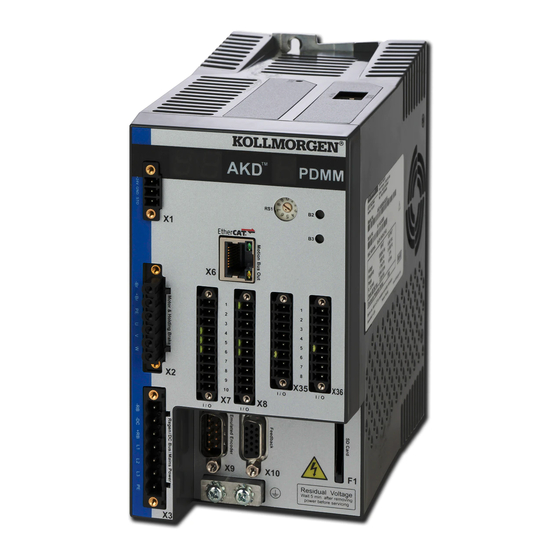
Page 157: Connection Diagrams
17.11 Mains Supply Connection (X3, X4) 17.12 I/O Connection 17.13 Analog Output (X8, X23) 17.14 Analog Input (X8, X24) 17.15 Command encoder signal connection 17.16 Pulse / Direction signal connection 17.17 Up / Down signal connection 17.18 Feedback Connector (X10) Kollmorgen™ | December 2012... - Page 158 AKD PDMM User Guide | 17 Connection Diagrams Kollmorgen™ | December 2012...
-
Page 159: Connection Diagram Akd Pdmm-X00306, Akd Pdmm-X00606
AKD PDMM User Guide | 17.1 Connection Diagram AKD PDMM-x00306, AKD PDMM-x00606 17.1 Connection Diagram AKD PDMM-x00306, AKD PDMM-x00606 17.2 Wiring Diagram 3 to 6A (230V) Kollmorgen™ | December 2012... - Page 160 AKD PDMM User Guide | 17.2 Wiring Diagram 3 to 6A (230V) The I/O option is available for AKD-T drives only. Kollmorgen™ | December 2012...
-
Page 161: Connection Diagram Akd Pdmm-X01206
AKD PDMM User Guide | 17.3 Connection Diagram AKD PDMM-x01206 17.3 Connection Diagram AKD PDMM-x01206 Kollmorgen™ | December 2012... -
Page 162: Wiring Diagram 12A (230V)
AKD PDMM User Guide | 17.4 Wiring Diagram 12A (230V) 17.4 Wiring Diagram 12A (230V) The I/O option is available for AKD-T drives only. Kollmorgen™ | December 2012... -
Page 163: Connection Diagram Akd Pdmm-X02406 And Akd Pdmm-Xzzz07
AKD PDMM User Guide | 17.5 Connection Diagram AKD PDMM-x02406 and AKD PDMM-xzzz07 17.5 Connection Diagram AKD PDMM-x02406 and AKD PDMM-xzzz07 17.6 Wiring Diagram 24A (230V) and 3 to 24 A (480V) Kollmorgen™ | December 2012... - Page 164 AKD PDMM User Guide | 17.6 Wiring Diagram 24A (230V) and 3 to 24 A (480V) The I/O option is available for AKD-T drives only. Kollmorgen™ | December 2012...
-
Page 165: Auxiliary Supply (X1)
The following diagram describes external 24 Vdc power supply, electrically isolated, for example, via an isolating transformer. The required current rating depends on the use of motor brake and option card ). Signal Description +24 Vdc Auxiliary voltage 24V Supply GND STO enable (Safe Torque Off) Kollmorgen™ | December 2012... -
Page 166: Motor Connection
Motor phase U Motor phase V Motor phase W Connector X2 AKD PDMM-xzzz07 Pin Signal Description Motor holding brake, negative Motor holding brake, positive Protective earth (motor housing) Motor phase U Motor phase V Motor phase W Kollmorgen™ | December 2012... -
Page 167: External Regen Resistor (X3)
For technical data on the brake circuit . Fusing (such as fusible cut-outs) to be provided by the user . AKD PDMM-x00106x00306 to AKD PDMM-x00606 (X3) Signal Description External Regen Resistor neg- ative External Regen Resistor pos- itive AKD PDMM-x01206 (X3) Signal Description +Rbint Internal RegenResistor positive External RegenResistor negative External RegenResistor positive Kollmorgen™ | December 2012... - Page 168 AKD PDMM User Guide | 17.9 External Regen Resistor (X3) AKD PDMM-x02406 & AKD PDMM-xzzz07 (X3) Signal Description External RegenResistor neg- ative External RegenResistor positive Kollmorgen™ | December 2012...
-
Page 169: Dc Bus Link (X3)
200 mm. Use shielded cables for longer lengths. AKD PDMM-x00106x00306 to AKD PDMM-x00606 (X3) Signal Description DC-Link Bus neg- ative +DC (+RB) DC-Link Bus positive AKD PDMM-x01206 (X3) Signal Description DC-Link Bus negative +DC (+RB) DC-Link Bus positive Kollmorgen™ | December 2012... -
Page 170: Mains Supply Connection (X3, X4)
Filtering for AKD PDMM-xzzz06 to be provided by the user. Fusing (such as fusible cut-outs) to be provided by the user . AKD PDMM-x00106x00306 to AKD PDMM- x00606 (X3) Signal Description Line 1 Line 2 Line 3 Protective Earth Kollmorgen™ | December 2012... - Page 171 AKD PDMM User Guide | 17.11.1 Three Phase connection (all AKD PDMM types) AKD PDMM-x01206 (X3) Signal Description Line 1 Line 2 Line 3 Protective Earth AKD PDMM-x02406 & AKD PDMM-xzzz07 (X4) Signal Description Line 1 Line 2 Line 3 Protective Earth Kollmorgen™ | December 2012...
-
Page 172: Single Phase Connection (Akd Pdmm-X00106X00306 To Akd Pdmm-X01206 Only)
Filtering to be provided by the user. Fusing (such as fusible cut-outs) to be provided by the user AKD PDMM-x00106x00306 to AKD PDMM-x00606 (X3) Signal Description Line 1 L2 (N) Neutral or Line 2 Protective Earth Kollmorgen™ | December 2012... -
Page 173: I/O Connection
Digital Output 2+ DIGITAL-OUT2+ Programmable => S. 1 Digital Output 1- DIGITAL-OUT1- Programmable Digital Output 1+ DIGITAL-OUT1+ Programmable Programmable, high Digital Input 2 DIGITAL-IN 2 speed => S. 1 Programmable, high Digital Input 1 DIGITAL-IN 1 speed Kollmorgen™ | December 2012... - Page 174 The DCOMx line should be connected to the 0V of the I/O supply when using sensors of type "Source" with digital inputs. The DCOMx line should be connected to the 24V of the I/O supply when using sensors of type "Sink" with digital inputs. Kollmorgen™ | December 2012...
-
Page 175: I/O Connectors X21, X22, X23 And X24 (Akd-T With I/O Option Card Only)
X22 pins 1, 2, 3 => p. 1 Digital Input 30 DIGITAL-IN 30 Programmable Digital Input 31 DIGITAL-IN 31 Programmable Digital Input 32 DIGITAL-IN 32 Programmable Common line for Digital Common X22/5_7 DCOM22.5_7 X22 pins 5, 6, 7 Kollmorgen™ | December 2012... - Page 176 Programmable Digital Output 28- DIGITAL-OUT 28- Programmable Digital Output 29+ DIGITAL-OUT 29+ Programmable Digital Output 29- DIGITAL-OUT 29- Programmable Relay Output 30 DIGITAL-OUT 30 Programmable, relay => S. 1 Relay Output 30 DIGITAL-OUT 30 Programmable, relay Kollmorgen™ | December 2012...
-
Page 177: I/O Connectors X35 And X36 (Akd Pdmm-M Only)
The DCOMx line should be connected to the 0V of the I/O supply when using sensors of type "Source" with digital inputs. The DCOMx line should be connected to the 24V of the I/O supply when using sensors of type "Sink" with digital inputs. Kollmorgen™ | December 2012... -
Page 178: Analog Output (X8, X23)
-3 dB Bandwidth: >8 kHz Maximum output current: 20 mA Capacitive load: any value but response speed limited by max Iout and by Rout Protected for short circuit to AGND Analog Output Wiring Diagram 1 Embedded Workbench Views Kollmorgen™ | December 2012... -
Page 179: Analog Input (X8, X24)
Defining the direction of rotation Standard setting: clockwise rotation of the motor shaft (looking at the shaft end) affected by positive volt- age between terminal (+ ) and terminal ( - ) Kollmorgen™ | December 2012... - Page 180 AKD PDMM User Guide | 17.14 Analog Input (X8, X24) To reverse the direction of rotation, swap the connections to terminals +/-, or change the DRV.DIR param- eter in the “Feedback 1” screen page. Kollmorgen™ | December 2012...
-
Page 181: Command Encoder Signal Connection
A 24 V A quad B encoder can be connected to the digital inputs 1 and 2 and used as a commander encoder, dual loop feedback, gearing or camming input. Don't use for primary motor feedback connection! Connection Diagram Kollmorgen™ | December 2012... -
Page 182: Encoder With Endat 2.2 Input 5 V (X9)
A single-turn or multi-turn encoder with EnDat 2.2 can be connected to this input and used as a com- mander encoder, dual loop feedback, gearing or camming input. Don't use for primary motor feedback con- nection! Connection Diagram Kollmorgen™ | December 2012... -
Page 183: Pulse / Direction Signal Connection
Connection industry standard 5V logic stepper-motor controllers with Pulse/Direction or Step/Direction outputs. Note that the X7 opto inputs can work with 5V up to 24V logic and so these inputs can be driven by 24V logic inputs as well. 1 Embedded Workbench Views Kollmorgen™ | December 2012... -
Page 184: Up / Down Signal Connection
The drive can be connected to a third-party controller which delivers 5 V up-down signals 17.17.2 Up / Down input 24 V (X7) The drive can be connected to a third-party controller which delivers 24 V up-down signals. Kollmorgen™ | December 2012... -
Page 185: Feedback Connector (X10)
BiSS C (digital) EnDAT 2.2 Smart Abs +Hall Hall U CLOCK+ CLOCK+ Hall V CLOCK- CLOCK- Hall W SENSE+ SENSE+ SENSE+ SENSE+ SENSE+ SENSE- SENSE- SENSE- SENSE- SENSE- COM+ DATA+ DATA+ Zero+ COM- DATA- DATA- Zero- Kollmorgen™ | December 2012... - Page 186 AKD PDMM User Guide | 17.18 Feedback Connector (X10) Tamagawa Incremental Encoder BiSS C (digital) EnDAT 2.2 Smart Abs +Hall Thermal control (PTC) Thermal control (PTC) +5 V +5 V +5 V +5 V +5 V Kollmorgen™ | December 2012...
-
Page 187: Block Diagrams
AKD PDMM User Guide | 18 Block Diagrams 18 Block Diagrams 18.1 Block Diagram for Current Loop 18.2 Block Diagram for Position/Velocity Loop Kollmorgen™ | December 2012... -
Page 188: Block Diagram For Current Loop
AKD PDMM User Guide | 18.1 Block Diagram for Current Loop 18.1 Block Diagram for Current Loop 18.2 Block Diagram for Position/Velocity Loop Kollmorgen™ | December 2012... -
Page 189: Akd Pdmm Firmware
7. Click the Upgrade Firmware button Give careful attention to any warning dialog that appears at this point. These warnings usually include important information about preventing damage to the drives. 8. Browse to select the new AKD firmware file Kollmorgen™ | December 2012... - Page 190 While the firmware is downloading to your drive, do not remove the 24V logic power. If you remove the 24V logic power during a firmware download, a severe drive crash can occur. If a crash occurs, the drive will restart in a special mode and prompt you to reload the firmware. Kollmorgen™ | December 2012...
-
Page 191: About The Parameter And Command Reference Guide
Object Dictionary for each ware version CAT COE and fieldbus, if the object dictionary contains more detailed infor- number required to CANopen . mation about the object. use the fieldbus. 1 Embedded Workbench Views Kollmorgen™ | December 2012... -
Page 192: Parameter And Command Naming Conventions
Current Current d-component Deceleration Direction Disable DIST Distance EMUE Emulated encoder Enable Error Fault Feedback Feedforward Gain Integrator Limit Loop Maximum Minimum Negative Nonvolatile Position, Proportional, Pos- itive Release Resistance STATE Status, State, Stat THRESH Threshold Kollmorgen™ | December 2012... -
Page 193: Summary Of Parameters And Commands
Reads the value of the analog input 2 signal. AIN2.ZERO Command Zeroes the analog input 2 signal. Analog Input/Output (AIO) AIO.ISCALE (pg 208) Sets the analog current scale factor. AIO.VSCALE (pg 209) Sets velocity scale factor. Kollmorgen™ | December 2012... - Page 194 BODE.VFTHRESH (pg Sets the current fault threshold for the BODE.MODE 5 stability 234) test. Capture (CAP) CAP0.EDGE, Selects the capture edge. CAP1.EDGE CAP0.EN, CAP1.EN Enables or disables the related capture engine. CAP0.EVENT, Controls the precondition logic. CAP1.EVENT Kollmorgen™ | December 2012...
- Page 195 Reads a specific digital input state. DIN32.STATE (pg 251) DIO9.INV to DIO11.INV Inverting the output voltage of the IO, when in the output direc- tion. DIO9.DIR to DIO11.DIR Changing direction of the IOs from the X9 connector. Kollmorgen™ | December 2012...
- Page 196 DRV.DISTO (pg 275) Sets the emergency timeout DRV.EMUEDIR (pg 276) Sets the direction of the emulated encoder output (EEO) signal. DRV.EMUEMODE (pg Sets the mode of the emulated encoder output (EEO) con- 277) nector. Kollmorgen™ | December 2012...
- Page 197 DRV.ONTIME (pg 293) Returns how long the drive has been running since last power DRV.OPMODE (PG 294) Sets the drive operation mode (current, velocity, or position). DRV.READFORMAT (PG Sets the value returned to either decimal or hexadecimal. 295) Kollmorgen™ | December 2012...
- Page 198 Sets initial feedback value as signed or unsigned. FB1.MECHPOS (PG 313) Reads the mechanical position. FB1.MEMVER Returns the memory feedback version. FB1.OFFSET (pg 314) Sets position feedback offset. FB1.ORIGIN (pg 315) Adds to the initial feedback position. Kollmorgen™ | December 2012...
- Page 199 Sets the counting direction for feedback channel 3. FB3.POFFSET (pg 329) Sets the offset for tertiary feedback. FB3.PUNIT (pg 329) Sets the unit for FB3.P. Fieldbus (FBUS) FBUS.PARAM1 TO Set fieldbus specific meanings. FBUS.PARAM10 (pg 332) Kollmorgen™ | December 2012...
- Page 200 Sets the proportional gain of the d-component current PI-reg- ulator as a percentage of IL.KP IL.KPLOOKUPINDEX (pg Sets the index into the Current Loop Gain Scheduling Table. 358) IL.KPLOOKUPVALUE (pg Sets the value of the current loop gain scheduling index. 359) Kollmorgen™ | December 2012...
- Page 201 381) MOTOR.IMID (pg 381) The direct-axis current set point used for induction machine closed-loop control. MOTOR.IMTR (pg 382) Rotor time constant. MOTOR.INERTIA (PG 383) Sets the motor inertia. MOTOR.IPEAK (PG 383) Sets the motor peak current. Kollmorgen™ | December 2012...
- Page 202 Limits the output of the position loop integrator by setting the output saturation. PL.KI (PG 407) Sets the integral gain of the position loop. PL.KP (PG 407) Sets the proportional gain of the position regulator PID loop. PL.MODP1 Sets modulo range parameter. Kollmorgen™ | December 2012...
- Page 203 Sets the regen resistor's power fault level for an external regen 426) resistor. SD card (SD) SD.LOAD (pg 428) Command Loads the drive state (BASIC program and NV parameters) from the SD card to the AKD PDMM (AKD PDMMs equipped with IO option card only). Kollmorgen™ | December 2012...
- Page 204 1 (velocity) and 2 (position) only. VL.ARZF1 TO VL.ARZF4 Sets the natural frequency of the zero (numerator) of anti-res- (pg 452) onance (AR)filter 1; active in opmodes 1 (velocity) and 2 (posi- tion) only. Kollmorgen™ | December 2012...
- Page 205 Select the type of commutation check to execute after Wake and Shake finds a new commutation angle. WS.CHECKT (pg 1) Sets the amount of time a communication error must be present before an error is thrown. Kollmorgen™ | December 2012...
- Page 206 Sets the ramp time for the ramp up current in Wake & Shake mode 1. WS.TSTANDSTILL (pg 1) Sets the calming time of the motor for Wake & Shake mode 1. WS.VTHRESH Defines the maximum allowed velocity for Wake & Shake Kollmorgen™ | December 2012...
-
Page 207: Aio Parameters
AKD PDMM User Guide | 21 AIO Parameters AIO Parameters This section describes the AIO parameters. 21.1 AIO.ISCALE 21.2 AIO.PSCALE 21.3 AIO.VSCALE Kollmorgen™ | December 2012... -
Page 208: Aio.iscale
1 to 9,223,372,036,854,775 counts/V 0 to 13,493,026.816 rad/V 0 to 773,094,113.280 deg/V 0 to 140,737,488,355.327 16-bit counts/V Range Linear: 1 to 9,223,372,036,854,775 counts/V 0 to 2147483.648 mm/V 0 to 2147483648.000 um/V 0 to 140737488355.327 16-bit counts/V Kollmorgen™ | December 2012... -
Page 209: Aio.vscale
0.060 to 60,000 rpm/V 0.001 to 1,000 rps/V 0.359 to 360,000 (deg/s)/V 0.006 to 6,283.186 (rad/s)/V Range Linear: 0.001 to 1.000 counts/s/V 0.001*MOTOR.PITCH (pg 387) to 1,000.000*MOTOR.PITCH (pg 387) (mm/s) 0.998*MOTOR.PITCH (pg 387) to 1,000,000.000*MOTOR.PITCH (pg 387) (um/s)/V Kollmorgen™ | December 2012... - Page 210 10 V of analog input or output. This value may be either higher or lower than the application velocity limit (VL.LIMITP or VL.LIMITN), but the actual analog I/O will be limited by VL.LIMITP or VL.LIMITN. Kollmorgen™ | December 2012...
-
Page 211: Aout Parameters
AKD PDMM User Guide | 22 AOUT Parameters AOUT Parameters This section describes the AOUT parameters. 22.1 AOUT.CUTOFF 22.2 AOUT.ISCALE 22.3 AOUT.MODE 22.4 AOUT.OFFSET 22.5 AOUT.PSCALE 22.6 AOUT.VALUE 22.7 AOUT.VALUEU 22.8 AOUT.VSCALE Kollmorgen™ | December 2012... -
Page 212: Aout.cutoff
This value may be either higher or lower than 100%, but the actual analog I/O will be limited by the application current limit (IL.LIMITN (pg 360) and IL.LIMITP (pg 361)). Related Topics Analog Output (pg 1) Kollmorgen™ | December 2012... -
Page 213: Aout.mode
Debug mode. In this mode the user can define a drive var- iable to monitor via the analog output (AOUT.VALUEU). Unfiltered Velocity (VL.FBUNFILTERED) Filtered Velocity - 10Hz Lowpass (VL.FBFILTER) Example You can use AOUT.MODE and AOUT.VALUEU to configure an output signal as follows: Kollmorgen™ | December 2012... -
Page 214: Aout.offset
1 to 9,223,372,036,854,775 counts/V 0 to 13,493,026.816 rad/V 0 to 773,094,113.280 deg/V 0 to 140,737,488,355.327 16-bit counts/V Range Linear: 1 to 9,223,372,036,854,775 counts/V 0 to 2,147,483.648 mm/V 0 to 2,147,483,648.000 µm/V 0 to 140,737,488,355.327 16-bit counts/V Kollmorgen™ | December 2012... -
Page 215: Aout.value
Reads the analog output Description value. Units Range –10 to +10 V Default Value Data Type Float See Also Start Version M_01-00-00-000 Fieldbus Information Fieldbus Index/Subindex Object Start Version EtherCAT COE and CAN- 3470h/2 M_01-00-00-000 open Description Kollmorgen™ | December 2012... -
Page 216: Aout.valueu
Analog Output (pg 1) 22.8 AOUT.VSCALE General Information Type NV Parameter Description Sets the velocity scale factor for analog output. Depends on UNIT.VROTARY or UNIT.ACCLINEAR Units Rotary: rpm/V, rps/V, (deg/s)/V, [(custom units)/s]/V, (rad/s)/V Linear: counts/s/V, (mm/s)/V, (μm/s)/V, [(custom units)/s]/V Kollmorgen™ | December 2012... - Page 217 This value may be either higher or lower than the application velocity limit (VL.LIMITP or VL.LIMITN), but the actual analog I/O will be limited by VL.LIMITP or VL.LI- MITN. Related Topics Analog Output (pg 1) Kollmorgen™ | December 2012...
-
Page 218: Aout2 Parameters
AKD PDMM User Guide | 23 AOUT2 Parameters AOUT2 Parameters This section describes the AOUT2 parameters. 23.1 AOUT2.CUTOFF 23.2 AOUT2.MODE 23.3 AOUT2.OFFSET 23.4 AOUT2.VALUE 23.5 AOUT.VALUEU Kollmorgen™ | December 2012... -
Page 219: Aout2.Cutoff
Mode 0: User variable. The analog output 2 signal is determined by the user (using AOUT.VALUEU (pg 220)). Example You can use AOUT.MODE and AOUT.VALUEU to configure an output signal as follows: -->AOUT.MODE 0 -->AOUT.VALUEU 5 -->AOUT.VALUEU 4.33 Related Topics 1 Analog Output Kollmorgen™ | December 2012... -
Page 220: Aout2.Offset
Start Version M_01-06-03-000 Description AOUT2.VALUE reads the analog output 2 value. Related Topics 1 Analog Output 23.5 AOUT.VALUEU General Information Type R/W Parameter Sets the analog output 2 Description value. Units Range –10 to +10 V Kollmorgen™ | December 2012... - Page 221 Value Data Type Float See Also Start Version M_01-06-03-000 Description AOUT2.VALUEU reads/writes the analog output 2 value when AOUT2.MODE (pg 219) = 0 (analog output signal is determined by the user). Related Topics 1 Analog Output Kollmorgen™ | December 2012...
-
Page 222: Bode Parameters
AKD PDMM User Guide | 24 BODE Parameters 24 BODE Parameters This section describes the BODE parameters. 24.1 BODE.EXCITEGAP 24.2 BODE.FREQ 24.3 BODE.IAMP 24.4 BODE.IFLIMIT 24.5 BODE.IFTHRESH 24.6 BODE.INJECTPOINT 24.7 BODE.MODE 24.8 BODE.MODETIMER 24.9 BODE.PRBDEPTH 24.10 BODE.VAMP 24.11 BODE.VFLIMIT 24.12 BODE.VFTHRESH Kollmorgen™ | December 2012... -
Page 223: Bode.excitegap
R/W Parameter Description Sets the frequency of the sine excitation source. Units Range 0 to 8,000 Hz Default 0 Hz Value Data Type Float BODE.MODE (pg 227) BODE.INJECTPOINT (pg 226), BODE.IAMP, See Also BODE.VAMP (pg 232) Kollmorgen™ | December 2012... -
Page 224: Bode.iamp
1, this parameter will determine the level of noise injected to commanded current value. Example Set the excitation current to 0.2 A: -->BODE.IAMP 0.2 Get the excitation current (already set to 0.2 A): -->BODE.IAMP 0.200 [A] Kollmorgen™ | December 2012... -
Page 225: Bode.iflimit
Set BODE.IFTHRESH to 6 Amps: -->BODE.IFTHRESH 6 Set BODE.IFLIMIT to 0.500 seconds: -->BODE.IFLIMIT 0.5 Set BODE.MODE to 5 to enable stability detection: BODE.MODE 5 Related Topics 1 Using the PST Using the Autotuner: Advanced F133 (pg 136) Kollmorgen™ | December 2012... -
Page 226: Bode.ifthresh
Units Range 0 to 2 Default Value Data Type Integer BODE.IAMP (pg 224), BODE.MODE (pg 227), BODE.VAMP (pg See Also 232) Start Version M_01-00-00-000 Description BODE.INJECTPOINT sets whether the excitation uses current or velocity excitation type. Kollmorgen™ | December 2012... -
Page 227: Bode.mode
If BODE.MODE is a nonzero value, and you reset BODE.MODE to another nonzero value, you will reset the watchdog timer. This mechanism is intended to turn off the exci- tation signal if you lose communication with the drive. Kollmorgen™ | December 2012... - Page 228 Uses random noise excitation. Noise is a random number gen- Noise erator that varies between +/- peak amplitude. Offset Sets a torque offset equal to BODE.IAMP Example Set BODE.MODE to PRB: -->BODE.MODE 1 Get BODE.MODE (already set to PRB): -->BODE.MODE 1 PRB excitation: Sine excitation: Kollmorgen™ | December 2012...
- Page 229 AKD PDMM User Guide | 24.7 BODE.MODE Noise excitation: Related Topics Using the PST Using the Autotuner: Advanced Kollmorgen™ | December 2012...
-
Page 230: Bode.modetimer
PRB excitation repeats every (2^BODE.PRBDEPTH)/BODE.- EXCITEGAP drive samples. This repetition can be used to reveal the effects of friction. Example Disable BODE.MODETIMER: -->BODE.MODETIMER // Set to 0 to disable the watchdog Kollmorgen™ | December 2012... -
Page 231: Bode.prbdepth
Using the Autotuner: Advanced Scope (pg 103) 1.2.1.5 Bode (set command source) 1 Settings (set command source) F126 (pg 136) Error: Invalid Bode plot mode for this function. (pg 154) and others) 24.9 BODE.PRBDEPTH General Information Type R/W Parameter Kollmorgen™ | December 2012... -
Page 232: Bode.vamp
Error: Invalid Bode plot mode for this function. (pg 154) and others) 24.10 BODE.VAMP General Information Type R/W Parameter Sets the amplitude of the excitation when in velocity Description mode. Rotary: rpm, rps, deg/s, rad/s Units Linear: counts/s, mm/s, µm/s Kollmorgen™ | December 2012... -
Page 233: Bode.vflimit
F126 (pg 136) Error: Invalid Bode plot mode for this function. (pg 154) and others) 24.11 BODE.VFLIMIT General Information Type R/W Parameter Sets the velocity fault duration limit (seconds) for the BODE.MODE 5 stability Description test Units Kollmorgen™ | December 2012... -
Page 234: Bode.vfthresh
Using the Autotuner: Advanced F133 (pg 136) 24.12 BODE.VFTHRESH General Information Type R/W Parameter Description Sets the current fault threshold for the BODE.MODE 5 stability test. Rotary: rpm, rps, deg/s, rad/s Units Linear: counts/s, mm/s, µm/s Kollmorgen™ | December 2012... - Page 235 Set BODE.VFTHRESH to 10 RPM: -->BODE.VFTHRESH 10 Set BODE.VFLIMIT to 0.500 seconds: -->BODE.VFLIMIT 0.5 Set BODE.MODE to 5 to enable stability detection: -->BODE.MODE 5 Related Topics 1 Using the PST Using the Autotuner: Advanced F133 (pg 136) Kollmorgen™ | December 2012...
-
Page 236: Cs Parameters
AKD PDMM User Guide | 25 CS Parameters 25 CS Parameters Controlled stop (CS) parameters set the values for the controlled stop process. 25.1 CS.DEC 25.2 CS.STATE 25.3 CS.TO 25.4 CS.VTHRESH Kollmorgen™ | December 2012... -
Page 237: Cs.dec
This parameter sets the deceleration value for the controlled stop process. Related Topics Controlled Stop (pg 65) 1 Digital Inputs and Outputs (Digital input mode 13) Fault and Warning Messages (pg 135) (this table indicates faults for which a controlled stop occurs) Kollmorgen™ | December 2012... -
Page 238: Cs.state
CS.DEC (pg 237), CS.VTHRESH (pg 240), CS.STATE, DRV.DIS, See Also DIN1.MODE TO DIN24.MODE (pg 247), DRV.DISMODE (pg 273), DRV.DI- SSOURCES (pg 274) Start Ver- M_01-00-00-000 sion Fieldbus Index/Subindex Object Start Version EtherCAT COE and CAN- 3440h/3 M_01-00-00-000 open Kollmorgen™ | December 2012... - Page 239 Set time value to 100 ms: -->CS.TO 100 Related Topics Controlled Stop (pg 65) 1 Digital Inputs and Outputs (Digital input mode 13) Fault and Warning Messages (pg 135) (this table indicates faults for which a controlled stop occurs) Kollmorgen™ | December 2012...
-
Page 240: Cs.vthresh
Set velocity threshold for controlled stop at 100 rpm: -->CS.VTHRESH 100 Related Topics Controlled Stop (pg 65) 1 Digital Inputs and Outputs (Digital input mode 13) Fault and Warning Messages (pg 135) (this table indicates faults for which a controlled stop occurs) Kollmorgen™ | December 2012... -
Page 241: Din Parameters
26.3 DIN.ROTARY 26.4 DIN.STATES 26.5 DIN1.FILTER TO DIN7.FILTER 26.6 DIN1.INV to DIN7.INV 26.7 DIN1.MODE TO DIN24.MODE 26.8 DIN1.PARAM TO DIN7.PARAM 26.9 DIN1.STATE TO DIN7.STATE 26.10 DIN9.STATE to DIN11.STATE 26.11 DIN21.FILTER to DIN32.FILTER 26.12 DIN21.STATE to DIN32.STATE Kollmorgen™ | December 2012... -
Page 242: Din.hcmd1 To Din.hcmd4
Units Range A string of up to 128 characters Default Empty Value Data Type String DIN1.MODE TO DIN24.MODE (pg 247), DIN1.PARAM TO DIN7.PARAM (pg See Also 248), DIN.HCMD1 TO DIN.HCMD4 (pg 242) Start Ver- M_01-02-08-000 sion Kollmorgen™ | December 2012... -
Page 243: Din.rotary
1 Digital Inputs and Outputs 26.3 DIN.ROTARY General Information Type R/O Parameter Reads the rotary knob Description value. Units Range 0 to 99 Default Value Data Type Integer See Also Start Version M_01-00-00-000 Description DIN.ROTARY reads the rotary knob value. Kollmorgen™ | December 2012... -
Page 244: Din.states
1 (DIN1) and the rightmost bit represents digital input 7 (DIN7). Related Topics 1 Digital Inputs and Outputs 26.5 DIN1.FILTER TO DIN7.FILTER General Information Type R/W Parameter Filter mode for digital inputs 1 to Description Units Kollmorgen™ | December 2012... -
Page 245: Din1.Inv To Din7.Inv
Boolean See Also Start Ver- M_01-00-00-000 sion Description Sets the indicated polarity of a digital input mode. Example DIN1.INV = 0 : Input is active high. DIN1.INV = 1 : Input is active low. Related Topics Kollmorgen™ | December 2012... - Page 246 AKD PDMM User Guide | 26.6 DIN1.INV to DIN7.INV Digital Inputs and Outputs Kollmorgen™ | December 2012...
-
Page 247: Din1.Mode To Din24.Mode
Fault reset 1 - Background Start motion task (use DINx.PARAM for this task) 2 - 1 KHz Start jog 6 - Background Reserved 7 - None Zero latch 8 - Background Command buffer 9 - Background Kollmorgen™ | December 2012... -
Page 248: Din1.Param To Din7.Param
This parameter sets a value that is used as an extra parameter for digital inputs nodes. Example The digital input mode "Start motion task" is used to start a motion task. This mode uses an extra parameter as the ID of the motion task to be started. Kollmorgen™ | December 2012... -
Page 249: Din1.State To Din7.State
1 Digital Inputs and Outputs 26.9 DIN1.STATE TO DIN7.STATE General Information Type R/O Parameter Reads a specific digital input Description state. Units Range 0 to 1 Default Value Data Type Integer See Also Start Version M_01-00-00-000 Description Kollmorgen™ | December 2012... -
Page 250: Din9.State To Din11.State
This parameter can be read at any time. The value is only guaranteed to correspond to the out- put on the X9 connector when DRV.EMUEMODE is set to 10 and the DIOX.DIR is 0. Related Topics DRV.EMUEMODE (pg 277) Kollmorgen™ | December 2012... -
Page 251: Din21.Filter To Din32.Filter
Digital Inputs and Outputs 26.12 DIN21.STATE to DIN32.STATE General Information Type R/O Parameter Reads a specific digital input Description state. Units Range 0 to 1 Default Value Data Type Integer See Also Start Version M_01-00-00-000 Description Kollmorgen™ | December 2012... - Page 252 AKD PDMM User Guide | 26.12 DIN21.STATE to DIN32.STATE DIN21.STATE to DIN32.STATE reads the state of one digital input according to the number identified in the command. Related Topics 1 Digital Inputs and Outputs Kollmorgen™ | December 2012...
-
Page 253: Dout Parameters
27.2 DOUT.RELAYMODE 27.3 DOUT.STATES 27.4 DOUT1.MODE to DOUT19.MODE 27.5 DOUT1.PARAM AND DOUT2.PARAM 27.6 DOUT1.STATE AND DOUT2.STATE 27.7 DOUT1.STATEU AND DOUT2.STATEU 27.8 DOUT9.STATE to DOUT11.STATE 27.9 DOUT9.STATEU to DOUT11.STATEU 27.10 DOUT21.STATE to DOUT32.STATE 27.11 DOUT21.STATEU to DOUT32.STATEU Kollmorgen™ | December 2012... -
Page 254: Dout.ctrl
If DOUT.RELAYMODE= 0 and faults do not exist, then the relay is closed. If DOUT.RELAYMODE = 1 and the drive is disabled, then the relay is open. If DOUT.RELAYMODE = 1 and the drive is enabled, then the relay is closed. Related Topics 1.4 Digital Outputs Kollmorgen™ | December 2012... -
Page 255: Dout.states
DOUTx.MODE sets the functionality of the digital outputs. The table below summarizes the digital output modes; for detailed descriptions of each mode, see Digital Inputs and Outputs. DOUTx.MODE Description User (default = 0) Mains ready Software limit switch reached Move complete Kollmorgen™ | December 2012... -
Page 256: Dout1.Param And Dout2.Param
Digital Output mode selected with the corresponding DOUTx.MODE. Below is a list of the possible range for each Digital Output Mode. If an output mode is not listed, then the default range of 0 is used. Kollmorgen™ | December 2012... -
Page 257: Dout1.State And Dout2.State
DOUT1.STATE and DOUT2.STATE read the state of one digital output according to the value stated in the command. Related Topics 1.4 Digital Outputs 27.7 DOUT1.STATEU AND DOUT2.STATEU General Information Type R/W Parameter Sets the state of the digital output Description node. Kollmorgen™ | December 2012... -
Page 258: Dout9.State To Dout11.State
This parameter can be read at any time. The value is only guaranteed to correspond to the out- put on the X9 connector when DRV.EMUEMODE is set to 10 and the DIOX.DIR is 0. Related Topics DOUT9.STATEU to DOUT11.STATEU (pg 259) DRV.EMUEMODE (pg 277) Kollmorgen™ | December 2012... -
Page 259: Dout9.Stateu To Dout11.Stateu
DRV.EMUEMODE 10 DIO10.DIR 1 DOUT10.STATEU 1 Then change the level of the signal: DOUT.STATEU 0 DIO10.INV Note: Inverting the signal will also alter the signal in input mode. Related Topics DOUT9.STATEU to DOUT11.STATEU DRV.EMUEMODE (pg 277) Kollmorgen™ | December 2012... -
Page 260: Dout21.State To Dout32.State
Start Version M_01-01-01-000 Description DOUTx.STATEU sets the state of the digital output node as follows: 0 = deactivated 1 = activated DOUTx.STATEU is used when DOUT1.MODE to DOUT19.MODE (pg 255) = 0 (user mode). Related Topics 1.4 Digital Outputs Kollmorgen™ | December 2012... -
Page 261: Drv Parameters
28.17 DRV.DISSOURCESMASK 28.18 DRV.DISTO 28.19 DRV.EMUECHECKSPEED 28.20 DRV.EMUEDIR 28.21 DRV.EMUEMODE 28.22 DRV.EMUEMTURN 28.23 DRV.EMUEPULSEWIDTH 28.24 DRV.EMUERES 28.25 DRV.EMUEZOFFSET 28.26 DRV.EN 28.27 DRV.ENDEFAULT 28.28 DRV.FAULTHIST 28.29 DRV.FAULT1 to DRV.FAULT10 28.30 DRV.FAULTS 28.31 DRV.HANDWHEELSRC 28.32 DRV.HELP 28.33 DRV.HELPALL Kollmorgen™ | December 2012... -
Page 262: Drv.acc
28.52 DRV.READFORMAT 28.53 DRV.RSTVAR 28.54 DRV.RUNTIME 28.55 DRV.SETUPREQBITS 28.56 DRV.SETUPREQLIST 28.57 DRV.STOP 28.58 DRV.TEMPERATURES 28.59 DRV.TIME 28.60 DRV.TYPE 28.61 DRV.VER 28.62 DRV.VERIMAGE 28.63 DRV.WARNING1 to DRV.WARNING10 28.64 DRV.WARNINGS 28.65 DRV.ZERO 28.1 DRV.ACC General Information Type NV Parameter Kollmorgen™ | December 2012... - Page 263 Data Type Float See Also DRV.DEC (pg 269), , Start Ver- M_01-00-00-000 sion Fieldbus Index/Subindex Object Start Version EtherCAT COE and CAN- M_01-00-00-000 open Description Describes the acceleration ramp for the velocity central loop. Related Topics Kollmorgen™ | December 2012...
-
Page 264: Drv.active
Causes the display to blink for 10 sec- Description onds. Units Range Default Value Data Type See Also Start Version M_01-00-00-000 Description DRV.BLINKDISPLAY causes the drive display located on the front of the drive to blink for 10 seconds. Kollmorgen™ | December 2012... -
Page 265: Drv.boottime
Data Type See Also DRV.FAULTHIST (pg 282) Start Version M_01-00-00-000 Description DRV.CLRFAULTHIST clears the fault history from the nonvolatile memory of the drive. This command erases all faults returned by DRV.FAULTHIST (pg 282). 1 Embedded Workbench Views Kollmorgen™ | December 2012... -
Page 266: Drv.clrfaults
DRV.CMDDELAY creates a delay in the execution of drive commands. In the period of time specified, no commands are executed. This feature is especially useful for command buffers.t Example If the script is: Kollmorgen™ | December 2012... -
Page 267: Drv.cmdsource
If you change DRV.CMDSOURCE from the terminal while the drive is ena- bled, the system may experience a step change in command. Example Kollmorgen™ | December 2012... -
Page 268: Drv.crashdump
(NV) memory within the drive. After the drive is restarted, you can use the DRV.CRASHDUMP command to retrieve this diagnostic information, which can be emailed to Kollmorgen for further support. If the drive crashes (display flashes an F and three bars), it saves the diagnostic information to a specific block of the drive NV memory. -
Page 269: Drv.dec
30.994*MOTOR.PITCH to 833,333,333.333*MOTOR.PITCH µm/s² 0.155 to 4,166,666.667 (custom units)/s² Rotary: 166.669 rps/s 10,000.000 rpm/s 60,000.000 deg/s² 833.333 (custom units)/s² Default 1,047.2 rad/s² Value Linear: 715,840,000.000 counts/s² 166.71*MOTOR.PITCH4MOTOR.PITCH (pg 387) mm/s² 166,714.191*MOTOR.PITCHMOTOR.PITCH (pg 387) µm/s² 833.571 (custom units)/s² Kollmorgen™ | December 2012... -
Page 270: Drv.difvar
This command also shows differences in parameters which hold a string, such as DRV.NAME. Example -->DRV.DIFVAR DRV.EMUEMODE 10 (0) DRV.NAME MyDrive(no-name) FB1.ENCRES 0(1024) IL.KP 50.009(24.811) PL.KP 99.998(49.999) VL.KP 0.108(0.000) Kollmorgen™ | December 2012... -
Page 271: Drv.dir
The drive status changes to "Axis not homed" as soon as the DRV.DIR parameter changes value (see DRV.MOTIONSTAT). You must verify the settings of the hardware limit switches. If necessary, switch the pos- itive and negative hardware limit switches by swapping the wires at the digital inputs. Kollmorgen™ | December 2012... -
Page 272: Drv.dis
Value Data Type DRV.EN (pg 281), DRV.DISSOURCES (pg 274), DRV.ACTIVE (pg 264), DRV.DISMODE (pg 273), See Also DRV.DISTO (pg 275) Start Ver- M_01-00-00-000 sion Fieldbus Index/Subindex Object Start Version EtherCAT COE and CAN- M_01-00-00-000 open Description Kollmorgen™ | December 2012... -
Page 273: Drv.dismode
Use a controlled stop to ramp down, and then use dynamic brake. The drive remains in the dynamic brake state after the motor has stopped. The drive is disabled in the sense that it does not close the control loop and cannot perform a motion, but PWM stays active. Kollmorgen™ | December 2012... -
Page 274: Drv.dissources
Initialization disable (the drive did not finish the initialization proc- ess) 5 Controlled stop disable from a digital input. 6 Field Bus requested disable (SynqNet and EtherNet/IP only) 7 AKD-C requested disable (AKD-N only) Related Topics Controlled Stop (pg 65) Kollmorgen™ | December 2012... -
Page 275: Drv.dissourcesmask
Related Topics DRV.DISSOURCES (pg 274) 28.18 DRV.DISTO General Information Type R/W Parameter Description Sets the emergency timeout Units Range 0 to 120,000 ms Default 1,000 ms Value Data Type DRV.DIS (pg 272), DRV.DISMODE (pg See Also 273) Kollmorgen™ | December 2012... -
Page 276: Drv.emuecheckspeed
(DRV.EMUEPULSEWIDTH). If the motor velocity exceeds this speed, fault F486 is raised. Related Topics 28.20 DRV.EMUEDIR General Information Type R/W Parameter Sets the direction of the emulated encoder output (EEO) sig- Description nal. Units Kollmorgen™ | December 2012... -
Page 277: Drv.emuemode
Z pulse. DRV.EMUEMTURN is used to define which turn of the position range the Z pulse is located. DRV.EMUEZOFFSET is used to define the position of the Z pulse within one revolution. This parameter sets the EEO connector to act as either an input or output as follows. Kollmorgen™ | December 2012... -
Page 278: Drv.emuemturn
DRV.EMUEMODE=2. Units revolutions Range 0 to 4,294,967,295 Default Value Data Type Integer See Also DRV.EMUEMODE (pg 277), DRV.EMUERES (pg 280) Start Ver- M_01-00-00-000 sion Fieldbus Index/Subindex Object Start Version EtherCAT COE and CAN- M_01-00-00-000 open Description Kollmorgen™ | December 2012... -
Page 279: Drv.emuepulsewidth
For each register increment the pulse width is raised by 0.52us Example 50 usecs pulse width emuOutPulseWidth = (50 usecs – 40 nsec)/520 nsec = 96 actual pulse = 96*520 nsec + 40 nsec = 49.88 usecs. Related Topics Kollmorgen™ | December 2012... -
Page 280: Drv.emueres
When emulated encoder output (EEO) multiturn is selected (DRV.EMUEMODE (pg 277)=1), this parameter is used by itself to define the position if the Z pulse within one revolution.When the primary feedback position (within a revolution) equals this value, an index pulse will output. Kollmorgen™ | December 2012... -
Page 281: Drv.en
DRV.EN is executed, then drive faults are automatically cleared during the software enable process. Related Topics 15.3 Clearing Faults 10.2 Enable/Disable 28.27 DRV.ENDEFAULT General Information Type R/W Parameter Sets the default state of the software ena- Description ble. Units Kollmorgen™ | December 2012... -
Page 282: Drv.faulthist
Issue a DRV.CLRFAULTHIST (pg 265) to clear this fault log. 28.29 DRV.FAULT1 to DRV.FAULT10 General Information Type Description Location of fault codes for any active fault conditions. Units Range Any supported fault code or 0. Kollmorgen™ | December 2012... -
Page 283: Drv.faults
To clear the faults, either issue a DRV.CLRFAULTS or issue a DRV.DIS followed by DRV.EN. If no active faults are in the system, then after executing DRV.CLRFAULTS the value read by DRV.FAULTS is "No faults active". Example -->DRV.FAULTS 502: Bus under voltage. --> Kollmorgen™ | December 2012... -
Page 284: Drv.handwheelsrc
(such as DRV.EN (pg 281)) or information commands (such as DRV.VER (pg 300)). Related Topics Terminal (pg 115) 28.33 DRV.HELPALL General Information Type R/O Parameter Retrieves the minimum, maximum, default, and actual values for all available Description parameters and commands. Kollmorgen™ | December 2012... -
Page 285: Drv.hwenable
The status of the power stage enable is determined by DRV.ACITVE. Related Topics DRV.DISSOURCES (pg 274) | DRV.ACTIVE 28.35 DRV.HWENDELAY General Information Type NV Parameter Delay time between inactive Hardware Enable input and Description drive disable. Kollmorgen™ | December 2012... -
Page 286: Drv.hwenmode
0 = The rising edge of the hardware enable will clear the drive faults. 1 = The rising edge of the hardware enable will not clear the drive faults. The high/low state of the hardware enable is always used to control the active enable state of the drive. Kollmorgen™ | December 2012... -
Page 287: Drv.icont
DRV.INFO returns general information about the drive. Example Advanced Kollmorgen™ Drive ------------------------------------------------------------------- Drive model : AKD-P00306-NACC-0000 Drive type : Position Indexer Continuous current : 3.000 Arms Peak current: 9.000 Arms Voltage : 120/240 Vac Option Board : Not applicable Connectivity : EtherCAT Kollmorgen™ | December 2012... -
Page 288: Drv.ipeak
Reads the peak rated current Description value. Units Arms Range Default Value Data Type Float See Also DRV.ICONT (pg 287) Start Version M_01-00-00-000 Description DRV.IPEAK returns the drive peak rated current in Arms. Related Topics 7.4 Foldback Kollmorgen™ | December 2012... -
Page 289: Drv.izero
Example Return a list of all available commands in the system: -->DRV.LIST Return all commands with the prefix DRV: -->DRV.LIST DRV 28.42 DRV.LOGICVOLTS General Information Type R/O Parameter Reads the logic volt- Description ages. Kollmorgen™ | December 2012... -
Page 290: Drv.memaddr
RAM, or asynchronous memory). The input value can be either decimal or hexadecimal with 0x prefix. Type extension can be one of the following: U8,S8,U16,S16,U32,S32,U64,S64. Examples Setting to an internal parameter: -->DRV.MEMADDR CCommandHandler.Debug1 Setting to an internal address: Kollmorgen™ | December 2012... -
Page 291: Drv.memdata
This name is one way to identify the drive in a multiple drive network (for instance, in a TCP/IP network on which multiple drives reside). From the terminal screen, DRV.NAME returns the name of the drive as ASCII characters. Kollmorgen™ | December 2012... -
Page 292: Drv.nvcheck
Range Default Value Data Type See Also Start Version M_01-00-00-000 Description DRV.NVLIST lists all the drive parameters that reside in NV memory. The list includes each parameter name, followed by its current value from the RAM. Kollmorgen™ | December 2012... -
Page 293: Drv.nvload
Executing DRV.RSTVAR does not modify the values of the NV, but instead sets the drive values in RAM to their defaults. 28.50 DRV.ONTIME General Information Type R/O Parameter Description Returns how long the drive has been running since last power up. Units Days:Hours:Minutes:Seconds Range Kollmorgen™ | December 2012... -
Page 294: Drv.opmode
If you change the operation mode from the terminal while the drive is enabled, the system may experience a step change in demand. Example Set the source of the command to a TCP/IP channel and the desired operation mode to veloc- ity: -->DRV.CMDSOURCE 0 -->DRV.OPMODE 1 Kollmorgen™ | December 2012... -
Page 295: Drv.readformat
28.53 DRV.RSTVAR General Information Type Command Sets default values in the drive without re-booting the drive and without reset- Description ting the NV memory. Units Range Default Value Data Type See Also Start Ver- M_01-00-00-000 sion Description Kollmorgen™ | December 2012... -
Page 296: Drv.runtime
This parameter returns the bitwise set status of parameters that needs to be set up before the drive can be enabled. Only when this parameter returns 0 can the drive be enabled. Parameter Bits IL.KP 0x00000001 MOTOR.IPEAK 0x00000002 MOTOR.ICONT 0x00000004 MOTOR.VMAX 0x00000008 MOTOR.POLES 0x00000010 MOTOR.PHASE 0x00000020 Kollmorgen™ | December 2012... -
Page 297: Drv.setupreqlist
Otherwise, the parameters must be set manually. Example -->DRV.SETUPREQLIST IL.KP 0 MOTOR.ICONT 0 MOTOR.IPEAK 0 MOTOR.POLES 0 --> 28.57 DRV.STOP General Information Type Command This command stops all drive Description motion. Units Range Default Value Data Type See Also Start Version M_01-00-00-000 Kollmorgen™ | December 2012... -
Page 298: Drv.temperatures
Power3 Temperature: Sensor does not exist. 28.59 DRV.TIME General Information Type Description A continuous time counter in the drive. Units Milliseconds Range 0 to 4294967295 (~ 49 days) Default Value Data Type Integer Start Ver- sion Description Kollmorgen™ | December 2012... -
Page 299: Drv.type
You cannot use EtherCAT and CANopen at the same time. Use FBUS.TYPE or DRV.INFO to identify the fieldbus currently in use. DRV.TYPE does not change if you use DRV.RSTVAR. Related Topics AKD PDMM Models (pg 19) Kollmorgen™ | December 2012... -
Page 300: Drv.ver
DRV.VERIMAGE reads the versions of the different images in the drive. This parameter returns the version data from each image .i00 file. Example Below is an example of the output for this parameter: Danaher Motion - Digital Servo Drive ------------------------------------ Kollmorgen™ | December 2012... -
Page 301: Drv.warning1 To Drv.warning10
Faults are not shown in the registers, only warnings. Related Topics DRV.FAULT1 to DRV.FAULT10 (pg 282) | 28.64 DRV.WARNINGS General Information Type R/O Parameter Reads the active warn- Description ings. Units Range Default Value Data Type Kollmorgen™ | December 2012... -
Page 302: Drv.zero
(by applying a current defined by DRV.IZERO (pg 289)). After the motor rests at this position, the commutation angle is cal- culated and set automatically. Kollmorgen™ | December 2012... -
Page 303: Eip Parameters
AKD PDMM User Guide | 29 EIP Parameters EIP Parameters This section describes the EIP parameters. 29.1 EIP.CONNECTED 29.2 EIP.POSUNIT 29.3 EIP.PROFUNIT Kollmorgen™ | December 2012... -
Page 304: Eip.connected
The default value is 2^16 = 65536, which provides 2^32 / 2^16 = 2^16 counts per revolution. A value of 1 would provide 2^32 / 1 = 2^32 counts per revolution. Related Topics EIP.PROFUNIT (pg 305) Kollmorgen™ | December 2012... -
Page 305: Eip.profunit
The default value is 2^16 = 65536, which provides 2^32 / 2^16 = 2^16 counts per second per rev- olution. A value of 1 would provide 2^32 / 1 = 2^32 counts per second per revolution. Related Topics EIP.POSUNIT (pg 304) Kollmorgen™ | December 2012... -
Page 306: Fault Parameters
AKD PDMM User Guide | 30 FAULT Parameters FAULT Parameters This section describes the FAULT parameters. 30.1 FAULTx.ACTION Kollmorgen™ | December 2012... -
Page 307: Faultx.action
Start Ver- M_01-04-16-000 sion Description This Parameter determines the action the drive should take when Fault 130, 131, 132, 134, 139, 451, or 702 occurs. Parameter Value Drive Action Disable Ampllifier Ignore (fault will not be reported) Kollmorgen™ | December 2012... -
Page 308: Fb1 Parameters
31.12 FB1.ORIGIN 31.13 FB1.P 31.14 FB1.PFIND 31.15 FB1.PFINDCMDU 31.16 FB1.POFFSET 31.17 FB1.POLES 31.18 FB1.PSCALE 31.19 FB1.PUNIT 31.20 FB1.RESKTR 31.21 FB1.RESREFPHASE 31.22 FB1.SELECT 31.23 FB1.TRACKINGCAL 31.24 FB1.USERBYTE0 to FB1.USERBYTE7 31.25 FB1.USERDWORD0 to FB1.USERWORD1 31.26 FB1.USERWORD1 to FB1.USERWORD3 Kollmorgen™ | December 2012... -
Page 309: Fb1.Bissbits
PPR by four. For example, for a 1024 PPR resolution motor, the number of encoder counts per revolution is 1024*4 = 4096. For this motor FB1.ENCRES must be set to 4096. Kollmorgen™ | December 2012... -
Page 310: Fb1.Hallstate
0 0 0 to 1 1 1 Default Value Data Type String See Also Start Version M_01-00-00-000 AKD BASIC Information Data Type Integer Description FB1.HALLSTATE reads the Hall switch values (encoder feedback only). Related Topics Feedback 1 (pg 45) Kollmorgen™ | December 2012... -
Page 311: Fb1.Hallstateu
Start Version M_01-03-07-000 Description FB1.HALLSTATEV reads the state of Hall switch V. Related Topics Feedback 1 (pg 45) 31.6 FB1.HALLSTATEW General Information Type R/O Parameter Reads the state of Hall switch Description Units Range 0 and 1 Kollmorgen™ | December 2012... -
Page 312: Fb1.Identified
Sine Encoder , with marker pulse and Hall Sine encoder , with marker pulse & No Halls EnDat 2.1 with Sine Cosine EnDat 2.2 BiSS with Sine Cosine HIPERFACE BiSS Mode C Renishaw Resolver 42 Tamagawa Related Topics Feedback 1 (pg 45) Kollmorgen™ | December 2012... -
Page 313: Fb1.Initsigned
Default Value Data Type Integer See Also Start Version M_01-00-00-000 Description FB1.MECHPOS reads the mechanical angle which is equal to the lower 32 bits in the 64-bit position feedback word. Related Topics Feedback 1 (pg 45) Kollmorgen™ | December 2012... -
Page 314: Fb1.Memver
-1192.878*MOTOR.PITCH (pg 387) to 1192.878*MOTOR.PITCH mm -1192877.952*MOTOR.PITCH to 1192877.952*MOTOR.PITCH µm -78176452.637 to 78176452.636 16-bit counts Default Value Data Type Float Start Version M_01-00-00-000 Fieldbus Index/Subindex Object Start Version EtherCAT COE and CAN- 3533h/0 M_01-00-00-000 open Description Kollmorgen™ | December 2012... -
Page 315: Fb1.Origin
The number of feedback bits is set according to the feedback type. For memory feedbacks it is the number of feedback bits; for none memory it is always single turn. The drive internal process for the feedback initialization is as follows: Kollmorgen™ | December 2012... -
Page 316: Fb1.P
Feedback 1 (pg 45) | FB1.PUNIT (pg 319) | FB1.PIN | FB1.POUT 31.14 FB1.PFIND General Information Type R/W Parameter A procedure that allows the user to find the commutation angle for Description encoder feedback, which has no halls. Units Range 0, 1 Default Value Kollmorgen™ | December 2012... -
Page 317: Fb1.Pfindcmdu
-5,123,372,000,000,005.000 to 5,123,372,000,000,005.000 counts Range -10,485,760.000 to 10,485,760.000 custom units Default Value Data Type See Also Start Version M_01-05-11-000 Description FB1.POFFSET is the value added to the primary feedback position (FB1.P (pg 316)). Kollmorgen™ | December 2012... -
Page 318: Fb1.Poles
FB1.PSCALE determines the counts per revolution of position values delivered by fieldbus. The default value is 20, which yields 2^20 counts/revolution. This scaling is used for CAN PDOs 6064 (Position Actual Value) and 60F4 (Following Error Actual Value). Kollmorgen™ | December 2012... -
Page 319: Fb1.Punit
Description Counts (32.32 format) (FB1.PIN/FB1.POUT) per revolution. Related Topics FB1.P (pg 316) 31.20 FB1.RESKTR General Information Type NV Parameter Sets the resolver nominal transformation Description ratio. Units Range 0.001 to 50.000 Default Value Data Type Float Kollmorgen™ | December 2012... -
Page 320: Fb1.Resrefphase
Sets user entered type or identified type (–1). Units Range –1, 10, 20, 30, 31, 32, 40, 41, 42 Default –1 Value Data Type Integer See Also FB1.IDENTIFIED Start Version M_01-00-00-000 Fieldbus Index/Subindex Object Start Version EtherCAT COE and CAN- M_01-00-00-000 open Kollmorgen™ | December 2012... - Page 321 The AKD PDMM is able to read this information, and automatically configure the drive for proper operation. Note that the devices SEK 90, SEK 160, and SEK 260 are label type 0xFF. Kollmorgen™ | December 2012...
-
Page 322: Fb1.Trackingcal
Value Data Type Integer See Also Start Version M_01-00-00-000 Description This parameter turns the tracking calibration algorithm on or off for sine-cosine or resolver. 0 = Tracking calibration is off. 1 = Tracking calibration is on. Kollmorgen™ | December 2012... -
Page 323: Fb1.Userbyte0 To Fb1.Userbyte7
DWORD0 DWORD1 For example, if BYTE1 is modified, WORD0 and DWORD0 are modified as well. Example -->FB1.USERDWORD1 65536 -->FB1.USERBYTE1 -->FB1.USERBYTE2 -->FB1.USERBYTE3 -->FB1.USERBYTE3 1 (write to the highest byte of FB1.USERDWORD0) -->FB1.USERDWORD0 16842752 -->FB1.USERWORD0 -->FB1.USERWORD1 Related Topics Kollmorgen™ | December 2012... -
Page 324: Fb1.Userdword0 To Fb1.Userword1
DWORD0 DWORD1 For example, if BYTE1 is modified, WORD0 and DWORD0 are modified as well. Example -->FB1.USERDWORD1 65536 -->FB1.USERBYTE1 -->FB1.USERBYTE2 -->FB1.USERBYTE3 -->FB1.USERBYTE3 1 (write to the highest byte of FB1.USERDWORD0) -->FB1.USERDWORD0 16842752 -->FB1.USERWORD0 -->FB1.USERWORD1 Related Topics Kollmorgen™ | December 2012... -
Page 325: Fb1.Userword1 To Fb1.Userword3
DWORD0 DWORD1 For example, if BYTE1 is modified, WORD0 and DWORD0 are modified as well. Example -->FB1.USERDWORD1 65536 -->FB1.USERBYTE1 -->FB1.USERBYTE2 -->FB1.USERBYTE3 -->FB1.USERBYTE3 1 (write to the highest byte of FB1.USERDWORD0) -->FB1.USERDWORD0 16842752 -->FB1.USERWORD0 -->FB1.USERWORD1 Related Topics Kollmorgen™ | December 2012... - Page 326 AKD PDMM User Guide | 31.26 FB1.USERWORD1 to FB1.USERWORD3 Feedback 1 (pg 45) | FB1.USERBYTE0 to FB1.USERBYTE7 (pg 323) | FB1.USERDWORD0 to FB1.USERWORD1 (pg 324) Kollmorgen™ | December 2012...
-
Page 327: Fb3 Parameters
AKD PDMM User Guide | 32 FB3 Parameters 32 FB3 Parameters This section describes the FB3 parameters. 32.1 FB3.MODE 32.2 FB3.P 32.3 FB3.PDIR 32.4 FB3.POFFSET 32.5 FB3.PUNIT Kollmorgen™ | December 2012... -
Page 328: Fb3.Mode
Endat 2.2 multiturn encoder. The output format is 32:32 the upper 32 bits represents the multiturns and the lower 32 bits for position of the feed- back. Related Topics DRV.EMUEMODE (pg 277) | FB3.PUNIT (pg 329) | FB3.PIN | FB3.POUT | FB3.PDIR (pg 329) Kollmorgen™ | December 2012... -
Page 329: Fb3.Pdir
Example If FB3.P is 10000 counts and FB3.POFFSET is set to –10000 counts, then the next read of FB3.P will return ~0 counts. 32.5 FB3.PUNIT General Information Type NV Parameter Description Sets the unit for FB3.P. Kollmorgen™ | December 2012... - Page 330 AKD PDMM User Guide | 32.5 FB3.PUNIT General Information Units Range 0, 3 Default Value Data Type See Also Start Version M_01-05-11-000 Description FB3.UNIT sets the position unit for FB3.P. Value Description Counts (32.32 format) (FB3.PIN/FB3.POUT) per revolution. Related Topics FB3.P (pg 328) Kollmorgen™ | December 2012...
-
Page 331: Fbus Parameters
AKD PDMM User Guide | 33 FBUS Parameters 33 FBUS Parameters This section describes the FBUS parameters. 33.1 FBUS.PARAM1 TO FBUS.PARAM10 33.2 FBUS.PLLSTATE 33.3 FBUS.PLLTHRESH 33.4 FBUS.PROTECTION 33.5 FBUS.REMOTE 33.6 FBUS.SAMPLEPERIOD 33.7 FBUS.STATE 33.8 FBUS.SYNCACT 33.9 FBUS.SYNCDIST 33.10 FBUS.SYNCWND 33.11 FBUS.TYPE Kollmorgen™ | December 2012... -
Page 332: Fbus.param1 To Fbus.param10
FBUS.PARAM01 sets the baud rate for the CANbus. Supported baud rates are 125, 250, 500 and 1000 kBaud. FBUS.PARAM02 switches the phase locked loop (PLL) for synchronized use: 0 = OFF, 1 = FBUS.PARAM03 sets the configured station alias for EtherCAT. Kollmorgen™ | December 2012... -
Page 333: Fbus.pllstate
Bit 5 = 1: EtherCAT: The setting of the rotary switches define the station alias address, if FBUS. PARAM03 is on 0 else FBUS.PARAM03 is used to store the station alias address. 33.2 FBUS.PLLSTATE General Information Type R/O Parameter Kollmorgen™ | December 2012... -
Page 334: Fbus.pllthresh
Description PLL. Units Range 0 to 10,000 Default Value Data Type Integer, U32 See Also Appendix B: Fieldbus Manuals Start Version M_01-00-00-000 Description This parameter sets number of successful synchronized cycles needed to lock the PLL. Kollmorgen™ | December 2012... -
Page 335: Fbus.protection
Value Description Motion and Tuning Commands Allowed - Commands that would interfere with motion are allowed. Gain and IO configuration changes are allowed. 1 Embedded Workbench Views Kollmorgen™ | December 2012... - Page 336 FBUS.PROTECTION 0 - Block Nothing 1 - Block Motion Commands 2 - Block All DRV.EN [Blocked] [Blocked] DRV.DIS FBUS.PROTECTION [Blocked] [Blocked] DRV.OPMODE [Blocked] [Blocked] DRV.CMDSOURCE DRV.STOP [Blocked] [Blocked] DRV.CLRFAULTS HOME.MODE HOME.ACC DRV.ACC DRV.DEC IL.LIMITN [Blocked] IL.LIMITP SM.MOVE MT.MOVE HOME.MOVE SM.MOVE PL.KP VL.KP [Blocked] VL.KI DINx.MODE DOUTx.MODE [Blocked] AINx.MODE AOUTx.MODE Kollmorgen™ | December 2012...
-
Page 337: Fbus.remote
10 seconds (for instance, -3 stands for mil- liseconds) and the units are the counts of these units. Kollmorgen recommends the following standard cycle rates, 250 us (4), 500 us (8), 1 ms (16), 2 ms (32), 4 ms (64). -
Page 338: Fbus.state
Default 0 ns Value Data Type Integer, U 32 See Also Appendix B: Fieldbus Manuals Start Version M_01-00-00-000 Description This parameter reads actual distance from the desired sync distance. 33.9 FBUS.SYNCDIST General Information Type NV Parameter Kollmorgen™ | December 2012... -
Page 339: Fbus.syncwnd
R/O Parameter Shows the active fieldbus Description type. Units Range 0 to 5 Default Value Data Type See Also Fieldbus Manuals Start Version M_01-00-00-000 Description FBUS.TYPE shows the active fieldbus type. 0 = Analog 1 = SynqNet Kollmorgen™ | December 2012... - Page 340 AKD PDMM User Guide | 33.11 FBUS.TYPE 2 = EtherCAT 3 = CANopen 4 = EthernetIP 5 = Profinet Kollmorgen™ | December 2012...
-
Page 341: Gui Parameters
GUI parameters are used within EWV for data reporting and data storage. 34.1 GUI.DISPLAY 34.2 GUI.PARAM01 34.3 GUI.PARAM02 34.4 GUI.PARAM03 34.5 GUI.PARAM04 34.6 GUI.PARAM05 34.7 GUI.PARAM06 34.8 GUI.PARAM07 34.9 GUI.PARAM08 34.10 GUI.PARAM09 34.11 GUI.PARAM10 1 Embedded Workbench Views Kollmorgen™ | December 2012... -
Page 342: Gui.display
The GUI uses this parameter to store data. Only the GUI can modify this data (not the user). 34.3 GUI.PARAM02 General Information Type NV Parameter Description Used by the GUI to store data. Units 2,147,483,648 to 2,147,483, Range Default Value Data Type Integer See Also Start Version M_01-00-00-000 Description Kollmorgen™ | December 2012... -
Page 343: Gui.param03
The GUI uses this parameter to store data. Only the GUI can modify this data (not the user). 34.6 GUI.PARAM05 General Information Type NV Parameter Description Used by the GUI to store data. Units 2,147,483,648 to 2,147,483, Range Default Value Data Type Integer See Also Start Version M_01-00-00-000 Kollmorgen™ | December 2012... -
Page 344: Gui.param06
The GUI uses this parameter to store data. Only the GUI can modify this data (not the user). 34.9 GUI.PARAM08 General Information Type NV Parameter Description Used by the GUI to store data. Units 2,147,483,648 to 2,147,483, Range Default Value Data Type Integer Kollmorgen™ | December 2012... -
Page 345: Gui.param09
Used by the GUI to store data. Units 2,147,483,648 to 2,147,483, Range Default Value Data Type Integer See Also Start Version M_01-00-00-000 Description The GUI uses this parameter to store data. Only the GUI can modify this data (not the user). Kollmorgen™ | December 2012... -
Page 346: Hwls Parameters
AKD PDMM User Guide | 35 HWLS Parameters 35 HWLS Parameters This section describes the HWLS parameters. 35.1 HWLS.NEGSTATE 35.2 HWLS.POSSTATE Kollmorgen™ | December 2012... -
Page 347: Hwls.negstate
0 to 1 Default Value Data Type Integer See Also HWLS.NEGSTATE (pg 347) Start Version M_01-00-00-000 Description HWLS.POSSTATE reads the status of the positive hardware limit switch as follows: 0 = Low 1 = High Related Topics Kollmorgen™ | December 2012... -
Page 348: Il Parameters
36.16 IL.KBUSFF 36.17 IL.KP 36.18 IL.KPDRATIO 36.19 IL.KPLOOKUPINDEX 36.20 IL.KPLOOKUPVALUE 36.21 IL.KPLOOKUPVALUES 36.22 IL.KVFF 36.23 IL.LIMITN 36.24 IL.LIMITP 36.25 IL.MFOLDD 36.26 IL.MFOLDR 36.27 IL.MFOLDT 36.28 IL.MI2T 36.29 IL.MI2TWTHRESH 36.30 IL.MIFOLD 36.31 IL.MIMODE 36.32 IL.OFFSET 36.33 IL.VCMD Kollmorgen™ | December 2012... -
Page 349: Il.busff
(such as a parameter setting or I t calculation). IL.CMD is limited also by motor peak current, IL.LIMITN (pg 360) and IL.LIMITP (pg 361). Related Topics 1 Current Loop 36.3 IL.CMDU General Information Type R/W Parameter Kollmorgen™ | December 2012... -
Page 350: Il.difold
(such as IL.LIMITP (pg 361)), it becomes the active current limit. IL.DIFOLD decreases when the actual current is higher than drive continuous current and increases (up to a certain level) when the actual current is lower than drive continuous current. Related Topics 1 Current Loop Kollmorgen™ | December 2012... -
Page 351: Il.fb
This parameter selects the feedback source that current loop use for commutation angle cal- culation. 0 = Primary feedback 1 = Secondary feedback For induction motor closed loop control the commutation angle is set as shown in the following figure. Kollmorgen™ | December 2012... -
Page 352: Il.ff
1 Current Loop 36.8 IL.FOLDFTHRESH General Information Type R/O Parameter Description Reads the foldback fault level. Units Arms Range 0 to 500 Arms Default Drive peak current Value (DRV.IPEAK) Data Type Float See Also Foldback Start Version M_01-00-00-000 Kollmorgen™ | December 2012... -
Page 353: Il.foldfthreshu
IL.FOLDFTHRESH is the minimum of DRV.IPEAK (pg 288), MOTOR.IPEAK (pg 383), and IL.FOLDFTHRESHU. Related Topics 1 Current Loop 36.10 IL.FOLDWTHRESH General Information Type NV Parameter Sets the foldback warning Description level. Units Arms Range 0 to 500 Arms Kollmorgen™ | December 2012... -
Page 354: Il.friction
Position command derivative sign is multiplied by this value to be injected to the current com- mand. IL.FRICTION is active in Position and Velocity modes (DRV.OPMODE = 1, 2), but not active in Torque mode (DRV.OPMODE = 0). Related Topics 1 Current Loop Kollmorgen™ | December 2012... -
Page 355: Il.ifold
Units Range ± Drive peak current (DRV.IPEAK) Default Value Data Type Float See Also Start Version M_01-00-00-000 Description This parameter displays the measured current in the u-winding of the motor. Related Topics 1 Current Loop Kollmorgen™ | December 2012... -
Page 356: Il.ivfb
This value sets the gain for the acceleration feedforward (a scaled second derivative of the posi- tion command is added to the current command value) . This parameter is valid only in the position mode (DRV.OPMODE = 2). Related Topics 1 Current Loop Kollmorgen™ | December 2012... -
Page 357: Il.kbusff
Start Version M_01-00-00-000 Fieldbus Index/Subindex Object Start Version EtherCAT COE and CAN- M_01-00-00-000 open Description IL.KP is used to modify the proportional gain of the PI-loop that controls the q-component of the current. Related Topics 1 Current Loop Kollmorgen™ | December 2012... -
Page 358: Il.kpdratio
0 A to 1.62 * DRV.IPEAK. To determine the level of current that corresponds to a table index, use the following equation: IL.CMD = (Table Index /157) * DRV.IPEAK Related Topics Current Loop Kollmorgen™ | December 2012... -
Page 359: Il.kplookupvalue
36.21 IL.KPLOOKUPVALUES General Information Type R/W Parameter Description Gets the Current Loop Gain Scheduling Table. Units Range Default Value Data Type Table IL.KPLOOKUPINDEX (pg 358), IL.KPLOOKUPVALUE (pg 359)IL.KP (pg See Also 357) Start Version M_01-04-00-000 Description Kollmorgen™ | December 2012... -
Page 360: Il.kvff
This parameter is only used in position mode (DRV.OPMODE (pg 294) = 2). Related Topics 1 Current Loop 36.23 IL.LIMITN General Information Type NV Parameter Sets the negative user (application-specific) current Description limit. Units Kollmorgen™ | December 2012... -
Page 361: Il.limitp
(IL.CMD (pg 349)). The current command is additionally limited by the motor peak current setting (MOTOR.IPEAK (pg 383)) and by the present value of the foldback I²t peak motor current protection. Related Topics 1 Current Loop Kollmorgen™ | December 2012... -
Page 362: Il.mfoldd
IL.MFOLDD time. The IL.MFOLDR value is automatically calculated from other foldback parameters. Related Topics 1 Current Loop 36.27 IL.MFOLDT General Information Type R/O Parameter Kollmorgen™ | December 2012... -
Page 363: Il.mi2T
IFOLD to MOTOR.ICONT case that the load reaches a value of 100%. The current limit IL.M- IFOLD will be restored to MOTOR.IPEAK in case that the load falls under 95%. Related Topics 1 Motor I2t algorithm 36.29 IL.MI2TWTHRESH General Information Type NV Parameter Motor I2t load warning thresh- Description old. Units Kollmorgen™ | December 2012... -
Page 364: Il.mifold
IL.MIFOLD decreases when the actual current is higher than motor continuous current and increases (up to a certain level) when the actual current is lower than the motor continuous cur- rent. Related Topics 1 Current Loop 36.31 IL.MIMODE General Information Type NV parameter Kollmorgen™ | December 2012... -
Page 365: Il.offset
Start Version M_01-00-00-000 Fieldbus Index/Subindex Object Start Version EtherCAT COE and CAN- M_01-00-00-000 open Description This value is added to the overall current loop feedforward value. Related Topics 1 Current Loop 36.33 IL.VCMD General Information Type R/O Parameter Kollmorgen™ | December 2012... -
Page 366: Il.vufb
Reads the measured voltage on the u-winding of the motor. Related Topics 1 Current Loop 36.35 IL.VVFB General Information Type R/O Parameter Reads the measured voltage on the v-winding of the Description motor. Units Range –1200*VBusScale to +1200*VBusScale Default Value Data Type Integer Kollmorgen™ | December 2012... - Page 367 The VBusScale parameter sets the drive model: MV/240 Vac: VBusScale = 1 HV/480 Vac: VBusScale = 2 VBusScale is used for multiple parameter ranges that are model dependent, such as IL.KP. Related Topics 1 Current Loop Kollmorgen™ | December 2012...
-
Page 368: Ip Parameters
AKD PDMM User Guide | 37 IP Parameters 37 IP Parameters This section describes the IP parameters. 37.1 IP.ADDRESS 37.2 IP.GATEWAY 37.3 IP.MODE 37.4 IP.RESET 37.5 IP.SUBNET Kollmorgen™ | December 2012... -
Page 369: Ip.address
The display will flash 0.0.0.0 and then attempt to discover an address by DHCP. Without removing logic power from the drive, use Workbench to connect to the drive, reconfigure the IP address settings as desired, and store the values to non-volatile memory. Related Topics IP.GATEWAY IP.RESET IP.SUBNET IP.MODE Kollmorgen™ | December 2012... -
Page 370: Ip.gateway
Workbench to connect to the drive, reconfigure the IP address settings as desired, and store the values to non-volatile memory. Related Topics IP.ADDRESS (pg 369) IP.RESET (pg 372) IP.SUBNET (pg 372) IP.MODE (pg 371) Kollmorgen™ | December 2012... -
Page 371: Ip.mode
Workbench to connect to the drive, reconfigure the IP address settings as desired, and store the values to non-volatile memory. Related Topics IP.ADDRESS (pg 369) IP.GATEWAY (pg 370) IP.RESET (pg 372) IP.SUBNET (pg 372) Kollmorgen™ | December 2012... -
Page 372: Ip.reset
Workbench to connect to the drive, reconfigure the IP address settings as desired, and store the values to non-volatile memory. Related Topics IP.ADDRESS (pg 369) IP.GATEWAY (pg 370) IP.SUBNET (pg 372) IP.MODE 37.5 IP.SUBNET General Information Type NV Parameter Kollmorgen™ | December 2012... - Page 373 The display will flash 0.0.0.0 and then attempt to discover an address by DHCP. Without removing logic power from the drive, use Workbench to connect to the drive, reconfigure the IP address settings as desired, and store the values to non-volatile memory. Related Topics IP.ADDRESS IP.GATEWAY IP.RESET 37.3 IP.MODE Kollmorgen™ | December 2012...
-
Page 374: Load-Parameter
AKD PDMM User Guide | 38 LOAD-Parameter 38 LOAD-Parameter This section describes the LOAD parameters. 38.1 LOAD.INERTIA Kollmorgen™ | December 2012... -
Page 375: Load.inertia
Units kg for linear motors 1 to 1,000,000 kgcm² or Range Default 0 kgcm² or kg Value Data Type Float See Also Start Version M_01-03-06-000 Description LOAD.INERTIA sets the load inertia. Related Topics Motor (pg 42) Kollmorgen™ | December 2012... -
Page 376: Motor Parameters
39.16 MOTOR.NAME 39.17 MOTOR.PHASE 39.18 MOTOR.PITCH 39.19 MOTOR.POLES 39.20 MOTOR.R 39.21 MOTOR.RTYPE 39.22 MOTOR.TBRAKEAPP 39.23 MOTOR.TBRAKERLS 39.24 MOTOR.TBRAKETO 39.25 MOTOR.TEMP 39.26 MOTOR.TEMPFAULT 39.27 MOTOR.TEMPWARN 39.28 MOTOR.TYPE 39.29 MOTOR.VMAX 39.30 MOTOR.VOLTMAX 39.31 MOTOR.VOLTMIN 39.32 MOTOR.VOLTRATED 39.33 MOTOR.VRATED Kollmorgen™ | December 2012... -
Page 377: Motor.autoset
Sets the presence or absence of a motor Description brake. Units Range 0 to 1 Default Value Data Type Boolean See Also Start Version M_01-00-00-000 AKD BASIC Information Data Type Integer Fieldbus Index/Subindex Object Start Version EtherCAT COE and CAN- M_01-00-00-000 open Description Kollmorgen™ | December 2012... -
Page 378: Motor.brakeimm
Motor (pg 42) | CS.VTHRESH (pg 240) | CS.TO (pg 238) | MOTOR.TBRAKETO (pg 390) | DRV.DISTO (pg 275) 39.4 MOTOR.BRAKERLS General Information Type Command Allows a user to release or apply the motor Description brake. Units Range 0 to 2 Kollmorgen™ | December 2012... -
Page 379: Motor.brakestate
A digital input mode is also used for the same purpose. The two mechanisms are independent. The CANopen-object 0x345A sub 1/2 can be used to control the brake state. CANopen manual on kollmorgen.com. (Functionality starts with firmware 1.7.4.0) Related Topics Motor (pg 42) 39.5 MOTOR.BRAKESTATE... -
Page 380: Motor.ctf0
Sets the motor continuous cur- Description rent. Units Range 0.1 to 500 A Default 1.0 A Value Data Type Float See Also Start Version M_01-00-00-000 AKD BASIC Information Type Fieldbus Index/Subindex Object Start Version EtherCAT COE and CAN- M_01-00-00-000 open Kollmorgen™ | December 2012... -
Page 381: Motor.iddatavalid
The direct-axis current set point used for induction machine closed-loop con- Description trol. Units Arms Range 0 to DRIVE.IPEAK Default Value Data Type Float Start Version M_01-08-00-000 Description The value of IL.IMID can be estimated using the motor name plate information. Kollmorgen™ | December 2012... -
Page 382: Motor.imtr
R from the following equivalent circuit of an induction machine. Alternatively, the rotor time constant can be estimated from the rated current, magnetizing cur- rent (MOTOR.IMID (pg 381)) and rated slip frequency as follows: Kollmorgen™ | December 2012... -
Page 383: Motor.inertia
EtherCAT COE and CAN- M_01-00-00-000 open Description This parameter sets the motor inertia. Related Topics 7.1 Motor 39.12 MOTOR.IPEAK General Information Type NV Parameter Description Sets the motor peak current. Units Range 0.200 to 1,000 A Kollmorgen™ | December 2012... -
Page 384: Motor.ke
Coil Voltage = MOTOR.KE * VL.FB Where: VL.FB is in units of krpm for rotary motors and in units of m/s for linear motors Related Topics Motor (pg 42) Kollmorgen™ | December 2012... -
Page 385: Motor.kt
1 to 2 Default 17.000 H Value Data Type Float See Also Start Version M_01-00-00-000 Fieldbus Index/Subindex Object Start Version EtherCAT COE and CAN- M_01-00-00-000 open Description This parameter is used to configure the motor line-to-line inductance. Kollmorgen™ | December 2012... -
Page 386: Motor.name
0 to 360° Default 0° Value Data Type Integer See Also Start Version M_01-00-00-000 Fieldbus Index/Subindex Object Start Version EtherCAT COE and CAN- M_01-00-00-000 open Description This parameter sets the motor phase. Related Topics 7.1 Motor Kollmorgen™ | December 2012... -
Page 387: Motor.pitch
(not pole pairs). The division value of motor poles (MOTOR.POLES) and feedback poles (FB1.POLES) must be an integer when setting drive to enable, otherwise a fault is issued. Related Topics 7.1 Motor Kollmorgen™ | December 2012... -
Page 388: Motor.r
Data Type Boolean See Also Start Version M_01-00-00-000 Description This parameter defines the type of thermal resistor used inside of the motor to measures motor temperature. 0 = PTC 1 = NTC Related Topics Motor (pg 42) Kollmorgen™ | December 2012... -
Page 389: Motor.tbrakeapp
EtherCAT COE and CAN- M_01-00-00-000 open Description This parameter is used to configure the mechanical delay when releasing the motor brake. MOTOR.TBRAKERLS is a time delay that is applied when a brake exists and the drive is Kollmorgen™ | December 2012... -
Page 390: Motor.tbraketo
Reads the motor temperature represented as the resistance of the motor Description PTC. Units Ω Range 0 to 2 Ω Default Value Data Type Integer See Also Start Version M_01-00-00-000 Fieldbus Index/Subindex Object Start Version EtherCAT COE and CAN- M_01-00-00-000 open Kollmorgen™ | December 2012... -
Page 391: Motor.tempfault
Units Ω Range 0 to 2,000,000,000 Ω Default 0 Ω = switched off Value Data Type Integer See Also MOTOR.TEMP (pg 390) Start Version M_01-00-00-000 Fieldbus Index/Subindex Object Start Version EtherCAT COE and CAN- M_01-00-00-000 open Kollmorgen™ | December 2012... -
Page 392: Motor.type
Open Loop Closed Loop MOTOR.NAME (pg 386) MOTOR.TYPE MOTOR.AUTOSET (pg 377) MOTOR.IPEAK (pg 383) MOTOR.ICONT (pg 380) Yes MOTOR.INERTIA (pg 383) MOTOR.KT (pg 385) MOTOR.LQLL (pg 385) MOTOR.POLES (pg 387) Yes MOTOR.VMAX (pg 393) MOTOR.R (pg 388) Kollmorgen™ | December 2012... -
Page 393: Motor.vmax
EtherCAT COE and CAN- M_01-00-00-000 open Description This parameter is used to configure the maximum speed of the motor. Related Topics 7.1 Motor 39.30 MOTOR.VOLTMAX General Information Type NV Parameter Sets the motor maximum volt- Description age. Kollmorgen™ | December 2012... -
Page 394: Motor.voltmin
(%) of the motor’s rated voltage. MOTOR.VOLTMIN is used to calculate the constant volts per Hertz characteristics of the drive and motor and should be set to a value that generates a current of about 40% of the rated current at standstill. Related Topics 7.1 Motor Kollmorgen™ | December 2012... -
Page 395: Motor.voltrated
0.000 to 90,000.000 deg/s 0.000 to 1,250.000 custom units/s Range 0.000 to 1,570.796 rad/s Linear: 0.000 to 1,073,741,824,000.000 counts/s 0.000 to 8,000.000 mm/s 0.000 to 8,000,000.000 µm/s 0.000 to 1,250.000 custom units/s Default 0 rpm Value Kollmorgen™ | December 2012... - Page 396 This parameter configures the drive for the rated velocity of the induction motor as indicated on the nameplate. MOTOR.VRATED is used to calculate the constant volts per Hertz characteristics of the drive and motor. Related Topics Motor (pg 42) Kollmorgen™ | December 2012...
-
Page 397: Pl Parameters
AKD PDMM User Guide | 40 PL Parameters PL Parameters This section describes the PL parameters. 40.1 PL.CMD 40.2 PL.ERR 40.3 PL.ERRFTHRESH 40.4 PL.ERRMODE 40.5 PL.ERRWTHRESH 40.6 PL.FB 40.7 PL.FBSOURCE 40.8 PL.INTINMAX 40.9 PL.INTOUTMAX 40.10 PL.KI 40.11 PL.KP Kollmorgen™ | December 2012... -
Page 398: Pl.cmd
(custom units) Range Default Value Data Type Float See Also PL.FB (pg 403) Start Version M_01-00-00-000 AKD BASIC Information Data Type Integer Fieldbus Index/Subindex Object Start Version EtherCAT COE and CAN- M_01-00-00-000 open Description Kollmorgen™ | December 2012... -
Page 399: Pl.errfthresh
0.000 to 5,964,389.888 (custom units) 0.000 to 78,176,452,636.718 16-bit counts Range Linear: 0.000 to 5,123,372,000,000,005.000 counts 0.000 to 1,192,877.952*MOTOR.PITCH (pg 387) mm 0.000 to 1,192,878,014.464*MOTOR.PITCH (pg 387) µm 0.000 to 5,964,389.888 (custom units) 0.000 to 78,176,452,636.718 16-bit counts Kollmorgen™ | December 2012... -
Page 400: Pl.errmode
PL.ERR (pg 398) | PL.ERRMODE (pg 400) | PL.ERRWTHRESH (pg 401) 1 Position Loop 40.4 PL.ERRMODE General Information Type NV Parameter Description Sets the type of following error warning and fault usage. 0- Standard following error Units 1-Enhanced following error Range 0 to 1 Kollmorgen™ | December 2012... -
Page 401: Pl.errwthresh
In this case the warning is generated, as well as the fault. Related Topics PL.ERR (pg 398) | PL.ERRFTHRESH (pg 399) | PL.ERRWTHRESH (pg 401) 1 Position Loop 40.5 PL.ERRWTHRESH General Information Type NV Parameter Description Sets the position error warning level. Kollmorgen™ | December 2012... - Page 402 Set position rotary units to 2 degrees. If you set PL.ERRWTHRESH to 100 and the position error is larger than 100 degrees, then the drive will generate a warning. UNIT.PROTARY 2 PL.ERRWTHRESH 100 Related Topics PL.ERR (pg 398) | PL.ERRFTHRESH (pg 399) | PL.ERRMODE (pg 400) 1 Position Loop Kollmorgen™ | December 2012...
-
Page 403: Pl.fb
AKD BASIC Example Print PL.FB, MOVE.POSCOMMAND MOVE.POSCOMMAND Print PL.FB, MOVE.POSCOMMAND Related Topics PL.ERR (pg 398) | PL.ERRFTHRESH (pg 399) | PL.ERRMODE (pg 400) | PL.ERRWTHRESH (pg 401) 1 Position Loop 40.7 PL.FBSOURCE General Information Type NV Parameter Kollmorgen™ | December 2012... -
Page 404: Pl.intinmax
NV Parameter Limits the input of the position loop integrator by setting the input sat- Description uration. Depends on or Units Rotary: counts, rad, deg, (custom units), 16-bit counts Linear: counts, mm, µm, (custom units), 16-bit counts Kollmorgen™ | December 2012... - Page 405 Far from the target position, however,the integrator is not dominant in the loop dynamics. Related Topics PL.ERR (pg 398) | PL.ERRFTHRESH (pg 399) | PL.ERRMODE (pg 400) | PL.ERRWTHRESH (pg 401) 1 Position Loop Kollmorgen™ | December 2012...
-
Page 406: Pl.intoutmax
When used in concert with PL.INTINMAX, this variable allows you to make the position loop integrator effective near the target position. Far from the target position, however, the integrator is not dominant in the loop dynamics. Related Topics Kollmorgen™ | December 2012... -
Page 407: Pl.ki
100 rps/rev Value Data Type Float See Also PL.KI (pg 407), Start Version M_01-00-00-000 Fieldbus Index/Subindex Object Start Version EtherCAT COE and CAN- M_01-00-00-000 open Description PL.KP sets the proportional gain of the position regulator PID loop. Kollmorgen™ | December 2012... - Page 408 AKD PDMM User Guide | 40.11 PL.KP Related Topics PL.ERR (pg 398) | PL.ERRFTHRESH (pg 399) | PL.ERRMODE (pg 400) | PL.ERRWTHRESH (pg 401) 1 Position Loop Kollmorgen™ | December 2012...
-
Page 409: Rec Parameters
41.3 REC.DONE 41.4 REC.GAP 41.5 REC.NUMPOINTS 41.6 REC.OFF 41.7 REC.RECPRMLIST 41.8 REC.RETRIEVE 41.9 REC.RETRIEVEDATA 41.10 REC.RETRIEVEFRMT 41.11 REC.RETRIEVEHDR 41.12 REC.RETRIEVESIZE 41.13 REC.STOPTYPE 41.14 REC.TRIG 41.15 REC.TRIGPARAM 41.16 REC.TRIGPOS 41.17 REC.TRIGPRMLIST 41.18 REC.TRIGSLOPE 41.19 REC.TRIGTYPE 41.20 REC.TRIGVAL Kollmorgen™ | December 2012... -
Page 410: Rec.active
Set one of the recordable commands. The list of recordable commands can be obtain by executing REC.RECPRMLIST (pg 412). Set an internal value or variable of the drive (same as for DRV.MEMADDR (pg 290) input). Related Topics Kollmorgen™ | December 2012... -
Page 411: Rec.done
REC.GAP specifies the gap between consecutive samples. The recording base rate is 16 kHz, thus a gap of 1 means that a sample is recorded every 62.5 µs. Related Topics Scope (pg 103) 41.5 REC.NUMPOINTS General Information Type R/W Parameter Kollmorgen™ | December 2012... -
Page 412: Rec.off
REC.OFF turns the recorder off. In order to set the recorder again, the recorder must first be armed and then a trigger set. Related Topics Scope (pg 103) REC.READY 41.7 REC.RECPRMLIST General Information Type R/O Parameter Reads the list of recordable param- Description eters. Units Range Kollmorgen™ | December 2012... -
Page 413: Rec.retrieve
The following format is the retrieve reply format (for N samples, G sample gap, and M param- eters, where M<=6): Recording <N>,<G> <parameter name 1> … <parameter name M> Value11 … Value1M Value N1 … ValueNM Related Topics Scope (pg 103) Kollmorgen™ | December 2012... -
Page 414: Rec.retrievedata
A new REC.TRIG (pg 417) command automatically sets the index to 0. Example The following example retrieves data from index 100 in the size of 10 (hence places 100 to 109 in the buffer) REC.NUMPOINTS 1000 REC.RETRIVESIZE 10 REC.TRIG REC.RETRIEVEDATA 100 Related Topics 1 Embedded Workbench Views Kollmorgen™ | December 2012... -
Page 415: Rec.retrievefrmt
The following recorder data is in internal format: 10,1 IL.FB,VL.CMD,VL.FB F3-0x56,F30x0,F30xA65 F30x0,F30x0,F30xE15 F30x1D,F30x0,F3-0x1E6 Related Topics Scope (pg 103) 41.11 REC.RETRIEVEHDR General Information Type R/O Parameter Retrieves the recorded header without the Description data. Units 1 Embedded Workbench Views Kollmorgen™ | December 2012... -
Page 416: Rec.retrievesize
Use REC.RETRIEVE (pg 413) for the complete recording information view. Related Topics Scope (pg 103) 41.13 REC.STOPTYPE General Information Type R/W Parameter Description Sets the recorder stop type. 1 Embedded Workbench Views 2 Embedded Workbench Views Kollmorgen™ | December 2012... -
Page 417: Rec.trig
No REC parameters can be set after a call to REC.TRIG until the recorder has finished or until REC.OFF is executed. Related Topics Scope (pg 103) 41.15 REC.TRIGPARAM General Information Type R/W Parameter Kollmorgen™ | December 2012... -
Page 418: Rec.trigpos
0 ms in the data time and 100-x% (the rest of the data) is at or greater than 0 ms. In the figure below, the trigger position is set to 25% (REC.TRIGPOS 25). Kollmorgen™ | December 2012... -
Page 419: Rec.trigprmlist
(input to REC.TRIGPARAM). Note that an internal address or a registered variable can be used as input to REC.TRI- GPARAM in addition to the list that this parameter returns. Related Topics Scope (pg 103) 1 Embedded Workbench Views Kollmorgen™ | December 2012... -
Page 420: Rec.trigslope
REC.TRIGTYPE sets the type of trigger. Input values are as follows: Value Description Recording starts immediately Recording starts on the next command executed through the TCP/IP. The trigger loca- tion in the buffer is set according to REC.TRIGPOS. Kollmorgen™ | December 2012... -
Page 421: Rec.trigval
M_01-00-00-000 sion Description REC.TRIGVAL is the value that must be met by REC.TRIGPARAM for the trigger to occur. The units of this parameter are set according to the units of REC.TRIGPARAM. Related Topics Scope (pg 103) Kollmorgen™ | December 2012... -
Page 422: Regen Parameters
AKD PDMM User Guide | 42 REGEN Parameters REGEN Parameters This section describes the REGEN parameters. 42.1 REGEN.POWER 42.2 REGEN.POWERFILTERED 42.3 REGEN.REXT 42.4 REGEN.TEXT 42.5 REGEN.TYPE 42.6 REGEN.WATTEXT Kollmorgen™ | December 2012... -
Page 423: Regen.power
If REGEN.POWERFILTERED exceeds the value of REGEN.WATTEXT, Fault 521 (Regen overpower) will be generated. This keyword may be recorded in the scope screen for analysis. Example REGEN.TEXT = 10 (seconds) Lowpass Filter Frequence = 1/10 seconds = 0.1 Hz REGEN.POWERFILTERED = REGEN.POWER * 0.1Hz lowpass Kollmorgen™ | December 2012... -
Page 424: Regen.rext
REGEN.TEXT is a thermal time constant used to protect an external regeneration (regen) resistor from overheating and failing. Its value is the time-to-fault when input power steps from 0 to 150% of REGEN.WATTEXT (pg 426). The drive's regen resistor protection algorithm Kollmorgen™ | December 2012... -
Page 425: Regen.type
You can specify a user-defined external regen resistor, select an internal regen resistor, or choose from a list of predefined regen resistors. The values for REGEN.TYPE are shown below: Type Description External user-defined regen –1 resistor Internal regen resistor Kollmorgen™ | December 2012... -
Page 426: Regen.wattext
Sets the regen resistor's power fault level for an external regen resistor (when REGEN.TYPE = -1). Above this fault level, the regen resistor's PWM wil be 0 and a fault will be issued. Related Topics 6.2 Regeneration Kollmorgen™ | December 2012... -
Page 427: Sd Commands
AKD PDMM User Guide | 43 SD Commands 43 SD Commands This section describes commands for SD Card functions. 43.1 SD.LOAD 43.2 SD.SAVE 43.3 SD.STATUS Kollmorgen™ | December 2012... -
Page 428: Sd.load
General Information Type Command Saves the drive state (BASIC program and NV parameters) to the SD card Description (AKD PDMMs equipped with IO option card only). Units Range Default Value Data Type Start Ver- M_01-06-03-000 sion Description Kollmorgen™ | December 2012... -
Page 429: Sd.status
Read Only – an SD card is inserted into the drive and the write protection tab on the card prohibits writes. Not Inserted – an SD card is not inserted into the drive. Related Topics SD.LOAD (pg 428) | SD.SAVE (pg 428) Kollmorgen™ | December 2012... -
Page 430: Sm Parameters
AKD PDMM User Guide | 44 SM Parameters 44 SM Parameters This section describes the SM parameters. 44.1 SM.I1 44.2 SM.I2 44.3 SM.MODE 44.4 SM.MOVE 44.5 SM.T1 44.6 SM.T2 44.7 SM.V1 44.8 SM.V2 Kollmorgen™ | December 2012... -
Page 431: Sm.i1
SM.I2 defines the current that is used in service motion mode 1 (see SM.MODE (pg 431)). Related Topics Service Motion (pg 73) 44.3 SM.MODE General Information Type NV Parameter Description Sets the service motion mode. Units Kollmorgen™ | December 2012... - Page 432 (SM.T2). This sequence is repeated as long as a DRV.STOP command occurs. The drive will gen- erate an acceleration and deceleration ramps according to the DRV.ACC and DRV.DEC setting in this mode of oper- ation. Kollmorgen™ | December 2012...
- Page 433 The deceleration process from SM.V1 or SM.V2 to 0 is not included in SM.T1 and SM.T2, respectively. SM.T1 and SM.T2 start as soon as the command value has reached the velocity Related Topics Service Motion (pg 73) Kollmorgen™ | December 2012...
-
Page 434: Sm.move
SM.MODE). For an alternating service motion mode, SM.T1 may not be set to 0. Related Topics Service Motion (pg 73) 44.6 SM.T2 General Information Type NV Parameter Description Sets the service motion time 2. Units Range 0 to 65,535 ms Kollmorgen™ | December 2012... -
Page 435: Sm.v1
-250,000.000*MOTOR.PITCH (pg 387) to 250,000.000*MOTOR.PITCH (pg 387) µm/s -1,250.000 to 1,250.000 custom units/s Rotary: 60.000 rpm 1.000 rps 359.999 deg/s 5.000 custom units/s Default 6.283 rad/s Value Linear: 0.001 Counts/s 1.000*MOTOR.PITCH (pg 387) mm/s 999.998*MOTOR.PITCH (pg 387) µm/sec 5.000 custom units/s Kollmorgen™ | December 2012... -
Page 436: Sm.v2
-5.000 custom units/s Default -6.283 rad/s Value Linear: -0.001 counts/s -1.000*MOTOR.PITCH (pg 387) mm/s -999.998*MOTOR.PITCH (pg 387) µm/sec -5.000 custom units/s Data Type Float See Also SM.I1, SM.I2, SM.MODE, SM.MOVE, SM.T1, SM.T2, SM.V1 Start Ver- M_01-00-00-000 sion Kollmorgen™ | December 2012... - Page 437 AKD PDMM User Guide | 44.8 SM.V2 Description SM.V2 defines the velocity that is used in service motion mode 1 (see SM.MODE) in the closed velocity and position mode of operation. Related Topics 11.1 Service Motion Kollmorgen™ | December 2012...
-
Page 438: Sto Parameters
AKD PDMM User Guide | 45 STO Parameters 45 STO Parameters This section describes the STO parameters. 45.1 STO.STATE Kollmorgen™ | December 2012... -
Page 439: Sto.state
Start Version M_01-00-00-000 Description STO.STATE returns the status of the safe torque off. 1 - Safe torque on (no safe torque off fault). 0 - Safe torque off (safe torque off fault ). Related Topics 10.1 Limits Kollmorgen™ | December 2012... -
Page 440: Swls Parameters
AKD PDMM User Guide | 46 SWLS Parameters 46 SWLS Parameters This section describes the SWLS parameters. 46.1 SWLS.EN 46.2 SWLS.LIMIT0 46.3 SWLS.LIMIT1 46.4 SWLS.STATE Kollmorgen™ | December 2012... -
Page 441: Swls.en
Whichever switch is set largest is the positive limit switch; the other switch becomes the negative limit switch. These switches can be used in addition to hardware Kollmorgen™ | December 2012... -
Page 442: Swls.limit1
HOME Parameters and DRV.MOTIONSTAT. Related Topics 10.1 Limits 46.4 SWLS.STATE General Information Type R/O Parameter Reads the actual status of software limit Description switches. Units Range 0 to 3 Default Value Data Type See Also Start Version M_01-00-00-000 Description Kollmorgen™ | December 2012... - Page 443 Bit 0 = 1: SWLS.LIMIT0 is active. Bit 1 = 0: SWLS.LIMIT1 (pg 442) is not active. Bit 1 = 1: SWLS.LIMIT1 is active. Bits 2 to 7 are currently not in use. Related Topics 10.1 Limits Kollmorgen™ | December 2012...
-
Page 444: Vbus Parameters
AKD PDMM User Guide | 47 VBUS Parameters 47 VBUS Parameters This section describes the VBUS parameters. 47.1 VBUS.HALFVOLT 47.2 VBUS.OVFTHRESH 47.3 VBUS.OVWTHRESH 47.4 VBUS.RMSLIMIT 47.5 VBUS.UVFTHRESH 47.6 VBUS.UVMODE 47.7 VBUS.UVWTHRESH 47.8 VBUS.VALUE Kollmorgen™ | December 2012... -
Page 445: Vbus.halfvolt
It means that the user is responsible for setting the under voltage threshold to a proper value in case that the AKD PDMM is supplied with a lower DC-bus voltage than the rated volt- age. 47.2 VBUS.OVFTHRESH General Information Type R/O Parameter Reads the over voltage fault Description level. Units Kollmorgen™ | December 2012... -
Page 446: Vbus.ovwthresh
If VBUS.VALUE value exceeds VBUS.OVWTHRESH, then a warning is generated. Related Topics Regeneration (pg 36) 47.4 VBUS.RMSLIMIT General Information Type R/O Parameter Reads the limit for the bus capacitors Description load. Units Vrms Range Default Value Data Type Integer See Also Start Version M_01-00-00-000 Description Kollmorgen™ | December 2012... -
Page 447: Vbus.uvfthresh
This parameter indicates undervoltage (UV) mode. When VBUS.UVMODE - 0, an undervoltage fault is issued whenever the DC bus goes below the undervoltage threshold. When VBUS.UVMODE = 1, an undervoltage fault is issued whenever the DC bus goes below Kollmorgen™ | December 2012... -
Page 448: Vbus.uvwthresh
0 to 900 Vdc Default Value Data Type Float See Also Start Version M_01-00-00-000 Fieldbus Index/Subindex Object Start Version EtherCAT COE and CAN- M_01-00-00-000 open Description VBUS.VALUE reads the DC bus voltage. Related Topics 6.2 Regeneration Kollmorgen™ | December 2012... -
Page 449: Vl Parameters
48.10 VL.FB 48.11 VL.FBFILTER 48.12 VL.FBSOURCE 48.13 VL.FBUNFILTERED 48.14 VL.FF 48.15 VL.GENMODE 48.16 VL.KBUSFF 48.17 VL.KI 48.18 VL.KO 48.19 VL.KP 48.20 VL.KVFF 48.21 VL.LIMITN 48.22 VL.LIMITP 48.23 VL.LMJR 48.24 VL.MODEL 48.25 VL.OBSBW 48.26 VL.OBSMODE 48.27 VL.THRESH Kollmorgen™ | December 2012... -
Page 450: Vl.arpf1 To Vl.arpf4
DSP. The continuous time transfer function is converted to the discrete time domain by a backward Euler mapping: s ≈ (1-z )/t, where t = 62.5 µs The poles are prewarped to F and the zeros are prewarped to F Related Topics 1 Velocity Loop Kollmorgen™ | December 2012... -
Page 451: Vl.arpq1 To Vl.arpq4
DSP. The continuous time transfer function is converted to the discrete time domain by a backward Euler mapping: s ≈ (1-z )/t, where t = 62.5 µs The poles are prewarped to F and the zeros are prewarped to F Related Topics 1 Velocity Loop Kollmorgen™ | December 2012... -
Page 452: Vl.artype1 To Vl.artype4
VL.ARPF1 TO VL.ARPF4 (pg 450),VL.ARPQ1 TO VL.ARPQ4 (pg 451), See Also VL.ARZQ1 TO VL.ARZQ4 (pg 453) Start Ver- M_01-02-00-000 sion Fieldbus Index/Subindex Object Start Version 3406h/9 VL.ARZF1 3406h/A VL.ARZF2 EtherCAT COE and CANopen M_01-02-00-000 3406h/B VL.ARZF3 3406h/C VL.ARZF4 Kollmorgen™ | December 2012... -
Page 453: Vl.arzq1 To Vl.arzq4
VL.ARPF1 TO VL.ARPF4 (pg 450), VL.ARPQ1 TO VL.ARPQ4 (pg 451), See Also VL.ARZF1 TO VL.ARZF4 (pg 452) Start Ver- M_01-02-00-000 sion Fieldbus Index/Subindex Object Start Version 3406h/D VL.ARZQ1 3406h/E VL.ARZQ2 EtherCAT COE and CANopen M_01-02-00-000 3406h/F VL.ARZQ3 3406h/10 VL.ARZQ4 Kollmorgen™ | December 2012... -
Page 454: Vl.busff
Linear: counts/s, mm/s, µm/s, (custom units)/s Range 0.0 to VL.LIMITP (pg 466) Default Value Data Type Float See Also VL.FF (pg 459), VL.KBUSFF (pg 460) Start Ver- M_01-00-00-000 sion Fieldbus Index/Subindex Object Start Version EtherCAT COE and CAN- M_01-00-00-000 open Description Kollmorgen™ | December 2012... -
Page 455: Vl.cmd
General Information Type R/W Parameter Sets the user velocity command; active in opmodes 1 (velocity) and 2 (position) Description only. Depends on or Units Rotary: rpm, rps, deg/s, custom units/s, rad/s Linear: counts/s, mm/s, µm/s, custom units/s Kollmorgen™ | December 2012... -
Page 456: Vl.err
Description only. Depends on or Units Rotary: rpm, rps, deg/s, (custom units)/s, rad/s Linear: counts/s, mm/s, µm/s, (custom units)/s Range Default Value Data Type Float See Also VL.CMD (pg 455), VL.FB (pg 457) Start Version M_01-00-00-000 Kollmorgen™ | December 2012... -
Page 457: Vl.fb
General Information Type R/O Parameter Filters VL.FB (pg 457) value; active in opmodes 1 (velocity) and 2 (position) Description only. Depends on or Units Rotary: rpm, rps, deg/s, (custom units)/s, rad/s Linear: counts/s, mm/s, µm/s, (custom units)/s Kollmorgen™ | December 2012... -
Page 458: Vl.fbsource
This parameter determines the feedback source to be used by the velocity loop. A value of 0 selects the primary feedback, and 1 selects the secondary feedback. Related Topics 1 Velocity Loop 48.13 VL.FBUNFILTERED General Information Type R/O Parameter Description Reads the velocity feedback. Kollmorgen™ | December 2012... -
Page 459: Vl.ff
This parameter displays the velocity loop overall feedforward value. Related Topics 1 Velocity Loop VL.KVFF (pg 464) 48.15 VL.GENMODE General Information Type NV Parameter Selects mode of velocity generation (Observer, d/dt); active in opmodes 1 Description (velocity) and 2 (position) only. Kollmorgen™ | December 2012... -
Page 460: Vl.kbusff
The nominal feedforward value can be multiplied by this gain value. This will have affect only when using position mode (DRV.OPMODE (pg 294) = 2). Related Topics 1 Velocity Loop Kollmorgen™ | December 2012... -
Page 461: Vl.ki
1. Therefore, the total gain is 2 at this time (see velocity loop structure below). Velocity Loop Structure Related Topics 1 Velocity Loop 48.18 VL.KO General Information Type R/W Parameter Kollmorgen™ | December 2012... -
Page 462: Vl.kp
Bandwidth (Hz) = VL.KP *K / (2π *J Where: = motor torque constant, in units of Nm/Arms = motor inertia, in units of kg*m² Linear motor: Bandwidth (Hz) = VL.KP * K / (Motor Pitch (mm) * J Kollmorgen™ | December 2012... - Page 463 To convert VL.KP = 0.320 Arms/(rad/s) to Arms/(mm/s), where MOTOR.PITCH is 32 mm: VL.KP = 0.320 Arm /rad/s * (2π rad / 32mm MOTOR.PITCH) VL.KP = 0.32 * 2π / 32 = 0.063 Arms / (mm/s) Related Topics Velocity Controller Environment Block Diagram Kollmorgen™ | December 2012...
-
Page 464: Vl.kvff
-250.000 to 0.000 rps -90,000.000 to 0.000 deg/s -1,250.000 to 0.000 custom units/s Range -1570.796 to 0.000 rad/s Linear: -1,073,741,824,000.000 to 0.000 counts/s -250.000*MOTOR.PITCH (pg 387) to 0.000 mm/s -250,000.000*MOTOR.PITCH (pg 387) to 0.000 µm/sec -1,250.000 to 0.000 custom units/s Kollmorgen™ | December 2012... - Page 465 VL.LIMITN sets the velocity command negative limit. If the input to the velocity loop is lower than VL.LIMITN, then the actual velocity command VL.CMD (pg 455) is limited by the value of VL.LIMITN. Related Topics 1 Velocity Loop Kollmorgen™ | December 2012...
-
Page 466: Vl.limitp
VL.LIMITP sets the velocity command positive limit. If the input to the velocity loop is higher than VL.LIMITP, then the actual velocity command VL.CMD (pg 455) is limited by the value of VL.LIMITP. Related Topics 1 Velocity Loop 48.23 VL.LMJR Kollmorgen™ | December 2012... -
Page 467: Vl.model
Description VL.MODEL is the observer velocity output. When VL.KO (pg 461) is tuned properly, VL.MODEL will match VL.FB (pg 457), except when there is an unspecified offset between the two. Related Topics 1 Velocity Loop Kollmorgen™ | December 2012... -
Page 468: Vl.obsbw
VL.FB is used as the velocity feedback signal to the velocity loop. When VL.OBSMODE = 1, the observer is part of the control loop; VL.MODEL is used as the velocity feedback signal. Related Topics 1 Velocity Loop 48.27 VL.THRESH General Information Type NV Parameter Kollmorgen™ | December 2012... - Page 469 The value is considered as an absolute value, hence it applies for both negative and positive velocities. Example VL.THRESH is set to 600 rpm. A velocity (VL.FB (pg 457)) of 700 rpm will generate an over speed fault. Related Topics Kollmorgen™ | December 2012...
- Page 470 AKD PDMM User Guide | 48.27 VL.THRESH 1 Velocity Loop Kollmorgen™ | December 2012...
-
Page 471: Safety
AKD PDMM User Guide | 49 Safety 49 Safety 49.1 Safety Instructions 49.2 Use as directed 49.3 Prohibited use Kollmorgen™ | December 2012... -
Page 472: Safety Instructions
The use of the drive in the following environments is also prohibited: potentially explosive areas environments with corrosive and/or electrically conductive acids, alkaline solutions, oils, vapors, dusts ships or offshore applications Kollmorgen™ | December 2012... - Page 473 AKD PDMM User Guide | 49.3 Prohibited use The connectors X5 and X6 of the AKD PDMM EtherCAT drive may not be used for any ethernet protocol except EtherCAT (CoE, Can over EtherCAT). Kollmorgen™ | December 2012...
-
Page 474: Ethercat Profile
50.8 Supported Operation Modes 50.9 Adjusting EtherCAT Cycle Time 50.10 Maximum Cycle Times depending on operation mode 50.11 Synchronization 50.12 Latch Control Word and Latch Status Word 50.13 Mailbox Handling 50.14 Fieldbus Parameters 50.15 EEProm Content Kollmorgen™ | December 2012... -
Page 475: Slave Register
0x1C00 Mail In Buffer (Object Channel Buffer Drive, byte-length is specified in the device description file) * ZA ECAT = Access mode EtherCAT * ZA Drive = Access mode drive Kollmorgen™ | December 2012... -
Page 476: Al Event (Interrupt Event) And Interrupt Enable
R/O Activation of output event process data (PDO, (Pro Out Event) card's cyclical setpoints) Sync Manager 3 Event 0x205 R/O Activation of input event process data (PDO, (Pro In Event) drive's cyclical actual values) 0x205 4 to 7 R/W R/O Reserved Kollmorgen™ | December 2012... -
Page 477: Al Event Request (Address 0X0220:0X0221)
R/O R/W Process data input (PDO, drive's cyclical Event actual values) Sync Manager 4 – Sync Manager 7 0x221 4 to 7 R/O R/W Reserved Event Sync Manager 8 – Sync Manager 15 0x222 0…7 R/O R/W Reserved Event Kollmorgen™ | December 2012... -
Page 478: Phase Run-Up
0x03: Bootstrap Mode 0x04: Safe Operational 0x08: Operational Status change 0x130 W/O R/O 0x00: Acknowledgement 0x01: Error, e.g. forbidden transition Reserved 0x130 7 to 5 W/O R/O - Applic. specific 0x130 15 to W/O R/O - Kollmorgen™ | December 2012... -
Page 479: Al Status Code (Address 0X0134:0X0135)
0x08 The SnycManager 2 hardware interrupt will be enabled by the drive. (OS) 0x04 Deactivation of SyncManager 2 hardware interrupt. (OP) 0x02 Deactivation of SyncManager 2 hardware interrupt.. (OI) 0x01 Deactivation of SyncManager 2 hardware interrupt. Kollmorgen™ | December 2012... -
Page 480: Canopen Over Ethercat (Coe) Status Machine
CAT interface. Quick Stop Active The drive follows a quick stop ramp. Fault Reaction Active The drive responds to a fault with an emergency stop ramp. Fault A fault is pending, the drive is stopped and disabled. Kollmorgen™ | December 2012... -
Page 481: Commands In The Control Word
Bit 9,10: These bits are reserved for the drive profile (DS402). Bit 13, 14, 15: These bits are manufacturer-specific, and reserved at present. Kollmorgen™ | December 2012... -
Page 482: Status Machine Bits (Status Word)
Bit 10: target_reached This is set when the drive has reached the target position. Bit 11: internal_limit_active This bit specifies that a movement was or is limited. In different modes, dif- ferent warnings cause the bit to be set. Kollmorgen™ | December 2012... -
Page 483: Fixed Pdo Mappings
Example: A read access to object 1702 sub 0 gives a value of 2, a read on subindex 1 gives 0x60ff0020, on subindex 2 0x60400010. The meaning of these numbers can be seen in the CANopen manual or the free-mapping example (=> p. 486.). Kollmorgen™ | December 2012... -
Page 484: Flexible Pdo Mappings
The cyclically used data are visible in the PDO-assignment window for the Inputs and Outputs of the Sync Managers. Default setting are the fixed PDOs 0x1701 and 0x1B01 (visible contents when selected in the PDO list). If the free mapping is required, the PDO configuration check box must be checked and changed. Kollmorgen™ | December 2012... -
Page 485: Example: Free Pdo Mapping
A list of possible objects for the mapping will be shown and a new entry can be chosen. In this case the setpoint for the interpolated posi- The same is valid for the Tx-PDO-direction. tion Here the value of the actual internal position is mode is selected. selected. Kollmorgen™ | December 2012... - Page 486 The meaning of the data(for example 0x60410010 in the mapping of 0x1A00 sub 1) is as follows: 0x6041 is the index of the DS402 status word 0x00 is the subindex of the DS402 status word 0x10 is the number of bits for this entry, i. e. 16 bits or 2 bytes. Kollmorgen™ | December 2012...
- Page 487 AKD PDMM User Guide | 50.6.1 Example: Free PDO Mapping If this shall be used in the NC, the interpolation set point position has to be linked from the axis to the NC- axis. Kollmorgen™ | December 2012...
- Page 488 Now the NC-screen should show a position in the online window, which changes a bit in the last digits. After enabling the power stage with the All-button, the drive can be moved via the jog-buttons or via the functions in the function menu. Kollmorgen™ | December 2012...
-
Page 489: Supported Cyclical Setpoint And Actual Values
PDMM. These command values are interpolated by the AKD PDMM according to the fieldbus sam- ple rate. Homing mode DRV.OPMODE 2 0x6060 sub 0 data : 6 DRV.CMDSOURCE 0 In this mode an AKD PDMM-internal homing can be done. Kollmorgen™ | December 2012... -
Page 490: Adjusting Ethercat Cycle Time
The minimum cycle time for the drive is largely dependent on the drive configuration (second actual posi- tion value encoder latch functionality enabled and so on) Interface Cycle time AKD PDMM Position ≥ 0.25 ms (≥ 250 µs) Velocity ≥ 0.25 ms (≥ 250 µs) Torque ≥ 0.25 ms (≥ 250 µs) Kollmorgen™ | December 2012... -
Page 491: Synchronization
AKD PDMM synchronizes to a SyncManager2 event instead of the DC event. A Sync- Manager2 event is created when the EtherCAT Master sends a new package of command values to the drive while the network is in the Operational state. This occurs once per fieldbus cycle. Kollmorgen™ | December 2012... -
Page 492: Latch Control Word And Latch Status Word
Acknowledge value external latch 2 (negative rise) 12-15 00010000 00000000 1zzz Zustand Digital Input 4 00100000 00000000 2zzz Zustand Digital Input 3 01000000 00000000 4zzz Zustand Digital Input 2 10000000 00000000 8zzz Zustand Digital Input 1 Kollmorgen™ | December 2012... -
Page 493: Kollmorgen™ | December
5. The drive deletes all data in the internal mailbox output array so that a new mailbox access attempt can be made. 6. The drive copies the response telegram from the internal mailbox input array to the mail-in buffer of the EtherCAT interface. Kollmorgen™ | December 2012... -
Page 494: Mailbox Output
Byte 13 Data with a write access Byte 14 Data with a write access Byte 15 Data with a write access (High Byte) The drive answers every telegram with an answer in the Mailbox Input buffer. Kollmorgen™ | December 2012... -
Page 495: Mailbox Input
Byte 9 Low Byte of the CAN object number (Index) Byte 10 High Byte of the CAN object number (Index) Byte 11 Subindex according to CANopen Specification for Kollmorgen™ drive Byte 12 Data (Low Byte) Byte 13 Data error code Fehlercode according to CANopen... -
Page 496: Example: Mailbox Access
0x12 SDO-Object 0x1C12 Byte 10 0x1C SDO-Object 0x1C12 Byte 11 0x01 Subindex 1 Byte 12 0x00 Data value 0x00000000 Byte 13 0x00 Data value 0x00000000 Byte 14 0x00 Data value 0x00000000 Byte 15 0x00 Data value 0x00000000 Kollmorgen™ | December 2012... -
Page 497: Fieldbus Parameters
They are organized in categories. There are two manufacturer-specific categories implemented in the AKD PDMM: Category 0x0800: Holds a string with the model type in the format AKD PDMM-P00000-NxxC-0000 Category 0x0801: Holds the firmware version in the format 0x_xx-xx-yyy Kollmorgen™ | December 2012... -
Page 498: Glossary
The frequency at which the small signal response of a servo system begins to Bandwidth drop off; stage performance is enhanced by increasing servo bandwidth, although structural resonances typically limit the achievable bandwidth. Kollmorgen™ | December 2012... - Page 499 DeviceNet is a communication protocol (based on Controller Area Network) used in the automation industry to interconnect control devices for data DeviceNet exchange. Typical applications as listed: information exchange, safety devices, and large I/O control networks Kollmorgen™ | December 2012...
- Page 500 Fieldbus CAN, Profibus, Sercos...). It is one of the ways to connect Instruments in a plant design. Flatness of Deviation from ideal straight line travel in a vertical plane, also referred to as travel vertical runout. Kollmorgen™ | December 2012...
- Page 501 Internet. Each socket is mapped to an application proc- socket ess or thread. A socket is an interface between an application process or thread and the TCP/IP protocol stack provided by the operating system. The plug type is generally RJ-45. Kollmorgen™ | December 2012...
- Page 502 Memory) also NVS (Non Volatile Storage). The stiffness of a leadscrew/nut assembly, typically measured in Newtons per Nut stiffness meter (N/m). This stiffness, together with the moving mass and duplex bearing stiffness, sets the primary natural frequency of a leadscrew-driven stage. Kollmorgen™ | December 2012...
- Page 503 Control and aiming at standardizing PLC file formats based on XML Position AKD PDMMscales this so that the low 32 bits are the position per revolution counts (mechanical or electrical?). Pragma A compiler directive communicating additional "pragmatic" information. Kollmorgen™ | December 2012...
- Page 504 A real time system may be one where its application can be considered (within context) to be mission critical. Kollmorgen™ | December 2012...
- Page 505 RS-232C specifies signal levels, data formats, maximum transmission distance, etc. In computer science, runtime or run time describes the operation of a computer Runtime program, the duration of its execution, from beginning to termination (compare compile time). Kollmorgen™ | December 2012...
- Page 506 0.3 equals the rotation rate in R.P.M. Deviation from straight line motion in a horizontal plane. Also referred to as hor- Straightness izontal runout. This error is usually traceable to an underlying angular error of of travel the ways. Kollmorgen™ | December 2012...
- Page 507 An angular deviation from ideal straight line motion, in which the positioning table rotates around the Z (vertical) axis as it translates along its travel axis. Zero angle Mechanical zero angle of the feedback = 0 degree. Kollmorgen™ | December 2012...
-
Page 508: Index
Cycle Time Adjust Max.Values Cyclical Values DC bus link, interface deceleration Direct DC mains DIsable disclaimer Dynamic Braking EEProm Content Emergency Off Emergency Stop Function emergency timeout Enable/Disable Error Messages parameter and command EtherCAT Proflie Kollmorgen™ | December 2012... - Page 509 Non-Plug and Play Feedback Devices Operating mode parameters and commands active in 119, 193 Operation Modes Outputs Analog Overview PDO Fixed Mapping PDO Flexible Mapping Phase run-up Power Prohibited Use Pulse Direction, interface Regen resistor, interface Regeneration Kollmorgen™ | December 2012...
- Page 510 AKD PDMM User Guide | 51 Index Safety Instructions General scope channels settings and presets time-base Service Motion Slave Register Slider Tuning Status Machine Status Word Stop Function Synchronization Terminal trademarks Trouble Shooting Tuning Up/Down Input Use as directed Warnings Wizard Kollmorgen™ | December 2012...
- Page 511 This page intentionally left blank. Kollmorgen™ | December 2012...
-
Page 512: Global Support Contacts
Tel.: +49 - 2102 - 9394 - 0 Tel.: +86 - 400 666 1802 Fax: +1 - 540 - 639 - 4162 Fax: +49 - 2102 - 9394 - 3155 Fax: +86 - 10 6515 0263 Kollmorgen™ | December 2012... - Page 513 This page intentionally left blank. Kollmorgen™ | December 2012...
Need help?
Do you have a question about the AKD PDMM series and is the answer not in the manual?
Questions and answers