Table of Contents
Advertisement
Quick Links
AKD™, AKD™ BASIC, AKD™ PDMM
Installation Manual
Edition: L, May 2013
Valid for AKD, AKD BASIC Hardware Revision D
Valid for AKD BASIC-I/O Hardware Revision DA
Valid for AKD PDMM Hardware Revision DB
Part Number 903-200003-00
Original Document
Patents Pending
Keep all manuals as a product component during the life span of the product.
Pass all manuals to future users and owners of the product.
Advertisement
Chapters
Table of Contents

Subscribe to Our Youtube Channel
Related Manuals for Kollmorgen AKD


Summary of Contents for Kollmorgen AKD
- Page 1 AKD™, AKD™ BASIC, AKD™ PDMM Installation Manual Edition: L, May 2013 Valid for AKD, AKD BASIC Hardware Revision D Valid for AKD BASIC-I/O Hardware Revision DA Valid for AKD PDMM Hardware Revision DB Part Number 903-200003-00 Original Document Patents Pending Keep all manuals as a product component during the life span of the product.
- Page 2 Printed in the United States of America This document is the intellectual property of Kollmorgen™. All rights reserved. No part of this work may be reproduced in any form (by photocopying, microfilm or any other method) or stored, processed, copied or dis- tributed by electronic means without the written permission of Kollmorgen™.
-
Page 3: Table Of Contents
5 Package 5.1 Package Supplied 5.2 Nameplate 5.3 Part number scheme 6 Technical description and data 6.1 The AKD Family of Digital Drives 6.2 Ambient Conditions, Ventilation, and Mounting Position 6.3 Mechanical Data 6.4 Inputs/Outputs 6.5 Electrical Data AKD-xzzz06 6.6 Electrical Data AKD-xzzz07 6.7 Performance Data... - Page 4 7 Mechanical Installation 7.1 Important Notes 7.2 Guide to Mechanical Installation 7.3 Mechanical Drawings Standard Width 7.3.1 Control Cabinet Layout AKD-xzzz06, Standard Width 7.3.2 Control Cabinet Layout AKD-xzzz07, Standard Width 7.3.3 Dimensions AKD-xzzz06, standard width 7.3.4 Dimensions AKD-xzzz07, standard width 7.4 Mechanical Drawings Extended Width...
- Page 5 8.7.3.2 Shield connection clamps 8.7.3.3 Motor Connector X2 with shielding connection 8.8 Electrical Supply Connection 8.8.1 Connection to Various Mains Supply Networks AKD-xzzz06 (120V to 240V) 8.8.2 Connection to Various Mains Supply Networks AKD-xzzz07 (240V to 480V) 8.8.3 24 V Auxiliary Supply (X1) 8.8.4 Mains Supply Connection (X3, X4)
- Page 6 8.12.6 Master-Slave Control 8.13 I/O Connection 8.13.1 I/O Connectors X7 and X8 (all AKD variants) 8.13.2 I/O Connectors X21, X22, X23 and X24 (AKD-T with I/O option card only) 8.13.3 I/O Connectors X35 and X36 (AKD-M only) 8.13.4 Analog Input (X8, X24) 8.13.5 Analog Output (X8, X23)
-
Page 7: Digital Inputs 3 To
8.13.11.1 Digital Outputs 21 and 22 8.14 LED display 8.15 Rotary Switches (S1, S2, RS1) 8.15.1 Rotary switches S1 and S2 with AKD-B, -P, -T 8.15.2 Rotary Switch RS1 with AKD-M 8.16 Pushbuttons (B1, B2, B3) 8.16.1 Pushbutton B1 with AKD-B, -P, -T 8.16.2 Pushbuttons B1, B2, B3 with AKD-M... - Page 8 9.3.4 Hardware requirements 9.3.5 Operating systems 9.3.6 Installation under Windows XP/7 9.3.7 Initial Drive Test AKD-M 9.3.7.1 Unpacking, Mounting, and Wiring the AKD PDMM 9.3.7.2 Minimum Wiring for Drive Test without Load 9.3.7.3 Set IP Address 9.3.7.4 Confirm Connections 9.3.7.5 Install and Start KAS IDE 9.3.7.6 Set Drive IP Address in KAS IDE...
-
Page 9: General
AKD Installation | 2 General 2 General 2.1 About this Manual 2.2 Using the PDF Format 2.3 Notes for the printed edition (paper version) 2.4 Symbols used 2.5 Abbreviations used 2.6 Standards Used Kollmorgen™ | May 2013... -
Page 10: Table Of Contents
Directive 2006/42/EC), describes the AKD series of digital drives and includes information needed to safely install an AKD. A digital version of this manual (pdf format) is available on the DVD included with your drive. Manual updates can be downloaded from the Koll- morgen™... -
Page 11: Symbols Used
AKD Installation | 2 General 2.4 Symbols used Warning Symbols Symbol Indication Indicates a hazardous situation which, if not avoided, will result in death or serious injury. Indicates a hazardous situation which, if not avoided, could result in death or serious injury. -
Page 12: Abbreviations Used
Fiber optic cable connector according to IEC 60874-2 Kollmorgen Automation Suite KAS IDE Setup software (Kollmorgen Automation Suite Integrated Devel- opment Environment) used for AKD PDMM drives Light-emitting diode Low significant byte (or bit) Main significant byte (or bit) Zero pulse... -
Page 13: Standards Used
AKD Installation | 2 General 2.6 Standards Used Standard Content ISO 4762 Hexagon socket head cap screws ISO 11898 Road vehicles — Controller area network (CAN) ISO 12100 Safety of machinery: Basic concepts, general principles for design ISO 13849 Safety of machinery: Safety-related parts of control systems... -
Page 14: Safety
AKD Installation | 3 Safety 3 Safety 3.1 You should pay attention to this 3.2 Use as Directed 3.3 Prohibited Use 3.4 Handling Kollmorgen™ | May 2013... -
Page 15: You Should Pay Attention To This
Read the available documentation before installation and commissioning. Improper handling of the drive can cause harm to people or damage to property. The operator of systems using the AKD must require that all personnel who work with the drive read and understand the manual before using the drive. - Page 16 AKD Installation | 3 Safety Earthing! It is vital that you ensure that the drive is safely earthed to the PE (protective earth) busbar in the switch cabinet. Risk of electric shock. Without low-resistance earthing no personal pro- tection can be guaranteed.
-
Page 17: Use As Directed
EMC filter measures for AKD-xzzz06 must be implemented by the user. Motor voltage rating The AKD family of drives is exclusively intended for driving suitable synchronous ser- vomotors with closed-loop control of torque, speed, and/or position. The rated voltage of the motors must be at least as high as the DC bus link voltage divided by √2 produced by the... -
Page 18: Handling
If the packaging is damaged, check the unit for visible damage. Inform the shipper and the manufacturer of any damage to the package or product. 3.4.2 Packaging The AKD packaging consists of recyclable cardboard with inserts and a label on the outside of the box. Model... -
Page 19: Maintenance And Cleaning
AKD Installation | 3 Safety 3.4.4 Maintenance and Cleaning The drive does not require maintenance. Opening the drive voids the warranty. The inside of the unit can only be cleaned by the manufacturer. To clean the drive exterior: Casing: Clean with isopropanol or similar cleaning solution. -
Page 20: Approvals
AKD Installation | 4 Approvals 4 Approvals 4.1 Conformance with UL/cUL 4.2 CE Conformance 4.3 Safe Torque Off (STO) Kollmorgen™ | May 2013... -
Page 21: Conformance With Ul/Cul
This drive is listed under UL (Underwriters Laboratories Inc.) file number E141084 Vol.3 Sec.5. USL, CNL – Power conversion equipment (NMMS, NMMS7) – Models AKD followed by B, P, S, T, M or F, followed by 003, 006, 012, and 024, followed by 06 or 07, followed by addi- tional suffixes. -
Page 22: Ce Conformance
(industrial environment). For noise emission theAKD-xzzz07 meet the requirement to a prod- uct of the Category C2 (motor cable < 10 m). With a motor cable length of 10 m or longer, the AKD-xzzz07 meet the requirement to the Cat- egory C3. -
Page 23: European Directives And Standards For The Machine Builder
The machine/plant manufacturer must check whether other standards or EC Directives must be applied to the machine/plant. Kollmorgen™ only guarantees the conformance of the servosystem with the standards cited in this chapter if the components (motor, cables, chokes etc.) are those supplied by Koll- morgen™. -
Page 24: Ec Declaration Of Conformity
AKD Installation | 4 Approvals 4.2.2 EC Declaration of Conformity Kollmorgen™ | May 2013... -
Page 25: Safe Torque Off (Sto)
The STO safety implementation on the AKD is certified by the IFA (Institut für Arbeitsschutz der Deutschen Gesetzlichen Unfallversicherung). The safety circuit implementation for real- izing the safety function "Safe Torque Off"... -
Page 26: Package
AKD Installation | 5 Package 5 Package 5.1 Package Supplied 5.2 Nameplate 5.3 Part number scheme Kollmorgen™ | May 2013... -
Page 27: Package Supplied
AKD Installation | 5 Package 5.1 Package Supplied When a drive from the AKD series is ordered, the following items are included in the drive package: Printed copy of AKD Installation Manual (EU only) Printed copy of AKD Quick Start (not in EU) -
Page 28: Part Number Scheme
AKD Installation | 5 Package 5.3 Part number scheme The part number is identical to the order code. Customization: this code includes language version of printed material and customer spe- cials. Connectivity Options: The drive models with connectivity option CC are fitted with both the EtherCAT ( X5 and X6) and CANopen (X12 and X13) fieldbus connectors. -
Page 29: Technical Description And Data
AKD Installation | 6 Technical description and data 6 Technical description and data 6.1 The AKD Family of Digital Drives 6.2 Ambient Conditions, Ventilation, and Mounting Position 6.3 Mechanical Data 6.4 Inputs/Outputs 6.5 Electrical Data AKD-xzzz06 6.6 Electrical Data AKD-xzzz07 6.7 Performance Data... -
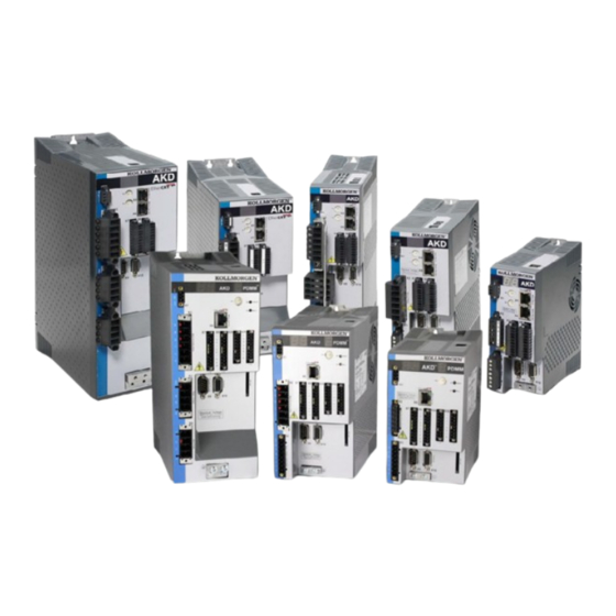
Page 30: The Akd Family Of Digital Drives
Regen circuit with dynamic distribution of the generated power between several drives on the same DC bus link circuit. Internal regen resistor for all 240/480 Vac AKD-xzzz07 models (only 120/240 Vac 3 A and 6 A AKD-xzzz06 models lack internal regen resistors), external regen resistors if required. - Page 31 Auxiliary supply voltage 24V DC From an external, safety approved 24 V ±10% power supply. Operation and parameter setting Using the setup software WorkBench for setup via TCP/IP or KAS IDE for AKD PDMM setup. Full digital control Digital current controller (670 ns) Adjustable digital velocity controller (62.5 µs)
-
Page 32: Ambient Conditions, Ventilation, And Mounting Position
AKD Installation | 6 Technical description and data 6.2 Ambient Conditions, Ventilation, and Mounting Position ➜ p. 18 Storage ➜ p. 18 Transport Ambient temperature 0 to +40 °C under rated conditions in operation +40 to +55 °C with continuous current derating 4 % per Kelvin... -
Page 33: Inputs/Outputs
AKD Installation | 6 Technical description and data 6.4 Inputs/Outputs Interface Electrical Data Analog inputs ±12 Vdc Common Mode Rejection Ratio: > 30 dB at 60 Hz resolution 16 bit and full monotonic nonlinearity < 0.1% of full scale offset drift max. 250µV/°C input impedance >... -
Page 34: Electrical Data Akd-Xzzz06
AKD Installation | 6 Technical description and data 6.5 Electrical Data AKD-xzzz06 AKD- AKD- AKD- AKD- Electrical Data Units x00306 x00606 x01206 x02406 3 x 120 V to 240 V ±10% 3x240 V Rated supply voltage 1 x 120 V to 240 V ±10% ±10%... -
Page 35: Electrical Data Akd-Xzzz07
AKD Installation | 6 Technical description and data 6.6 Electrical Data AKD-xzzz07 AKD- AKD- AKD- AKD- Electrical data Units x00307 x00607 x01207 x02407 Rated supply voltage 3 x 240 V to 480 V ±10% Rated supply input frequency AC with 50 Hz to 400 Hz ±5% or DC Rated input power for S1 operation 2.24... -
Page 36: Performance Data
AKD Installation | 6 Technical description and data 6.7 Performance Data AKD-xzzz06 Performance Data Units up to AKD- AKD- AKD- x00606 x01206 x02406 Switching frequency of output stage Voltage rise speed dU/dt kV/µs Bandwidth of current controller 2.5 to 4... -
Page 37: Fusing
I/O connector X7, X8 DCOM21, DCOM22 common line for digital inputs on I/O connector X21, X22 (I/O option card only) DCOM35, DCOM36 common line for digital inputs on I/O connector X35, X36(AKD-M only) 24 V supply, STO input, holding brake internal digital ground, encoder emulation output, service channel Kollmorgen™... -
Page 38: Connectors
AKD Installation | 6 Technical description and data 6.11 Connectors Given voltage and current data are the lowest values allowed by UL and CE. AKD-xzzz06 Types (120V to 240V Mains Voltage Supply) Connector Type Max. Cross Cur- Volt- Section rent Control signals X7/X8 Terminal Connector, 10 poles 1.5 mm², 16 awg 10 A... -
Page 39: Cable And Wire Requirements
AKD Installation | 6 Technical description and data 6.12 Cable and Wire Requirements 6.12.1 General For information on the chemical, mechanical, and electrical characteristics of the cables please refer to the accessories manual or contact customer support. To reach the maximum permitted cable length, you must use cable material with the fol-... -
Page 40: Dynamic Braking
Dynamic braking is a method to slow down a servo system by dissipating the mechanical energy driven by the motor back EMF. The AKD has a built in advanced dynamic braking mode which operates fully in hardware. When activated, the drive shorts the motor terminals in phase with the back EMF (q axis) but continues to operate the non-force producing current loop (d-axis) with 0 current. -
Page 41: Technical Data For Akd-Xzzz06
AKD Installation | 6 Technical description and data 6.13.1.2 Technical Data for AKD-xzzz06 Technical data for the regen circuit depends on the drive type and the mains voltage. Supply voltages, capacitances, and switch-on voltages are all nominal values. Observe the regeneration time (some minutes) for the dynamic brake circuit after full load with peak regen power. -
Page 42: Technical Data For Akd-Xzzz07
AKD Installation | 6 Technical description and data 6.13.1.3 Technical Data for AKD-xzzz07 Technical data for the regen circuit depends on the drive type and the mains voltage. Supply voltages, capacitances, and switch-on voltages are all nominal values. Observe the regeneration time (some minutes) after full load with peak regen power. -
Page 43: Switch-On And Switch-Off Behavior
AKD Installation | 6 Technical description and data 6.14 Switch-on and Switch-off Behavior This chapter describes the switch-on and switch-off behavior of the AKD. Behavior of “holding brake” function Drives with an enabled holding brake function have a special timing for switching on and off the output stage (➜... -
Page 44: Switch-On Behavior In Standard Operation
AKD Installation | 6 Technical description and data 6.14.1 Switch-on behavior in standard operation The diagram below illustrates the correct functional sequence for switching the drive on. Fault F602 occurs when STO (➜ p. 52) does not have current when HW enable becomes active. -
Page 45: Switch-Off Behavior
6.14.2.1 Switch-off behavior using the DRV.DIS command The enable/disable button in WorkBench issues a drv.dis command internally to the drive. See AKD User Guide for configuring inputs and software commands. Sometimes this enable signal is called "Software Enable" (SW-Enable). DRV.DISMODE DRV.DISMODE controls the behavior of the drv.dis command issued through WorkBench, or terminal, or fieldbus. -
Page 46: Switch-Off Behavior Using A Digital Input (Controlled Stop)
This is a category 2 stop according to IEC 60204 (➜ p. 50). A digital input can be configured to bring the motor to a controlled stop and then disable the drive and apply the holding brake.(if present). See the AKD User Guide for information on con- figuring Digital Inputs. -
Page 47: Switch-Off Behavior In The Event Of A Fault
The behavior of the drive always depends on the fault type and the setting of a number of dif- ferent parameters (DRV.DISMODE, VBUS.UVFTHRESH, CS.VTHRESH, and others; see the AKD User Guide or WorkBench help for more details).See the Drive Fault and Warning Messages and Remedies section of the AKD User Guide for a table describing the specific behavior of each fault. - Page 48 AKD Installation | 6 Technical description and data Switch-off behavior for faults that cause dynamic braking This is a category 0 stop according to IEC 60204 (➜ p. 50). If velocity drops below threshold CS.VTHRESH or timeout occurs brake is applied (➜...
- Page 49 AKD Installation | 6 Technical description and data Switch-off behavior for faults that cause a controlled stop This is a category 1 stop according to IEC 60204 (➜ p. 50). If velocity drops below threshold CS.VTHRESH or timeout occurs brake is applied (➜...
-
Page 50: Stop / Emergency Stop / Emergency Off
Notes for safety aspects of these functions can be found in ISO 13849 and IEC 62061. The parameter DRV.DISMODE must be set to 2 to implement the different stop categories. Consult the AKD User Guide for configuring the parameter. Functional safety, e.g. with hanging load (vertical axes), requires an addi- tional mechanical brake which must be safely operated, for example by a safety control. -
Page 51: Emergency Stop
AKD Installation | 6 Technical description and data 6.15.2 Emergency Stop The Emergency Stop function is used for the fastest possible shutdown of the machine in a dangerous situation. The Emergency Stop function is defined by IEC 60204. Principles of emergency stop devices and functional aspects are defined in ISO 13850. -
Page 52: Safe Torque Off (Sto)
Only low voltages are switched, so there is no contact wear. Very little wiring is required. The STO safety implemenation on the AKD is certified. The safety circuit implementation used for the safety function "Safe Torque Off" in the drive is suited for SIL 2 according to IEC 61508-2 and PLd / CAT3 according to ISO 13849-1. -
Page 53: Safety Instructions
AKD Installation | 6 Technical description and data 6.16.4 Safety instructions Drives with a suspended load must have an additional safe mechanical blocking (for instance, by a motor-holding brake). The drive cannot hold the load when STO is active. Serious injury could result when load is not properly blocked. -
Page 54: Technical Data And Pinning
AKD Installation | 6 Technical description and data 6.16.5 Technical data and pinning Signal Description +24 Vdc Auxiliary voltage 24V Supply GND STO enable (Safe Torque Off) 6.16.6 Enclosure, Wiring Since the drive meets IP20, you must select an enclosure that permits safe operation of the drive. -
Page 55: Signal Diagram (Sequence)
AKD Installation | 6 Technical description and data 6.16.7.1 Signal diagram (sequence) The diagram below shows how to use STO function for a safe drive stop and fault free oper- ation of the drive. 1. Brake the drive in a controlled manner (speed setpoint = 0 V). -
Page 56: Control Circuit (Example)
AKD Installation | 6 Technical description and data 6.16.7.3 Control circuit (example) The example shows a control circuit with two separated work areas connected to one emer- gency stop circuit (mains supply circuit: ➜ p. 57). For each work area, "safe stop" of the drives is switched by a protective screen. -
Page 57: Mains Supply Circuit (Example)
AKD Installation | 6 Technical description and data 6.16.7.4 Mains supply circuit (example) Corresponding control circuit ➜ p. 56. Kollmorgen™ | May 2013... -
Page 58: Shock-Hazard Protection
The AKD is a 3-phase system with a B6 bridge. Therefore, RCDs which are sensitive to all currents must be used in order to detect any DC fault current. Refer to the chapter above for the rule of thumb for determining the leakage current. -
Page 59: Mechanical Installation
AKD Installation | 7 Mechanical Installation 7 Mechanical Installation 7.1 Important Notes 7.2 Guide to Mechanical Installation 7.3 Mechanical Drawings Standard Width 7.4 Mechanical Drawings Extended Width Kollmorgen™ | May 2013... -
Page 60: Important Notes
7.2 Guide to Mechanical Installation The following tools are required (at a minimum) to install the AKD; your specific installation may require additional tools: M4 hexagon socket-cap screws (ISO 4762) 3 mm T-handle Allen key No. -
Page 61: Mechanical Drawings Standard Width
AKD Installation | 7 Mechanical Installation 7.3 Mechanical Drawings Standard Width 7.3.1 Control Cabinet Layout AKD-xzzz06, Standard Width Material: M4 hexagon socket screws to ISO 4762, 3 mm T-handle Allen key Kollmorgen™ | May 2013... -
Page 62: Control Cabinet Layout Akd-Xzzz07, Standard Width
AKD Installation | 7 Mechanical Installation 7.3.2 Control Cabinet Layout AKD-xzzz07, Standard Width Material: M4 hexagon socket screws to ISO 4762, 3 mm T-handle Allen key Kollmorgen™ | May 2013... -
Page 63: Dimensions Akd-Xzzz06, Standard Width
AKD Installation | 7 Mechanical Installation 7.3.3 Dimensions AKD-xzzz06, standard width Kollmorgen™ | May 2013... -
Page 64: Dimensions Akd-Xzzz07, Standard Width
AKD Installation | 7 Mechanical Installation 7.3.4 Dimensions AKD-xzzz07, standard width Kollmorgen™ | May 2013... -
Page 65: Mechanical Drawings Extended Width
AKD Installation | 7 Mechanical Installation 7.4 Mechanical Drawings Extended Width 7.4.1 Control Cabinet Layout, Example with AKD-M00306 Material: M4 hexagon socket screws to ISO 4762, 3 mm T-handle Allen key Kollmorgen™ | May 2013... -
Page 66: Control Cabinet Layout, Example With Akd-M00307
AKD Installation | 7 Mechanical Installation 7.4.2 Control Cabinet Layout, Example with AKD-M00307 Material: M4 hexagon socket screws to ISO 4762, 3 mm T-handle Allen key Kollmorgen™ | May 2013... -
Page 67: Dimensions Akd-Xzzz06, Extended Width
AKD Installation | 7 Mechanical Installation 7.4.3 Dimensions AKD-xzzz06, extended width Kollmorgen™ | May 2013... -
Page 68: Dimensions Akd-Xzzz07, Extended Width
AKD Installation | 7 Mechanical Installation 7.4.4 Dimensions AKD-xzzz07, extended width Kollmorgen™ | May 2013... -
Page 69: Electrical Installation
AKD Installation | 8 Electrical Installation 8 Electrical Installation 8.1 Important Notes 8.2 Guide to electrical installation 8.3 Wiring 8.4 Components of a servosystem 8.5 Connection Overview AKD-B, AKD-P, AKD-T 8.6 Connection Overview AKD-M 8.7 EMI Noise Reduction 8.8 Electrical Supply Connection 8.9 DC Bus Link (X3) -
Page 70: Important Notes
AKD Installation | 8 Electrical Installation 8.1 Important Notes Never remove electrical connections to the drive while it is live. There is a danger of electrical arcing with damage to contacts and serious personal injury. Wait at least seven minutes after disconnecting the drive from the main supply power before touching potentially live sections of the equip- ment (e.g. -
Page 71: Guide To Electrical Installation
Connect the auxiliary supply (maximum permissible voltage values see electrical data (➜ p. 34 or ➜ p. 35). Connect the mains filter with AKD-xzzz06 (shielded lines between filter and drive). Connect the main electrical supply. Check maximum permitted voltage value (➜ p. 34 or ➜ p. 35). Check proper use of residual-current circuit breakers (RCD): ➜... -
Page 72: Wiring
8.3 Wiring The installation procedure is described as an example. A different procedure may be appro- priate or necessary, depending on the application of the equipment. Kollmorgen™ can pro- vide training courses for this procedure upon request. There is a danger of electrical arcing which can cause serious personnel injury. -
Page 73: Components Of A Servosystem
AKD Installation | 8 Electrical Installation 8.4 Components of a servosystem With AKD-xzzz06 Cables drawn bold are shielded. Electrical ground is drawn with dash-dotted lines. Optional devices are connected with dashed lines to the drive. The required accessories are described in the accessories manual. - Page 74 AKD Installation | 8 Electrical Installation With AKD-xzzz07 Cables drawn bold are shielded. Electrical ground is drawn with dash-dotted lines. Optional devices are connected with dashed lines to the drive. The required accessories are described in the accessories manual. Kollmorgen™ | May 2013...
-
Page 75: Connection Overview Akd-B, Akd-P, Akd-T
AKD Installation | 8 Electrical Installation 8.5 Connection Overview AKD-B, AKD-P, AKD-T 8.5.1 Connector assignment AKD-x00306, AKD-x00606 The I/O option is available for AKD-T drives only. 8.5.2 Connector assignment AKD-x01206 The I/O option is available for AKD-T drives only. Kollmorgen™ | May 2013... -
Page 76: Connector Assignment Akd-X02406 And Akd-Xzzz07
AKD Installation | 8 Electrical Installation 8.5.3 Connector assignment AKD-x02406 and AKD-xzzz07 The I/O option is available for AKD-T drives only. Kollmorgen™ | May 2013... -
Page 77: Connection Diagram Akd-X00306, Akd-X00606
AKD Installation | 8 Electrical Installation 8.5.4 Connection Diagram AKD-x00306, AKD-x00606 The I/O option is available for AKD-T drives only. Kollmorgen™ | May 2013... -
Page 78: Connection Diagram Akd-X01206
AKD Installation | 8 Electrical Installation 8.5.5 Connection Diagram AKD-x01206 The I/O option is available for AKD-T drives only. Kollmorgen™ | May 2013... -
Page 79: Connection Diagram Akd-X02406 And Akd-Xzzz07
AKD Installation | 8 Electrical Installation 8.5.6 Connection Diagram AKD-x02406 and AKD-xzzz07 The I/O option is available for AKD-T drives only. Kollmorgen™ | May 2013... -
Page 80: Connection Overview Akd-M
AKD Installation | 8 Electrical Installation 8.6 Connection Overview AKD-M 8.6.1 Connector assignment AKD-M00306, AKD-M00606 8.6.2 Connector assignment AKD-M01206 Kollmorgen™ | May 2013... -
Page 81: Connector Assignment Akd-M00307, Akd-M00607, Akd-M01207
AKD Installation | 8 Electrical Installation 8.6.3 Connector assignment AKD-M00307, AKD-M00607, AKD-M01207 Kollmorgen™ | May 2013... -
Page 82: Connection Diagram Akd-M00306, Akd-M00606
AKD Installation | 8 Electrical Installation 8.6.4 Connection Diagram AKD-M00306, AKD-M00606 Kollmorgen™ | May 2013... -
Page 83: Connection Diagram Akd-M01206
AKD Installation | 8 Electrical Installation 8.6.5 Connection Diagram AKD-M01206 Kollmorgen™ | May 2013... -
Page 84: Connection Diagram Akd-M00307, Akd-M00607, Akd-M01207
AKD Installation | 8 Electrical Installation 8.6.6 Connection Diagram AKD-M00307, AKD-M00607, AKD-M01207 Kollmorgen™ | May 2013... -
Page 85: Emi Noise Reduction
Use Kollmorgen™ cables. Experience has shown that customers who use Kollmorgen™’s power and feedback cables have far fewer problems than customers who build cables. Route power and control cables separately, Kollmorgen™recommends a distance of at least 200 mm to improve interference immunity. -
Page 86: Shielding With External Shielding Busbar
AKD Installation | 8 Electrical Installation 8.7.2 Shielding with External Shielding Busbar EMC filtering must be done externally by the user if necessary, which requires the use of shielded cables.Kollmorgen™ recommends a star point shield connection, for example, with a shielding busbar. 8.7.2.1 Shielding Concept... -
Page 87: Shielding Busbar
AKD Installation | 8 Electrical Installation 8.7.2.2 Shielding Busbar The power cable shields (line in, motor cable, external regen resistor) can be routed to an additional busbar via shield clamps. Kollmorgen™ recommends using Weidmüller KLBÜ shield clamps. A possible scenario for setting up a busbar for the above shield clamps is described below. -
Page 88: Shielding Connection To The Drive
Use shield connection clamps (see accessories manual). These hook into the grounding plate and ensure optimum contact between the shield and the ground- ing plate. Kollmorgen™ recommends using Phoenix Contact SK14 shield clamps with clamp range of 6-13mm. 8.7.3.3 Motor Connector X2 with shielding connection Alternative connection for the motor power connection by mating connector with strain relief. -
Page 89: Electrical Supply Connection
AKD Installation | 8 Electrical Installation 8.8 Electrical Supply Connection 8.8.1 Connection to Various Mains Supply Networks AKD-xzzz06 (120V to 240V) This page illustrates all the possible connection variations for different electrical supply net- works. There is a danger of electrical shock with serious personnel injury if the drive is not properly grounded. -
Page 90: Connection To Various Mains Supply Networks Akd-Xzzz07 (240V To 480V)
AKD Installation | 8 Electrical Installation 8.8.2 Connection to Various Mains Supply Networks AKD-xzzz07 (240V to 480V) This page illustrates all the possible connection variations for different electrical supply net- works. There is a danger of electrical shock with serious personnel injury if the drive is not properly grounded. -
Page 91: Auxiliary Supply (X1)
AKD Installation | 8 Electrical Installation 8.8.3 24 V Auxiliary Supply (X1) The following diagram describes external 24 Vdc power supply, electrically isolated, for example, via an isolating transformer. The required current rating depends on the use of motor brake and option card ➜ p. 34 or ➜ p. 35). -
Page 92: Mains Supply Connection (X3, X4)
8.8.4.1 Three Phase connection (all AKD types) Directly to 3-phase supply network, supply networks ➜ p. 89 Filtering for AKD-xzzz06 to be provided by the user. Fusing (such as fusible cut-outs) to be provided by the user ➜ p. 37. -
Page 93: Single Phase Connection (Akd-X00306 To Akd-X01206 Only)
AKD Installation | 8 Electrical Installation 8.8.4.2 Single phase connection (AKD-x00306 to AKD-x01206 only) Directly to single-phase supply network (➜ p. 89 Supply networks ➜ p. 89 Leave L3 open circuit Filtering to be provided by the user. Fusing (such as fusible cut-outs) to be provided by the user ➜ p. 37... -
Page 94: Dc Bus Link (X3)
AKD Installation | 8 Electrical Installation 8.9 DC Bus Link (X3) The DC bus link can be connected in parallel so that the regen power is divided between all the drives that are connected to the same DC bus link circuit. Every drive must have it's own power connection to mains voltage, even if the DC bus link is used. -
Page 95: External Regen Resistor (X3)
AKD Installation | 8 Electrical Installation 8.9.1 External Regen Resistor (X3) For technical data on the brake circuit "Dynamic Braking" (➜ p. 40). Fusing (such as fusible cut-outs) to be provided by the user "Fusing" (➜ p. 37). AKD-x00306 to AKD-x00606 (X3) -
Page 96: Capacitor Modules (X3)
The modules can be combined as required. The KCM modules may only be connected to AKD with 400/480 V rated voltage and a max- imum rated current of 24 A. Mounting, installation, and setup instructions can be found in the Instructions Manual of the KCM Modules. -
Page 97: Example Installation With Kcm-S And Kcm-E
DC+/DC- will damage the KCM modules. Connect the BR connection to theAKD with the most frequent generative braking processes in the system. This AKD must have an active internal or external brake resistor. Create a motion profile that causes the brake chopper to respond. -
Page 98: Example Installation With Kcm-P And Kcm-E
AKD Installation | 8 Electrical Installation 8.9.2.3 Example installation with KCM-P and KCM-E Maximum cable length between AKD and KCM: 500mm. The DC+ and DC- lines should always be twisted, maximum cross section is 6mm². Ensure that the polarity is correct, swapping round DC+/DC- will damage the KCM modules. -
Page 99: Discharging Kcm Modules
AKD Installation | 8 Electrical Installation 8.9.2.4 Discharging KCM modules The aids supplied with each KCM module (plug-in bridge/connecting cables) allows dis- charging the modules safely. When the charging LED on top of the modules flashes, the capacitors are charged. Please note, however, that the LED does not allow you to draw a definite conclusion about the state of discharge, as it is not monitored for failures. -
Page 100: Motor Connection
AKD Installation | 8 Electrical Installation 8.10 Motor Connection Together with the motor supply cable and motor winding, the power output of the drive forms an oscillating circuit. Characteristics such as cable capacity, cable length, motor inductance, and frequency (➜ p. 34 or ➜ p. 35) determine the maximum voltage in the system. -
Page 101: Motor Power (X2)
AKD Installation | 8 Electrical Installation 8.10.1 Motor Power (X2) 8.10.1.1 Cable Length ≤ 25 m 8.10.1.2 Cable length >25 m With long motor cables leakage currents endanger the output stage of the drive. For cable lengths from 25 m to 50 m, a motor choke must be wired into the motor cable (near the drive). -
Page 102: Motor Holding Brake (X2)
AKD Installation | 8 Electrical Installation 8.10.2 Motor Holding Brake (X2) A 24 V holding brake in the motor can be controlled directly by the drive. The brake only works with sufficient 24 V voltage level (➜ p. 34 or ➜ p. 35). Check voltage drop, measure the voltage at brake input and check brake function (brake and no brake). -
Page 103: Feedback Connection
AKD supports the most common types of feedback device. Two feedback devices can be used at the same time, and all feedbacks are connected to X10. Feedback functions are assigned with parameters in WorkBench, the setup software. -
Page 104: Feedback Connector (X10)
AKD Installation | 8 Electrical Installation 8.11.1 Feedback Connector (X10) Sine Tama- Incr. BiSS A BiSS C EnDAT EnDAT Hiper- Resolver Enc. gawa Enc. (analog) (digital) face +Hall Smart Abs +Hall Hall U Hall U CLK+ CLK+ CLK+ CLK+ Hall V... -
Page 105: Resolver
If cable lengths of more than 100 m are planned, please contact customer support. Type FBTYPE Description Resolver Accuracy: 14 bit (0.022°), resolution: 16 bit (0.006°) The pin assignment shown on the resolver side relates to Kollmorgen™ motors. Kollmorgen™ | May 2013... -
Page 106: Sfd
AKD Installation | 8 Electrical Installation 8.11.3 SFD The diagram below shows the connection of the Kollmorgen™ feedback system. When SFD cable total resistance for 5V out (Up) and 5V return (0V) is less than 3.3 Ohm, then remote sensing is not needed. For typical cable this means remote sensing is not needed up to 25 m. -
Page 107: Hiperface Dsl
AKD Installation | 8 Electrical Installation 8.11.4 Hiperface DSL The diagram below shows the connection of the two wire Hiperface DSLfeedback system. Hiperface DSL can be used with the special Kollmorgen™ cable. Maximum cable length is up to 25 m. Type... -
Page 108: Encoder With Biss
If cable lengths of more than 50 m are planned, please consult customer support. Type FBTYPE Frequency Limit BiSS (Mode A) Analog 5.1 V +/-5% 1 MHz The pin assignment shown on the encoder side relates to Kollmorgen™ motors. Kollmorgen™ | May 2013... -
Page 109: Biss (Mode C) Digital
If cable lengths of more than 25 m are planned, please consult customer support. Type FBTYPE Frequency Limit BiSS Mode C 5.1 V +/-5% 2.5 MHz The pin assignment shown on the encoder side relates to Kollmorgen™ motors. Kollmorgen™ | May 2013... -
Page 110: Sine Encoder With Endat
All signals are connected using our pre-assembled encoder connection cable. If cable lengths of more than 50 m are planned, consult customer support. Type FBTYPE Frequency Limit ENDAT 2.1 1 MHz The pin assignment shown on the encoder side relates to Kollmorgen™ motors. Kollmorgen™ | May 2013... -
Page 111: Encoder With Endat
If cable lengths of more than 50 m are planned, please consult customer support. Type FBTYPE Frequency Limit Description ENDAT 2.2 1 MHz Adjust on screen page FEEDBACK The pin assignment shown on the encoder side relates to Kollmorgen™ motors. Kollmorgen™ | May 2013... -
Page 112: Sine Encoder With Hiperface
If cable lengths of more than 50 m are planned, please consult customer support. Type FBTYPE Frequency Limit Description Hiperface 1 MHz Connecting pin 4 and 5 together causes Up to be 8 to 9 V The pin assignment shown on the encoder side relates to Kollmorgen™ motors. Kollmorgen™ | May 2013... -
Page 113: Sine Encoder
Feedback devices, which do not deliver absolute information for commutation, can either work with wake&shake commutation (see AKD User Guide) or can be used as a complete feedback system when combined with an additional Hall encoder. All signals are connected to X10 and evaluated there. -
Page 114: Incremental Encoder
Feedback devices, which do not deliver absolute information for commutation, can either work with wake&shake commutation (see AKD User Guide) or can be used as a complete feedback system when combined with an additional Hall encoder. All signals are connected using a pre-assembled comcoder connection cable. -
Page 115: Tamagawa Smart Abs Encoder
AKD Installation | 8 Electrical Installation 8.11.11 Tamagawa Smart Abs Encoder The diagram below shows the wiring of Tamagawa "Smart Abs" encoders (Tamagawa Seiki Co. Ltd. S48-17/33bit-LPS-5V or similar) as a primary feedback system. The thermal control in the motor is connected via the encoder cable and evaluated in the drive. If no thermal con- trol is in the motor, the cable must short pins 8 and 9. -
Page 116: Electronic Gearing, Master-Slave Operation
AKD Installation | 8 Electrical Installation 8.12 Electronic gearing, Master-slave operation It is possible to set up master/slave systems, use an external encoder as a command encoder, secondary feedback device (dual loop control) or connect the amplifier to a third party step controller. -
Page 117: Connector X9 Input
AKD Installation | 8 Electrical Installation 8.12.1.2 Connector X9 Input Technical characteristics Electrical interface: RS-485 Maximum signal input frequency: 3MHz Input signal voltage range: +12 V to -7 V Supply voltage (only applicable to Incremental Encoder Input): +5 V ±5% Maximum supply current: 250 mA... -
Page 118: Command Encoder Signal Connection
AKD Installation | 8 Electrical Installation 8.12.2 Command encoder signal connection 8.12.2.1 Incremental encoder input 5 V (X9) A 5 V A quad B encoder, or the encoder emulation output of another drive can be connected to this input and used as a commander encoder, dual loop feedback, gearing or camming input. -
Page 119: Encoder With Endat 2.2 Input 5 V (X9)
AKD Installation | 8 Electrical Installation 8.12.2.3 Encoder with EnDat 2.2 input 5 V (X9) A single-turn or multi-turn encoder with EnDat 2.2 can be connected to this input and used as a commander encoder, dual loop feedback, gearing or camming input. Don't use for primary... -
Page 120: Pulse / Direction Signal Connection
AKD Installation | 8 Electrical Installation 8.12.3 Pulse / Direction signal connection The drive can be connected to a stepper-motor controller. Set parameters for the drive with WorkBench. The number of pulses can be adjusted, so that the drive can be adapted to match any stepper controller. -
Page 121: Up / Down Signal Connection
AKD Installation | 8 Electrical Installation 8.12.4 Up / Down signal connection 8.12.4.1 Up / Down input 5 V (X9) The drive can be connected to a third-party controller which delivers 5 V up-down signals 8.12.4.2 Up / Down input 24 V (X7) The drive can be connected to a third-party controller which delivers 24 V up-down signals. -
Page 122: Emulated Encoder Output (Eeo)
AKD Installation | 8 Electrical Installation 8.12.5 Emulated Encoder Output (EEO) The drive calculates the motor shaft position from the cyclic- absolute signals of the primary feedback, generating incremental-encoder compatible pulses from this information. Pulse out- puts on the SubD connector X9 are 3 signals, A, B and Index, with 90° phase difference (i.e. -
Page 123: Master-Slave Control
AKD Installation | 8 Electrical Installation 8.12.6 Master-Slave Control Several AKD can be connected as slave drives to an AKD master. The slave drives use the master's encoder output signals as command input and follow these commands (velocity and direction). -
Page 124: I/O Connection
AKD Installation | 8 Electrical Installation 8.13 I/O Connection 8.13.1 I/O Connectors X7 and X8 (all AKD variants) Standard digital and analog I/O signals are connected to X7 and X8. AKD-B, -P, -T Conn. Signal Abbreviation Function Wiring Diagram ➜ p. 130... -
Page 125: I/O Connectors X21, X22, X23 And X24 (Akd-T With I/O Option Card Only)
AKD Installation | 8 Electrical Installation 8.13.2 I/O Connectors X21, X22, X23 and X24 (AKD-T with I/O option card only) The I/O option card offers four additional connectors X21, X22, X23, X24 for I/O signals. AKD-xyyyzz-IC Conn. Signal Abbreviation Function... - Page 126 AKD Installation | 8 Electrical Installation Conn. Signal Abbreviation Function Wiring Diagram ➜ p. 129 Analog Output 2 + Analog-Out2 Programmable reserved n.c. n.c. Analog Ground AGND Programmable reserved n.c. n.c. ➜ p. 137 Digital Output 21+ DIGITAL-OUT 21+ Programmable...
-
Page 127: I/O Connectors X35 And X36 (Akd-M Only)
AKD Installation | 8 Electrical Installation 8.13.3 I/O Connectors X35 and X36 (AKD-M only) AKD PDMM offers two additional connectors X35 and X36 for digital I/O signals. AKD-M Conn. Signal Abbreviation Function Wiring Dia- gram ➜ p. 139 Digital Common X35... -
Page 128: Analog Input (X8, X24)
AKD Installation | 8 Electrical Installation 8.13.4 Analog Input (X8, X24) The drive is fitted with differential inputs for analog torque, velocity, or position control. The standard drive offers one analog input on X8, drives with built-in I/O option card offer a sec- ond input on X24. -
Page 129: Analog Output (X8, X23)
AKD Installation | 8 Electrical Installation 8.13.5 Analog Output (X8, X23) Analog Outputs can be used to output converted analog values of digital measurements recorded in the drive. The standard drive offers one analog output on X8, drives with built-in I/O option card offer a second output on X23. -
Page 130: Digital Inputs (X7/X8)
AKD Installation | 8 Electrical Installation 8.13.6 Digital Inputs (X7/X8) The drive provides 8 digital inputs (➜ p. 124). These can be used to initiate pre-programmed functions that are stored in the drive. A list of these pre-programmed functions is included in the WorkBench. - Page 131 AKD Installation | 8 Electrical Installation Digital Input Wiring Diagram (Sink type connection, example) Kollmorgen™ | May 2013...
-
Page 132: Digital Inputs 1 And
AKD Installation | 8 Electrical Installation 8.13.6.1 Digital Inputs 1 and 2 These inputs (X7/9 and X7/10) are particularly fast and are therefore suitable for latch func- tions, for example. They can also be used as 24 V inputs for electronic gearing (➜ p. 116). -
Page 133: Digital Outputs (X7/X8)
AKD Installation | 8 Electrical Installation 8.13.7 Digital Outputs (X7/X8) 8.13.7.1 Digital Outputs 1 and 2 The drive supplies 2 digital outputs (X7/5 to X7/8, ➜ p. 124). Choose the required function in the setup software. Messages from pre-programmed functions stored in the drive can be out- put here. -
Page 134: Fault Relay Contacts
AKD Installation | 8 Electrical Installation 8.13.7.2 FAULT relay contacts Operational readiness (terminals X8/1 and X8/2 ) is signaled by a floating relay contact. The fault relay can be programmed to two modes of operation: - Contact closed when there is no fault - Contact closed when there is no fault and the drive is enabled. -
Page 135: Digital Inputs With I/O Option (X21, X22)
AKD Installation | 8 Electrical Installation 8.13.8 Digital Inputs with I/O option (X21, X22) The drive option "IC" provides12 additional digital inputs (➜ p. 124). These can be used to ini- tiate pre-programmed functions that are stored in the drive. A list of these pre-programmed functions is included in WorkBench. - Page 136 AKD Installation | 8 Electrical Installation Digital Input Wiring Diagram (Sink type connection, example) Kollmorgen™ | May 2013...
-
Page 137: Digital Outputs With I/O Option (X23/X24)
AKD Installation | 8 Electrical Installation 8.13.9 Digital Outputs with I/O option (X23/X24) 8.13.9.1 Digital Outputs 21 to 24, 26 to 29 The drive option "IC" provides 10 digital outputs (➜ p. 124). Choose the required function in the setup software. Messages from pre-programmed functions stored in the drive can be out- put here. -
Page 138: Digital Relay Outputs
AKD Installation | 8 Electrical Installation 8.13.9.2 Digital Relay Outputs 25, 30 The drive option "IC" provides two digital outputs, which are signaled by floating relay con- tacts(➜ p. 124). Choose the required function in the setup software. Messages from pre-pro- grammed functions stored in the drive can be output here. -
Page 139: Digital Inputs (X35/X36) With Akd-M
8.13.10 Digital Inputs (X35/X36) with AKD-M In addition to the 8 digital inputs on X7 and X8 (➜ p. 124), the AKD PDMM provides 6 digital inputs on X35 and X36. These can be used to initiate pre-programmed functions that are stored in the drive. - Page 140 AKD Installation | 8 Electrical Installation Digital Input Wiring Diagram (Sink type connection, example) Kollmorgen™ | May 2013...
-
Page 141: Digital Outputs (X35/X36) With Akd-M
In addition to the 2 digital outputs on X7 ( ➜ p. -
Page 142: Led Display
AKD two digits AKD-M two + one digits AKD fault codes or warning codes The two digits LED display indicates the AKD mes- are displayed constantly if present. sages. Fault messages are coded with "F", warnings Fault messages are coded with "F"... -
Page 143: Rotary Switches (S1, S2, Rs1)
8.15 Rotary Switches (S1, S2, RS1) Rotary switches can be used to select IP address or predefined funtions for executing. AKD S1, S2 AKD PDMM RS1 8.15.1 Rotary switches S1 and S2 with AKD-B, -P, -T S1 S2 Function Set while Remarks... -
Page 144: Pushbuttons (B1, B2, B3)
AKD Installation | 8 Electrical Installation 8.16 Pushbuttons (B1, B2, B3) The pushbuttons can be used to start predefined functions. 8.16.1 Pushbutton B1 with AKD-B, -P, -T Function Pushbutton Remarks Display IP address Press short to display the IP address in the two digit dis-... -
Page 145: Pushbuttons B1, B2, B3 With Akd-M
AKD Installation | 8 Electrical Installation 8.16.2 Pushbuttons B1, B2, B3 with AKD-M Function Pushbutton Remarks Unused Boot-time functions (press and hold button during power-on boot sequence) Recovery Press and hold to boot into recovery mode. Mode Menu Press and hold to block the application auto-start and to start cycling through the menu items. -
Page 146: Sd Card Slot
8.17.1 SD Card Slot with I/O option card Drives with I/O option card offer a SD card slot to activate file transfers from/to the AKD and SD Memory Card. These features can be started from the WorkBench software or with push- button B1 (top of the drive) combined with rotary switch setting 10 or 11. -
Page 147: Sd Card Slot With Akd-M
AKD Installation | 8 Electrical Installation 8.17.2 SD Card Slot with AKD-M AKD PDMM offers a SD card slot and pushbuttons B2 and B3 to activate file transfers from/to the AKD PDMM and SD Memory Card. These features can be started from the KAS IDE software as well. -
Page 148: Service Interface (X11, X32)
Use standard Cat. 5 Ethernet cables for connection (in some cases crossover cables will also work). Confirm that the link LED on the AKD (the green LED on the RJ45 connector) and on your PC (or network Hub/Switch) are both illuminated. If both lights are illuminated, then you have a good electrical connection. -
Page 149: Setting The Ip Address Akd-B, Akd-P, Akd-T
The IP address can be flashed across the LED display if the B1 button is pressed. You can use the rotary switches to set the IP address of the AKD. For CANopen and some other fieldbuses, the rotary switches also set the node address of the drive for that specific network. - Page 150 By default, the drive utilizes the method described above to aquire its IP address. A method of setting the IP address independent of the Rotary switches is available. More information is available in the AKD User Guide or in the Settings Screen-> Fieldbus-> TCP/IP screen in WorkBench.
-
Page 151: Setting The Ip Address Akd-M
8.18.5 Setting the IP Address AKD-M You can use the rotary switch RS1 to set the IP address of the AKD PDMM. The configured IP address (depending on the current rotary switch RS1 position) will be displayed on the 7 segment at Ethernet cable connection time and at power-on, if an Ethernet cable is con- nected.. -
Page 152: Modbus Tcp
HMI’s IP address. The last octet must be different. Confirm that the link LED on the AKD (the green LED on the RJ45 connector) and on your Master or Switch are both illuminated. If both lights are illuminated, then you have a good electrical connection. -
Page 153: Can-Bus Activation With Akd-Cc Models
The following steps are needed for changing the fieldbus type from EtherCAT to CAN with the rotary switches. 1. Set the rotary switches on the front side of the AKD to the value of 89. Set S1 to 8 and S2 to 9 2. -
Page 154: Baudrate For Can-Bus
The transmission rate can be set via the parameter FBUS.PARAM01. The parameter FBUS.PARAM01 can either be set via WorkBench or via a special mechanism with the rotary switches in the AKD front. Baudrate Upper rotary... -
Page 155: Node Address For Can-Bus
The last bus device on both ends of the CAN-Bus system must have termination resistors. The AKD has built-in 132 ohms resistors that can be activated by connecting pins 1 and 6. An optional termination plug is available for AKD (P-AKD-CAN-TERM). The optional ter- mination plug is an RJ-12 connector with an enclosed wire jumper between pins 1&6. -
Page 156: Can-Bus Wiring
AKD Installation | 8 Electrical Installation 8.19.6 CAN-Bus Wiring Kollmorgen™ | May 2013... -
Page 157: Motion Bus Interface (X5/X6/X11)
AKD Installation | 8 Electrical Installation 8.20 Motion Bus Interface (X5/X6/X11) The motion bus interface has RJ-45 connectors and can be used for communicating with var- ious fieldbus devices depending on the used drive version. AKD X5/X6 AKD PDMM X6 Do not connect the Ethernet line for the PC or PAC with the set up software to the motion bus interface X5/X6. -
Page 158: Ethercat
The following steps are needed for changing the fieldbus type from CAN to EtherCAT with the rotary switches. 1. Set the rotary switches on the front side of the AKD to the value of 89. Set S1 to 8 and S2 to 9 2. -
Page 159: Synqnet
Use standard Cat. 5 Ethernet cables for connection. Confirm that the link LED on the AKD (the green LED on the RJ45 connector) and on your Master or Switch are both illuminated. If both lights are illuminated, then you have a good electrical connection. -
Page 160: Setup
AKD Installation | 9 Setup 9 Setup 9.1 Important Notes 9.2 Setup AKD-B, AKD-P, AKD-T 9.3 Setup AKD-M 9.4 Fault and Warning Messages 9.5 Troubleshooting the AKD Kollmorgen™ | May 2013... -
Page 161: Important Notes
Programming parameters and control loop behavior are described in the online help of the setup software. The setup of any expansion card described in the corresponding manual on the DVD. Kollmorgen™can provide training courses for the drive upon request. Kollmorgen™ | May 2013... -
Page 162: Setup Akd-B, Akd-P, Akd-T
The setup software is intended to be used for altering and saving the operating parameters for the AKD series of drives. The attached drive can be set up with the help of this software, and during this procedure the drive can be controlled directly by the service functions. -
Page 163: Software Description
The PC is connected to the drive by an Ethernet cable (➜ p. 148). The setup software provides the communication between the PC and AKD. You can find the setup software on the accompanying DVD and in the download area of the Koll- morgen™... -
Page 164: Installation Under Windows 2000/Xp/Vista/7
Click OK and proceed as described above. Connection to the Ethernet interface of the PC Connect the interface cable to an Ethernet interface on your PC or to a Hub/Switch and to the service interface X11 of the AKD (➜ p. 148). Kollmorgen™ | May 2013... -
Page 165: Initial Drive Test Akd-B, Akd-P, Akd-T
This wiring diagram is for general illustration only and does not fulfill any requirements for EMC, safety, or functionality of your application. When connecting the AKD directly to a PC, static IP addressing (not 00) is recommended. Kollmorgen™ | May 2013... -
Page 166: Set Ip Address
AKD Installation | 9 Setup 9.2.7.3 Set IP Address Set the drive IP address as described in "Setting the IP Address AKD-B, AKD-P, AKD-T" (➜ p. 149). 9.2.7.4 Confirm Connections You can turn on logic power to the drive through the X1 connector (bus voltage is not needed for communications). -
Page 167: Install And Start Workbench
9.2.7.7 Enable the Drive Using the Setup Wizard Once a connection to the drive has been established, the AKD Overview screen appears. Your drive appears in the navigation area on the left of the screen. Right click on your drive name and select Setup Wizard from the drop-down menu. -
Page 168: Setup Akd-M
The setup software is intended to be used for altering and saving the operating parameters for the AKD PDMM series of drives. The attached drive can be set up with the help of this soft- ware, and during this procedure the drive can be controlled directly by the service functions. -
Page 169: Software Description
Ethernet cable (➜ p. 148). The setup software provides the com- munication between the PC and AKD PDMM. You can find the KAS IDE setup software on the accompanying DVD and in the download area of the Kollmorgen™ website. -
Page 170: Installation Under Windows Xp/7
Connection to the Ethernet interface of the PC Connect the interface cable to an Ethernet interface on your PC or to a Hub/Switch and to the service interface X32 of the AKD PDMM (➜ p. 148). Kollmorgen™ | May 2013... -
Page 171: Initial Drive Test Akd-M
This wiring diagram is for general illustration only and does not fulfill any requirements for EMC, safety, or functionality of your application. When connecting the AKD PDMM directly to a PC, static IP addressing (not 0) is rec- ommended. Kollmorgen™ | May 2013... -
Page 172: Set Ip Address
AKD Installation | 9 Setup 9.3.7.3 Set IP Address Set the drive IP address as described in "Setting the IP Address AKD-M" (➜ p. 151). 9.3.7.4 Confirm Connections You can turn on logic power to the drive through the X1 connector (bus voltage is not needed for communications). -
Page 173: Install And Start Kas Ide
AKD Installation | 9 Setup 9.3.7.5 Install and Start KAS IDE The KAS IDE is included on the DVD that came with the AKD PDMM, as well as online at www.kollmorgen.com. Insert the DVD and wait for installer to auto-start. Once installation is complete, click the KAS IDE icon to start the program. -
Page 174: Set Drive Ip Address In Kas Ide
IP address in sequence (for example, 192.168.0.105). 2. The IP address of the AKD PDMM is setup in the project file inside the KAS IDE. To see the IP address, open a project or create a new project. Right click on the Project Explorer/Project view Controller item and select Properties. -
Page 175: Starting New Project
Once a project (new or saved) is opened from the Project Explorer, you can open a variety of items to build a project: All drives, including the drive in the AKD PDMM itself, and the Remote I/O can be configured by the KAS IDE. - Page 176 AKD Installation | 9 Setup To communicate directly with a drive without running a project click on the EtherCAT item in the project tree. Click on the drive in the project tree to configure (1), then click on the Online...
- Page 177 AKD Installation | 9 Setup To perform basic motion without running a project the Service Motion screen can be used. Kollmorgen™ | May 2013...
-
Page 178: Fault And Warning Messages
1-0-1-[break]. The highest priority fault is displayed. Multiple faults may be present when a fault condition is occurring. Check the AKD Work- Bench Fault Screen or read the status of DRV.FAULTS through the controller or HMI for the entire list of faults. - Page 179 AKD Installation | 9 Setup Fault Message/Warning Cause n102 Operational FPGA is not a default The FPGA minor version is larger than the operational FPGA. firmware default FPGA minor version F103 Resident FPGA failed. Software failure detected. Load resident FPGA failure occurred (several cases according to flowchart, including incompatible image to FPGA type and fieldbus type).
- Page 180 AKD Installation | 9 Setup Fault Message/Warning Cause n151 Not enough distance to move; motion For trapezoidal and customer table motion tasks: The tar- exception. get velocity specified in the motion task cannot be reached via using the selected acceleration and decel- eration since the distance to travel is not sufficient.
- Page 181 AKD Installation | 9 Setup Fault Message/Warning Cause n170 Customer profile table is not initial- Appears with n160, when you try to trigger a motion task ized. that uses a customer profile table for generating the veloc- ity profile and when the selected profile table is empty (see MT.CNTL and MT.TNUM.
- Page 182 Tamagawa encoder: battery. The external battery voltage is too low. F451 fault is gen- n451 erated if the AKD is not powered. The n451 warning is generated if the AKD is powered. This fault can be inhib- ited with FAULT451.ACTION.
- Page 183 AKD Installation | 9 Setup Fault Message/Warning Cause F461 Tamagawa encoder: counting Error. When the feedback is powered on the position (within on revolution) was incorrect because of a problem with the feedback device. F462 Tamagawa encoder: counting over- Multi-turn counter has overflowed.
- Page 184 AKD Installation | 9 Setup Fault Message/Warning Cause F493 Invalid commutation detected – A commutation error occured when current has another motor accelerating in the wrong direc- sign than accelaration and velocity over a defined time. tion. F501 Bus over voltage.
- Page 185 AKD Installation | 9 Setup Fault Message/Warning Cause F703 Emergency timeout occurred while Motor did not stop in the timeout defined. axis should disable n704 PVT buffer overflow in process. n705 PVT buffer underflow in process. Kollmorgen™ | May 2013...
-
Page 186: Additional Fault Messages Akd-T
AKD Installation | 9 Setup 9.4.2 Additional Fault Messages AKD-T AKD BASIC runtime faults are displayed in the two-digits 7-segment display of the drive: The two digits LED display indicates the fault code. The additional runtime fault messages for AKD-T are coded with numbers starting from F801. -
Page 187: Additional Error And Alarm Messages Akd-M
AKD Installation | 9 Setup 9.4.3 Additional Error and Alarm Messages AKD-M Faults/Errors and Warnings/Alerts are displayed in the 7 segment displays of the drive: AKD two digits AKD-M two + one digits The two digits LED display indicates The one digit LED indicates the the AKD messages. - Page 188 AKD Installation | 9 Setup Error Description Cause Remedy E12 Not enough flash Flash memory is full, unable to Clean-up the flash memory by removing log files, memory available. write to flash. application programs, recipes, or other data files. E13 Out of NVRAM NVRAM is full.
-
Page 189: Alarms
AKD Installation | 9 Setup Error Description Cause Remedy E32 EtherCAT com- EtherCAT network operation Check the EtherCAT network wiring and devices munication failure failed due to a network com- state. Re-start the application. during bootstrap munciation error. mode. E33 EtherCAT failed to... - Page 190 AKD Installation | 9 Setup Alarm Description Cause Remedy CPU is overloaded Reduce the sample rate, simplify the appli- cation, or reduce the application cycles. EtherCAT missed a EtherCAT master was unable to Reduce the controller CPU load. send frame during oper- send a frame for one or more ation mode.
-
Page 191: Troubleshooting The Akd
AKD Installation | 9 Setup 9.5 Troubleshooting the AKD Drive problems occur for a variety of reasons, depending on the conditions in your instal- lation. The causes of faults in multi-axis systems can be especially complex. If you cannot resolve a fault or other issue using the troubleshooting guidance presented below, customer support can give you further assistance. -
Page 192: Record Of Document Revisions
EnDat 2.2 @ X9, STOP chapter updated, dimension draw- ings H, 05/2012 AKD-T-IC added, I/O option card signals added , PDMM error codes updated J, 08/2012 Smart Abs (Tamagawa) new, BiSS C new, X21 & X22 pinout updated... -
Page 193: Index
AKD Installation | 11 Index Dynamic Braking 11 Index EC Declaration of Conformity Emergency Off Abbreviations Emergency Stop Function AKD Family Emulated Encoder Connector Ambient temperature Emulated Encoder Output Analog inputs ENABLE Analog setpoints Enclosure protection Aux. supply 24V, interface EnDat 2.1 encoder interface... -
Page 194: Kollmorgen™ | May
AKD Installation | 11 Index Digital all Variants Part number scheme Digital M Variant PC connection Digital, I/O option Pollution level Enable PROFINET Programmable 132, 135 Prohibited Use General Installation Electrical Pulse Direction, interface Mechanical Pushbuttons Software KAS IDE Software WorkBench... - Page 195 AKD Installation | 11 Index Temperature in operation Storage Transport Tightening torques, connectors Transport Trouble Shooting UL Markings Uninstalling Up/Down Input Use as directed Drive KAS IDE Setup Software WorkBench Setup Software Ventilation Ambient Conditions Mechanical Installation Vibrations Warnings Wiring...
- Page 196 About KOLLMORGEN Kollmorgen is a leading provider of motion systems and components for machine builders. Through world- class knowledge in motion, industry-leading quality and deep expertise in linking and integrating standard and custom products, Kollmorgen delivers breakthrough solutions that are unmatched in performance, reliability and ease-of-use, giving machine builders an irrefutable marketplace advantage. ...
Need help?
Do you have a question about the AKD and is the answer not in the manual?
Questions and answers