Sign In
Upload
Manuals
Brands
Kollmorgen Manuals
Servo Drives
AKD series
Kollmorgen AKD series Manuals
Manuals and User Guides for Kollmorgen AKD series. We have
7
Kollmorgen AKD series manuals available for free PDF download: User Manual, Installation Manual, Manual, Training Manual
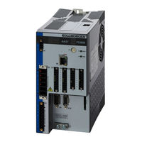
Kollmorgen AKD series User Manual (906 pages)
Brand:
Kollmorgen
| Category:
DC Drives
| Size: 8 MB
Table of Contents
Table of Contents
3
1 About this User Guide
27
Abbreviations
27
2 AKD Models
28
CC Drive Models
28
Basic Drive Setup
29
Display Codes
30
3 Basic Drive Setup
30
AKD Setup Wizard
31
4 Connecting the Drive
33
Connected and Disconnected States
34
Disconnected
34
Device Not Shown
34
Find and Enter IP Address
35
Check Communications
36
Connect to Another Drive
36
5 Communicating with the Drive
37
Overview
38
Identifying the Drive IP Address
38
Automatic (Dynamic) IP Addressing
38
Static IP Addressing
38
Check Communications
39
Troubleshooting Connection and Communication Problems
41
No Drives Are Shown
42
Device Not Shown
42
Find and Enter IP Address
42
TCP/IP Communication Protocols
44
IP Address
44
Port Number
44
MAC Address
44
6 Using Workbench
45
Welcome Screen
45
Online
45
Offline
46
AKD Overview
46
Online and Offline
47
Online Drive
47
Offline Drive
47
Switching between Online and Offline
48
Watch
48
Settings
48
Navigation Tree
48
Settings View
48
7 Configuring Drive Power
51
Power
52
Drive Setup for Power and Bus
52
Direct DC Mains Operation
52
Regeneration
54
Overview
54
Regen Resistor Options
54
Calculating Motor Peak Energy and Regen Resistor Size
54
Kollmorgen | December
55
Selecting a Compatible Regen Resistor
57
Configuring Regen Parameter Values
57
Related Parameters
58
8 Configuring Motor Settings
59
Motor
60
Overview
60
Motor Setup
60
Using the Motor View
60
Selecting a Motor
61
Configuring Custom Motors
62
Validating Motor Parameters
62
Feedback
62
Overview
63
Using Feedback Options
63
Auto
63
Incremental Encoder
63
Sine Encoder
63
Endat 2.1, Endat
63
Biss
63
Hiperface
63
Resolver
64
Sfd
64
Using Wake and Shake (WS)
64
Configuring WS
64
Overview
64
Operation with Motor Brake
65
Special Cases for WS
65
Wake and Shake, more View
65
End of Travel Limits
66
Large Load Inertia or High Friction System
66
Maximizing WS Reliability
66
Using WS: Advanced
66
Related Parameters
67
Troubleshooting WS
67
Commutation Alignment 8.4 Feedback
68
Feedback 2
68
Encoder Emulation
69
Function Settings
69
Mode 0: Disable X9
69
Output Modes 1 and 2
69
Overview
69
Using Encoder Emulation
69
Input Modes 3, 4, and
70
Kollmorgen | December
70
Related Parameters and Commands
71
Resolution
71
Non-Plug and Play Feedback Devices
71
Parameters
71
Calculations
72
Current Loop
72
Velocity Loop
72
Position Loop
72
Slider Tuning
72
Constants
72
Input - Motor Data
72
Output - Control Loop Gains
72
Foldback
72
Drive Foldback
73
Setting up Motor Foldback
73
Setting Fault and Warning Levels
73
Motor Peak Current Time
74
Motor Foldback Ramp
74
Motor Recovery
75
Overall Foldback
75
Brake
76
Using Position Capture
76
Overview
76
Configuring Position Capture
76
Arming and Retrieving the Capture Value (CAP0.EN and CAP0.T)
77
Setting the Capture Edge (CAP0.EDGE)
77
Setting the Capture Mode (CAP0.MODE)
77
Setting the Capture Source (CAP0.TRIGGER)
77
Setting the Pre-Condition Event: (CAP0.EVENT)
78
Setting the Pre-Condition Select: (Terminal Command: CAP0.PRESELECT)
78
Setting the Precondition Edge: (Terminal Command: CAP0.PREEDGE)
78
Setting up a Pre-Condition for Complex Capture
78
Related Parameters
78
9 Selecting Units for Your Application
79
Selecting Units
80
Units Example
80
Settings
82
Related Parameters
82
10 Configuring General Drive Settings
83
Digital Inputs and Outputs
84
Overview
84
Using Digital I/O
84
Digital Inputs
84
Digital Outputs
87
Command Buffer
88
Overview
88
Editing the Command Buffers
89
Behavior of the Command Buffer
90
Delays for the Buffer
91
Digital Inputs (X7/X8)
91
Digital Inputs 1 and
94
Digital Inputs 3 to
94
Digital Input 8 (ENABLE)
94
Analog Input
95
Related Parameters and Commands
95
Analog Output
95
I/O Connection
96
I/O Connectors (X7 and X8)
97
Electronic Gearing
98
Overview
98
Limits
98
Determining Maximum Cable Length
99
Related Parameters
100
Limits
101
Programmable Limit Switch
101
Overview
101
Using Programmable Limit Switches
101
Single Shot Mode
103
Related Parameters and Commands
103
Enable/Disable
103
Overview
103
Enable Modes
103
Hardware Enable Mode
103
Software Enable Default
104
Disable Modes
104
Drive Status
104
Controlled Stop
105
More/Less Button
105
Controlled Stop
107
Related Parameters and Commands
108
Related Topics
109
Dynamic Braking
109
Drive Regeneration
109
AKD-X00306 to AKD-X00606
109
AKD-X01206 to AKD-X02406 and AKD-Xzzz07
109
Emergency Stop
110
Safe Torque off (STO)
110
Under Voltage Fault Behavior
110
11 Using Command Source and Operating Modes
111
Kollmorgen | December
111
Overview
112
Using Command Source and Operation Modes
112
Command Source
112
Analog
112
Electronic Gearing
112
Fieldbus
112
Operation Mode
112
Service
112
Related Parameters
112
Current Loop
113
Overview
113
Current Loop Gain
113
Velocity Loop
114
Overview
114
Tabs in the Velocity Loop View
114
Velocity Loop Default Settings and Changes
115
Velocity Loop Changes Based on Autotuner
115
Velocity Loop Changes Based on Slider Tuning
115
Position Loop
116
Overview
116
Tabs in the Position Loop View
116
Position Loop Default Behavior and Changes
117
Position Loop Changes Based on Autotuner
117
Position Loop Changes Based on Slider Tuning
117
12 Creating Motion
119
Homing
120
Overview
120
Using Homing
120
Home Default Window
120
Mode Selection
121
Controls
122
Homing Mode 0: Home Using Current Position
122
Homing Mode 1: Find Limit Input
122
Selecting and Using Homing Modes
122
Settings
122
Homing Mode 2: Find Input Limit then Find Zero Angle
123
Homing Mode 3: Find Input Limit then Find Index
124
Homing Mode 4: Find Home Input
125
Homing Mode 5: Find Home Input then Find Zero Angle
125
Homing Mode 6: Find Home Input then Find Index
126
Homing Mode 7: Find Zero Angle
127
Homing Mode 8: Move until Position Error Exceeded
127
Homing Mode 9: Move until Position Error Exceeded then Find Zero Angle
127
Homing Mode 11: Find Index
128
Using Homing: Advanced
128
Related Parameters and Commands
129
Related Topics
129
Motion Tasks
129
Overview
129
Motion Task Input Table
129
Using Motion Tasks
130
Absolute Motion Task
132
Motion Profiles
132
Motion Task Relative to Current Position Command (PL.CMD)
132
Motion Types
132
Motion Task Relative to the Target Position of the Previous Motion Task
133
Using Motion Tasks: Advanced
133
Blending
133
Joining Multiple Tasks
133
Start Conditions
133
Service Motion
134
Jog Move
135
13 Saving Your Drive Configuration
137
Save Options
138
Save on Exit
138
Save on Disconnect
139
Save on Firmware Download
140
14 Tuning Your System
141
Slider Tuning
142
Gentle, Medium, and Stiff
142
The Slider
142
Inertia Ratio
142
Load Inertia
142
Using the Autotuner
142
Overview
142
Using the Autotuner
143
Saving and Emailing Bode Plots
144
Measurement Options
145
Taking a Bode Measurement Without Autotuning
145
Using Manual Excitation Levels
145
Using the Autotuner: Advanced
146
Tuning Systems with Low-Frequency Resonances
146
Typical Cases for Advanced Autotuning
146
Tuning Systems with High-Frequency Resonances
148
Tuning Systems with Noisy Frequency Responses
149
Autotuner Options
150
Kollmorgen | December
150
Biquad Type
151
Enable Biquad 1 Tuner
151
Enable Biquad 2 Tuner
151
Enable Stability Motion
151
Phase and Gain Margins
151
Tune Acceleration FF
151
Smooth
152
Recording Options
154
Current Amplitude
155
Excitation Type
155
Injection Point
155
Measurement
155
Velocity Amplitude
155
Excite Gap
156
FFT Points
156
Number Points
156
Velocity Max
156
Plot Options
157
Coherence
158
Cursors
158
Resizing Bode Plots
159
Reading and Understanding the Bode Plot
160
Tuning Guide
164
Overview
164
Determining Tuning Criteria
164
Before You Tune
164
Closed Loop Tuning Methods
165
Tuning the Velocity Loop
165
Tuning the Position Loop
167
Torque Feedforward Tuning Methods
167
Shape Based Feedforward Tuning
167
Using Anti-Resonance Filters
168
Biquad Calculations
176
Common Uses of Anti Resonance Filters
178
15 Scope
179
Overview
179
Using the Scope
179
Scope Channels Tab
179
Source Column
179
Color Column
180
Filter and Filter Frequency Column
180
Hide Column
180
Y-Axis Column
180
Scope Time-Base and Trigger Tab
180
Scope Time-Base and Trigger, more View
181
Trigger Position
182
Trigger Type
182
Trigger Value
183
Effects of Recorder Gap
184
Trigger Slope
185
Scope Settings
185
Load a Setting (Preset) to Scope Screen
186
Create a New Preset
186
Save or Delete Preset
186
Import Preset
186
Export Preset
187
Scope Axis Scaling and Zooming
188
Manual Range Per Axis
189
Unit Display on y Axis
189
16 Using Parameters and the Terminal Screen
191
Terminal
192
Overview
192
Using the Terminal
192
Macros
193
Creating a Macro from Terminal Commands
193
Macro Editor
194
Viewing Parameters
195
Parameter List
195
Parameter Load/Save
195
Summary of Parameters and Commands
195
Synchronization
200
17 Faults and Warnings
209
Fault and Warning Messages
210
Clearing Faults
216
Parameter and Command Error Messages
217
Canopen Emergency Messages and Error Codes
220
Unknown Fault
223
Remedies
223
18 Troubleshooting the AKD
224
19 Firmware and Firmware Updates
225
Downloading Firmware
226
Firmware Compatibility
226
Invalid Firmware
226
Forcing the Drive into Firmware Download Mode
227
Forced Download of AKD Firmware
227
Connection Diagrams
229
Connection Diagram, AKD-X00306 to X00606
230
Connection Diagram, AKD-X01206
231
Connection Diagram, AKD-X02406 and AKD-Xzzz07
232
Kollmorgen | December
232
Auxiliary Supply (X1)
233
Motor Connection
234
External Brake Resistor (X3)
235
DC Bus Link (X3)
236
Mains Supply Connection (X3, X4)
237
Three Phase Connection (All AKD Types)
237
Single Phase Connection (AKD-Xzzz06 Only)
238
I/O Connection
239
Analog Output (X8)
240
Analog Input (X8)
241
Command Encoder Signal Connection
242
Incremental Encoder Input 24 V (X7)
242
Incremental Encoder Input 5 V (X9)
242
Emulated Encoder Output (EEO) - a Quad B (X9)
243
Pulse / Direction Signal Connection
244
Pulse / Direction Input 24 V (X7)
244
Pulse / Direction Input 5 V (X9)
244
Up / down Signal Connection
244
Up / down Input 5 V (X9)
244
Up / down Input 24 V (X7)
245
Feedback Connector (X10)
245
Block Diagrams
246
Block Diagram for Current Loop
247
Block Diagram for Position/Velocity Loop
247
Advertisement
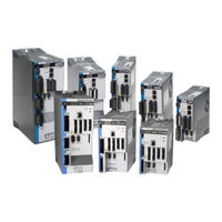
Kollmorgen AKD series Installation Manual (216 pages)
Brand:
Kollmorgen
| Category:
Servo Drives
| Size: 17 MB
Table of Contents
1 Table of Contents
3
2 General
9
About this Installation Manual
10
Using the PDF Format
10
Symbols Used
11
Abbreviations Used
12
Referred Standards
13
3 Safety
14
You Should Pay Attention to this
15
Use as Directed
17
Prohibited Use
18
Warning Notes Placed on the Product
18
4 Handling
19
Transport
20
Packaging
20
Storage
20
Decommissioning
21
Maintenance and Cleaning
21
Disassemble
21
System Repair
22
Disposal
22
5 Approvals
23
Conformance with Ul/Cul
24
UL Markings / Marquages UL
24
Conformance with CE
26
European Directives and Standards for the Machine Builder
27
Conformance with Rohs
27
Conformance with REACH
27
Safe Torque off (STO) Approval
28
Conformance with EAC
28
6 Package
29
Package Supplied
30
Nameplate
30
Part Number Scheme
31
7 Technical Description and Data
32
The AKD Family of Digital Drives
33
Ambient Conditions, Ventilation, and Mounting Position
35
Mechanical Data
35
Inputs/Outputs
36
Electrical Data AKD-Xzzz06
37
Electrical Data AKD-Xzzz07
38
Performance Data
39
Recommended Tightening Torques
39
Grounding System
39
Fusing
40
External Power Supply Fusing
40
External 24 V Supply Fusing
40
External Regen Resistor Fusing
40
External DC Bus Link Fusing
40
Connectors
41
Cable and Wire Requirements
42
General
42
Cable Cross Sections and Requirements
42
Dynamic Braking
43
Regen Circuit
43
Functional Description
43
Technical Data for AKD-Xzzz06
44
Technical Data for AKD-Xzzz07
45
Switch-On and Switch-Off Behavior
46
Switch-On Behavior in Standard Operation
47
Switch-Off Behavior
48
Switch-Off Behavior Using the DRV.DIS Command
48
Switch-Off Behavior Using a Digital Input (Controlled Stop)
49
Switch-Off Behavior Using HW Enable Input (Uncontrolled Stop)
49
Switch-Off Behavior in the Event of a Fault
50
Stop / Emergency Stop / Emergency off
53
Stop
53
Emergency Stop
54
Emergency off
54
Safe Torque off (STO)
55
Safety Characteristic Data
55
Safety Instructions
56
Use as Directed
57
Prohibited Use
57
Technical Data and Pinout
57
Enclosure, Wiring
59
OSSD Test Pulses
59
Functional Description
60
Signal Diagram (Sequence)
61
Wiring Examples
62
Functional Test
64
Shock-Hazard Protection
66
Leakage Current
66
Residual Current Protective Device (RCD)
66
Isolating Transformers
66
8 Mechanical Installation
67
Important Notes
68
Guide to Mechanical Installation
68
Mechanical Drawings Standard Width
69
Control Cabinet Layout AKD-Xzzz06, Standard Width
69
Control Cabinet Layout AKD-Xzzz07, Standard Width
70
Dimensions AKD-Xzzz06, Standard Width
71
Dimensions AKD-Xzzz07, Standard Width
72
Mechanical Drawings Extended Width
73
Control Cabinet Layout, Example with AKD-M00306
73
Control Cabinet Layout, Example with AKD-M00307
74
Dimensions AKD-Xzzz06, Extended Width
75
Dimensions AKD-Xzzz07, Extended Width
76
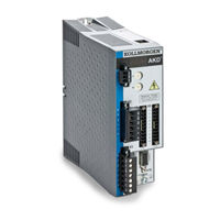
Kollmorgen AKD series Installation Manual (196 pages)
Brand:
Kollmorgen
| Category:
DC Drives
| Size: 11 MB
Table of Contents
Table of Contents
3
Digital Inputs 3 to
7
2 General
9
2 General
10
1 Table of Contents
10
About this Manual
10
Using the PDF Format
10
Notes for the Printed Edition (Paper Version)
10
Symbols Used
11
Abbreviations Used
12
Standards Used
13
3 Safety
14
You Should Pay Attention to this
15
Use as Directed
17
Prohibited Use
17
Handling
18
Packaging
18
Storage
18
Transport
18
Maintenance and Cleaning
19
Repair and Disposal
19
Uninstalling
19
4 Approvals
20
Conformance with Ul/Cul
21
UL Markings
21
CE Conformance
22
European Directives and Standards for the Machine Builder
23
EC Declaration of Conformity
24
Safe Torque off (STO)
25
5 Package
26
Package Supplied
27
Nameplate
27
Part Number Scheme
28
6 Technical Description and Data
29
The AKD Family of Digital Drives
30
Ambient Conditions, Ventilation, and Mounting Position
32
Mechanical Data
32
Inputs/Outputs
33
Electrical Data AKD-Xzzz06
34
Electrical Data AKD-Xzzz07
35
Performance Data
36
Recommended Tightening Torques
36
Fusing
37
External Power Supply Fusing
37
External 24 V Supply Fusing
37
External Regen Resistor Fusing
37
Grounding System
37
Connectors
38
Cable and Wire Requirements
39
General
39
Cable Cross Sections and Requirements
39
Dynamic Braking
40
Regen Circuit
40
Functional Description
40
Technical Data for AKD-Xzzz06
41
Technical Data for AKD-Xzzz07
42
Switch-On and Switch-Off Behavior
43
Switch-On Behavior in Standard Operation
44
Switch-Off Behavior
45
Switch-Off Behavior Using the DRV.DIS Command
45
Switch-Off Behavior Using a Digital Input (Controlled Stop)
46
Switch-Off Behavior Using HW Enable Input (Uncontrolled Stop)
46
Switch-Off Behavior in the Event of a Fault
47
Stop / Emergency Stop / Emergency off
50
Stop
50
Emergency Stop
51
Emergency off
51
Safe Torque off (STO)
52
Safety Characteristic Data
52
Use as Directed
52
Prohibited Use
52
Safety Instructions
53
Technical Data and Pinning
54
Enclosure, Wiring
54
Functional Description
54
Functional Test
55
Signal Diagram (Sequence)
55
Control Circuit (Example)
56
Mains Supply Circuit (Example)
57
Shock-Hazard Protection
58
Leakage Current
58
Residual Current Protective Device (RCD)
58
Isolating Transformers
58
7 Mechanical Installation
59
Important Notes
60
Guide to Mechanical Installation
60
Mechanical Drawings Standard Width
61
Control Cabinet Layout AKD-Xzzz06, Standard Width
61
Control Cabinet Layout AKD-Xzzz07, Standard Width
62
Dimensions AKD-Xzzz06, Standard Width
63
Dimensions AKD-Xzzz07, Standard Width
64
Mechanical Drawings Extended Width
65
Control Cabinet Layout, Example with AKD-M00306
65
Control Cabinet Layout, Example with AKD-M00307
66
Kollmorgen™ | May
66
Dimensions AKD-Xzzz06, Extended Width
67
Dimensions AKD-Xzzz07, Extended Width
68
Advertisement
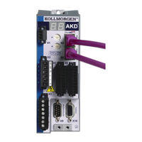
Kollmorgen AKD series Installation Manual (180 pages)
Brand:
Kollmorgen
| Category:
Servo Drives
| Size: 8 MB
Table of Contents
Digital Inputs 1 and
2
Table of Contents
3
1 General
9
About this Manual
10
Target Group
10
Using the PDF Format
10
Abbreviations Used
11
Incremental Encoder (Wake&Shake) X10
11
Symbols Used
12
Standards Used
13
2 Safety
14
Safety Instructions
15
Use as Directed
16
Prohibited Use
16
3 Approvals
17
Conformance with Ul/Cul
18
UL Markings
18
CE Conformance
20
Sine Encoder + Hall => P. 106 X10
20
European Directives and Standards for the Machine Builder
21
EC Declaration of Conformity
22
Safe Torque off (STO)
23
4 Handling
24
Transport
25
Packaging
25
Storage
25
Maintenance and Cleaning
26
Uninstalling
26
Repair and Disposal
26
5 Package
27
Package Supplied
28
Nameplate
28
Part Number Scheme
29
6 Technical Description and Data
30
103 X10
30
The AKD Family of Digital Drives
31
104 X10
31
Ambient Conditions, Ventilation, and Mounting Position
33
Mechanical Data
33
Inputs/Outputs
33
Sincos Encoder Hiperface => P. 105 X10
33
Electrical Data AKD-Xzzz06
34
Electrical Data AKD-Xzzz07
35
Performance Data
36
Recommended Tightening Torques
36
Fusing
37
External Power Supply Fusing
37
External 24 V Supply Fusing
37
External Regen Resistor Fusing
37
Grounding System
37
Connectors
38
AKD-Xzzz06 Types (120V to 240V Mains Voltage Supply)
38
AKD-Xzzz07 Types (240V to 480V Mains Voltage Supply)
38
Cable and Wire Requirements
39
General
39
Cable Cross Sections and Requirements
39
Dynamic Braking
40
Regen Circuit
40
Functional Description
40
Technical Data for AKD-Xzzz06
41
Technical Data for AKD-Xzzz07
42
Switch-On and Switch-Off Behavior
43
Switch-On Behavior in Standard Operation
44
Switch-Off Behavior
45
Switch-Off Behavior Using the DRV.DIS Command
45
Switch-Off Behavior Using a Digital Input (Controlled Stop)
46
Switch-Off Behavior Using HW Enable Input (Uncontrolled Stop)
46
Switch-Off Behavior in the Event of a Fault
47
Stop / Emergency Stop / Emergency off
50
Stop
50
Emergency Stop
51
Emergency off
51
Safe Torque off (STO)
52
Safety Characteristic Data
52
Use as Directed
52
Prohibited Use
52
Safety Instructions
53
Technical Data and Pinning
53
Enclosure
53
Wiring
53
Functional Description
54
Signal Diagram (Sequence)
54
Control Circuit (Example)
55
Functional Test
56
Mains Supply Circuit (Example)
56
Shock-Hazard Protection
57
Leakage Current
57
Residual Current Protective Device (RCD)
57
Isolating Transformers
57
7 Mechanical Installation
58
Safety Instructions
59
Guide to Mechanical Installation
59
Mechanical Drawings Standard Width
60
Control Cabinet Layout AKD-Xzzz06, Standard Width
60
Control Cabinet Layout AKD-Xzzz07, Standard Width
61
Dimensions AKD-Xzzz06, Standard Width
62
Dimensions AKD-Xzzz07, Standard Width
63
Kollmorgen™ | March
63
Mechanical Drawings Extended Width
64
Control Cabinet Layout, Example with AKD-M00306
64
Control Cabinet Layout, Example with AKD-M00307
65
Dimensions AKD-Xzzz06, Extended Width
66
Dimensions AKD-Xzzz07, Extended Width
67
Kollmorgen AKD series Manual (59 pages)
EtherNet/IP Communication
Brand:
Kollmorgen
| Category:
Amplifier
| Size: 0 MB
Table of Contents
Status Word
2
1 Table of Contents
3
2 About this Manual
5
3 Overview
6
4 AKD Ethernet/Ip Features
7
Supported Features
7
Expected Packet Rate
7
Connection Port
7
Network Topology
7
5 Setup
8
Setting an IP Address in the Drive
8
Controller Setup
8
Setting Expected Packet Rate in the Controller
8
6 Communication Profile
9
Explicit Messaging (On-Demand)
9
Supported Services
9
Supported Objects
9
Data Types
10
Error Codes
10
I/O Assembly Messaging (Cyclic)
10
Controller Configuration
10
Command Assemblies
11
Command Assembly Data Structure
11
Control Word
12
Command Type 0X05 - Torque
12
Command Type 0X06 - Position Move
12
Command Type 0X07 - Jog Move
13
Command Type 0X1B - Set Attribute of Position Controller Object
13
Command Type 0X1F - Read or Write Parameter Value
13
Get Attribute
13
Response Assemblies
14
Response Assemly Data Structure
14
Status Word
14
Response Type 0X05 - Actual Torque
15
Response Type 0X14 - Command/Response Error
15
Data Handshake
16
Velocity Mode
17
Setup Velocity Mode
17
Velocity Moves
17
Position Mode
17
Setup Position Mode
17
Homing
18
Position Moves (Point to Point)
18
Running a Stored Motion Task Sequence
18
Torque
18
Setup Torque Mode
18
Torque Moves
19
Handling Faults
19
Saving to Non-Volatile Memory
19
Kollmorgen AKD series Manual (42 pages)
EtherCAT Communication
Brand:
Kollmorgen
| Category:
Servo Drives
| Size: 2 MB
Table of Contents
Table of Contents
3
1 General
5
About this Manual
6
Target Group
6
Warning Symbols
7
Abbreviations Used
8
2 Safety
9
Safety Instructions
10
Use as Directed
11
Prohibited Use
11
3 Installation and Setup
12
Safety Instructions
13
Ethercat Onboard
14
LED Functions
14
Connection Technology
14
Network Connection Example
14
Guide to Setup
15
Setup Via Twincat NC/PTP System Manager
15
Scan Devices
15
Select the Device
17
Scan for Boxes
17
Add Slaves to NC Tasks
18
Enable the Network Configuration
19
Enable the Axis and Move the Axis
20
4 Ethercat Profile
21
Slave Register
22
AL Event (Interrupt Event) and Interrupt Enable
23
Interrupt Enable Register (Address 0X0204:0X0205)
23
AL Event Request (Address 0X0220:0X0221)
24
Phase Run-Up
25
AL Control (Address 0X0120:0X0121)
25
AL Status (Address 0X0130:0X0131)
25
AL Status Code (Address 0X0134:0X0135)
26
Ethercat Communication Phases
26
Canopen over Ethercat (Coe) Status Machine
27
Status Description
27
Commands in the Control Word
28
Status Machine Bits (Status Word)
29
Fixed PDO Mappings
30
Supported Cyclical Setpoint- and Actual Values
30
Supported Operation Modes
30
Adjusting Ethercat Cycle Time
31
Maximum Cycle Times Depending on Operation Mode
31
Synchronization
31
Latch Control Word and Latch Status Word
32
Mailbox Handling
33
Mailbox Output
34
Mailbox Input
35
Example: Mailbox Access
36
Fieldbus Parameters
37
5 Index
39
Kollmorgen | December
40
Kollmorgen AKD series Training Manual (35 pages)
Positioner
Brand:
Kollmorgen
| Category:
Servo Drives
| Size: 2 MB
Table of Contents
Table of Contents
2
Introduction to AKD™ Advanced Kollmorgen Drive
4
Features of AKD
4
Benefits of AKD
4
Wiring the Drive for Training
6
Power Connections
6
Digital Inputs and Outputs
7
Overview
8
Connect to the AKD Drive
8
IP Address
8
Workbench Help
10
Drive Setup Screens
10
Opmode/Source/Enabled/Running
11
Drv.opmode
11
Drv.cmdsource
11
Units
13
Terminal
14
Watch Window
14
Scope Tool
15
Service Motion
15
Motion Task
16
Servo Gains
16
Save & Print
16
Measure
16
Cursor
17
Display
17
Settings
18
AKD™ Motion Task
19
Homing
19
Home Mode Types
19
Home Type 0
19
Home Types 1, 2 & 3
20
Home Types 4, 5 & 6
20
Home Types 7 & 11
21
Home Types 8, 9 & 10
21
Home Type 12
22
Motion Task
22
Absolute Move
22
Relative Move
22
Motion Task
23
Electronic Gearing
26
Leader
26
Follower
27
Tuning
28
Introduction
28
Slider Tuning
29
Bandwidth
29
Slider Tuner - How It Works
30
Limitations of Slider Tuner
31
Appendix A - under Construction
33
Under Construction
35
Appendix B - under Construction
35
Advertisement
Related Products
Kollmorgen AKD-CC
Kollmorgen AKD PDMM series
Kollmorgen AKD-N series
Kollmorgen AKD-N00307
Kollmorgen AKD-N00607
Kollmorgen AKD EtherCAT
Kollmorgen AKD PROFINET RT Communication
Kollmorgen AKD-P01206-NBEC-0000
Kollmorgen AKD 2G
Kollmorgen AKD-x04807
Kollmorgen Categories
Servo Drives
Amplifier
Touch terminals
Engine
DC Drives
More Kollmorgen Manuals
Login
Sign In
OR
Sign in with Facebook
Sign in with Google
Upload manual
Upload from disk
Upload from URL