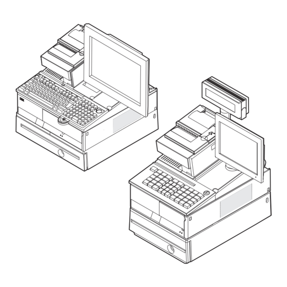
Sign In
Upload
Manuals
Brands
IBM Manuals
Cash Register
4800-741
IBM 4800-741 Manuals
Manuals and User Guides for IBM 4800-741. We have
2
IBM 4800-741 manuals available for free PDF download: Planning, Installation, And Operation Manual, Hardware Service Manual
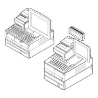
IBM 4800-741 Planning, Installation, And Operation Manual (164 pages)
SurePOS 700 Series
Brand:
IBM
| Category:
Cash Register
| Size: 6.49 MB
Table of Contents
5
Table of Contents
9
Figures
13
Tables
15
About This Guide
15
Who Should Read This Guide
15
How This Guide Is Organized
15
Related Publications
15
Preface
16
Publications Accessibility
16
Sure POS Models 7X1 and 7X2 Important Driver Information
16
Uninterruptible Power Supply Option
17
Ga27-4238-02
17
Ga27-4328-01
17
Summary of Changes
17
Web-Only Update March, 2007
19
Providing Feedback
21
Chapter 1. Introducing the Surepos 700 Models
21
Example of the Wide and Narrow Surepos 700 Series
22
Physical Characteristics
22
Dimensions
22
Controls and Indicators
22
Models and Descriptions
23
Front Panel Controls and Indicators
24
Connectors
24
Overview of Rear Panel
25
Rear View of Input/Output Available On All Models
26
Usb-Only Configuration (Models 7X1)
26
Usb-Only Configuration (Models 7X2)
27
And USB Configuration
28
Cooling
28
Environmental and Temperature
29
Power
29
Power Switch Operation
29
Port DC Loads
30
Uninterruptible Power Supply (Optional)
31
Location of UPS Configuration Switches
32
Power Management
32
UPS Rear View
33
Features and Options
35
Video Function
35
Local Area Network
35
Audio and Headphones
36
Pc I/O
36
System Memory
36
Optional USB DASD
36
USB Support
37
Unique Software Interface
37
I/O Devices
38
Cash Drawers
38
Setting the Cash Drawer Using the Jumper Override
39
Voltage Setting for the 4689 DBCS Surepos Receipt Journal Printer
39
Location of Printer Jumper On the I/O Card
40
Powered USB Connectors
40
Example of the Powered USB Port
41
System and Driver Support
41
Operating Systems
41
Drivers
41
Bios
42
Compatibility
42
Hardware
42
Software
43
Calling for Service
43
Serial Number and Machine Information
45
Chapter 2. Installation and System Setup
45
Before You Begin
45
Supported Operating Systems
45
Determining Your Configuration
45
Your Order and Packaging
46
Setup Procedures
46
Step 1. Installing Your Internal Options
47
Step 2. Wide Units Only: Installing the Expansion Housing and the Optional UPS
47
Removing the Retainer Bracket
48
Correct Placement of System Unit for Installing Expansion Housing
49
Aligning the Expansion Housing with the System Unit
50
Removing the Sheet Metal Panel
50
Connecting the Battery to the UPS
51
Saving the Battery Date Label
51
Inserting the UPS
52
Replacing the UPS Retainer Bracket
53
Step 3. Installing the Cover Kit
53
Installing the Covers
54
View of Rear Door Lower Tabs
54
Installing the Rear Door
55
Removing the CD-ROM Blank
56
Removing the Blank for the UPS Switch Panel
57
Placement of Bezel
58
Step 4. Installing the Slanted I/O Tray (Wide Units Only)
58
Installing Two Mounting Tabs Into the Slanted I/O Tray
59
Step 5. Routing the Cables
59
Step 6. Attaching Your I/O Devices
59
Routing the Cables Through the Slanted I/O Tray
60
Step 7. Installing the Fillers On a Slanted I/O Tray
60
Mounting Locations for the Fillers
61
Installing the Display Filler
61
Installing the Keyboard Filler
62
Installing the Keyboard-Replacement Filler
62
Location of Installed Fillers
63
Step 8. Connecting the Power
64
Step 9. Running the BIOS Configuration Utility
65
Chapter 3. Installing Internal Options
65
Cover Removal Procedures
66
Removing the Front Bezel
67
Opening the Hinged Rear Door
68
Removing the Top Cover
69
Top Plate Removal
69
Top Plate Screws
70
Installing a Feature Card
70
Installing Feature Cards
71
Installing Memory Modules
71
Replacing the Memory Modules
73
Chapter 4. Installing External Options
73
Before You Start
73
To Install the Surepos 700
73
Attaching the Cables to the System Unit
73
Securing IBM USB POS Keyboard Cables
74
Securing the Cable Using Cable Ties
74
Pictorial Steps to Attach the Cable with Clips and Brackets
75
Installing the Cash Drawer and the System Unit
75
Securing the Cable with Cable Ties
76
Place the System Unit On the Cash Drawer
77
Non-Ibm Cash Drawers: Setting the Jumper for the Correct Voltage
77
Removing and Replacing the Cash Drawer Coin-Roll Cutter (Compact Cash Drawer Only)
78
Install Coin-Roll Cutter
79
Installing I/O Trays
79
Installing an I/O Tray On the System Unit
79
Installing the Slanted I/O Tray
80
Installing a Slanted I/O Tray On the Full-Size Cash Drawer
80
Installing the Fillers
80
Installing the Tape-Holder Kit
80
Installing Two Mounting Tabs Into the Slanted I/O Tray
81
Removing the Tape-Holder Latch
81
Snapping the Tape-Holder Into Place
82
Installing the Printer
82
Install the Printer
83
Installing the 40-Character LCD
83
Assemble the Post
83
Slide Display Into Holder
84
Plug Cable Into Display Unit
84
Assembling the Display
85
Attachment Points for the Display Post
86
Installing the 40-Character VFD
86
Assemble the Post
86
Routing the Cable
87
Placement of the Display On the Arm
88
Installing the Character/Graphics Display
88
Installing the Display Post with a Snap
88
Connecting the Character/Graphics Display Post
89
Routing the Character/Graphics Display Cable
89
Installing the Character/Graphics Display
90
Placing the Post Into the Filler Hole
91
Installing the Display Post with a Base
91
Connecting the Character/Graphics Display Post
92
Placement of the Character/Graphics Display On the Arm
92
Routing the Cable
93
Installing the Guidance Label
94
Attaching an IBM Surepoint Solution
94
IBM Surepoint Solution Display
95
Installing CRT Displays
95
Installing a CRT On a Wedge Mount
95
Installing the Power Cord and Video Cable On a CRT Wedge Mount
96
Installing a CRT in a Slanted I/O Tray
97
Installing a CRT On a Post Mount
98
Attaching the Distributed Pedestal to the Counter
98
Pedestal Mounting Diagram
99
Pedestal Mounting Template
100
Attaching the Pedestal to the Short-Post Mounting Plate
100
Attaching the Short Post Mounting Plate to the Pedestal
100
Attaching the Three Extra Feet to the Cash Drawer
101
Installing the Large CRT Table Post Mount to a Pedestal
101
Attaching the Short CRT Post Mount to the Large CRT Table Post Mount
102
Installing and Removing Lock Inserts
102
Preparing to Install a Lock or a Blank Lock Insert
102
Installing a Lock Insert
102
Lock Inserts and Accessories
102
Aligner Positions
103
Removing a Lock Insert
103
Install a Lock Insert
104
Installing a Blank Lock Insert
104
Remove a Lock Insert
104
Align the Lug with the Slot in the Lock Cylinder
105
Removing a Blank Lock Insert
105
Installing the Keyboard-V and the PLU Keyboard
105
Changing the Keytop Labels
105
Installing the Keytop Labels
106
Installing a Vertical Stand
106
Placing the System Unit On the Vertical Stand
107
Wide Models Only: Installing the Front Service Housing
107
Removing the Bottom Feet
107
Attaching the System and Bezel Latches
107
Attaching the Rear Latch
108
Attaching the Bezel Latch
109
Attaching the Pull-Out Handle
109
Installing the Cable Guide and the Cable Guide Arm Assembly
110
Attaching the Cable Guide
110
Positioning the Cable Guide Arm Assembly
111
Attaching the Cable Guide Arm Assembly
112
Inserting the System Unit Into the Service Housing
112
Attaching the I/O Tray
112
Inserting the Unit Into the Service Housing
113
Routing the Cables
113
Installing the I/O Tray
114
Extra Cord Length During Routing
115
Cable Assembly Arm with Cables Securely in Place
116
Cable Guide Arm Assembly Latch
117
Installing the Display Stand
117
Attaching the Back Cover
118
Installing the Printer
118
Routing the Cable Through the Pedestal
119
Chapter 5. Diagnostics and Configuration Settings
119
Service and Diagnostics
119
Using the BIOS Setup Program
119
Navigation and Menus
120
Saving Settings
120
Boot Device Order
120
Restoring CMOS Default Settings
123
Chapter 6. Operating POS I/O Devices
123
Displays
124
Adjusting the Controls On Video Displays
124
Cash Drawers
124
CRT Displays
124
Controls On 9-In. Monochrome Display
124
Full-Size Cash Drawer
125
Lock Positions
125
Document Storage Area Under Cash Drawer
125
Compact Cash Drawer
126
Cash-Drawer Options
126
Compact Cash-Drawer Only: Using the Cash-Drawer Coin-Roll Cutter
126
Cash-Drawer Depth-Adjustment Bar
127
Using the Coin-Roll Cutter
128
Keyboards
128
Manager's Lock
128
Keyboard Types for the Surepos 700
129
Function Keys
129
Keyboard Lights (Status Indicators)
129
Example of S1 and S2 Function Keys
130
Using the USB Keyboard-V
130
Location of Keyboard Status-Indicator Lights
130
Location of Keyboard-V Status Indicators
130
Keyboard Status-Indicator Lights Meanings
131
USB Keyboard-V Volume Control
132
Location of Mode Lock Keys
132
Location of System Function Keys
133
Using the USB PLU Keyboard/Display
133
Status Indicators
133
USB PLU Keyboard/Display Status-Indicators Meanings
134
Settings for DIP Switches SW3 and SW4
134
Location of Plu-Keyboard DIP Switches
134
Location of Volume Control On USB PLU Keyboard/Display
135
Entering Data at Your Terminal
135
Operating Card Readers
135
Cleaning the Card Reader
135
Location of System Function Keys
136
Printers
137
Chapter 7. Testing
137
Preliminary Checklist
138
Problem Isolation
139
Appendix A. Safety Information
145
Appendix B. Notices
147
Electronic Emission Notices
147
Federal Communications Commission (FCC) Statement
147
European Union EMC Directive Conformance Statement
148
Industry Canada Class a Emission Compliance Statement
148
Avis De Conformité Aux Normes D'industrie Canada
148
Germany
148
Australia and New Zealand
149
Chinese Class a Warning Statement
149
Japanese Power Line Harmonics Compliance Statement
149
Japanese Voluntary Control Council for Interference (VCCI) Statement
149
Korean Communications Statement
150
Taiwanese Class a Warning Statement
150
Taiwan Contact Information
150
Cable Ferrite Requirement
150
Electrostatic Discharge (ESD)
151
Product Recycling and Disposal
152
Battery Return Program
152
For Taiwan
152
For the European Union
153
For California
153
Flat Panel Displays
153
Monitors
153
Trademarks
155
Appendix C. Intel Software License Agreement (Final, Single User)
155
Important - Read before Copying, Installing or Using
155
Copyright License
155
Ownership of Software and Copyrights
155
Limited Media Warranty
155
Exclusion of Other Warranties
156
Limitation of Liability
156
Termination of This Agreement
156
Applicable Laws
156
Government Restricted Rights
157
Index
Advertisement
IBM 4800-741 Hardware Service Manual (144 pages)
SurePOS 700 Series
Brand:
IBM
| Category:
Cash Register
| Size: 12.8 MB
Table of Contents
5
Table of Contents
9
Figures
13
About This Guide
13
Who Should Use This Guide
13
How This Guide Is Organized
13
Related Publications
13
Preface
14
Publications Accessibility
14
Sure POS Models 7X1 and 7X2 Important Driver Information
15
August, 2006
15
July 2008
15
March, 2006
15
March, 2007
15
October, 2007
15
Summary of Changes
17
Providing Feedback
19
Chapter 1. Introducing the Surepos 700 Models
19
Example of the Wide and Narrow Surepos 700 Series
20
Physical Characteristics
20
Dimensions
20
Controls and Indicators
20
Models and Descriptions
22
Connectors
23
Rear Icons and Definitions
24
Usb-Only Configuration (Models 7X1)
24
Usb-Only Configuration (Models 7X2)
25
And USB Configuration
26
Cooling
26
Environmental and Temperature
27
Power
27
Power Switch Operation
27
Port DC Loads
28
Uninterruptible Power Supply (Optional)
28
Battery Life
28
Input Voltage
29
Location of UPS Configuration Switches
30
Power Management
30
UPS Rear View
31
Features and Options
33
Video Function
33
Local Area Network
33
Audio and Headphones
34
Pc I/O
34
System Memory
34
Optional USB DASD
34
USB Support
35
Unique Software Interface
35
I/O Devices
36
Cash Drawers
36
Cash Drawer Jumper Settings
37
Voltage Setting for the 4689 DBCS Surepos Receipt Journal Printer
37
Location of Printer Jumper On the I/O Card
38
Powered USB Connectors
39
System and Driver Support
39
Operating Systems
39
Drivers
39
Bios
40
Compatibility
40
Hardware
40
Software
41
Calling for Service
43
Chapter 2. Removal and Replacement Procedures
43
Removing the Memory Modules Removing the Front Service Housing Components (Wide Models Only)
44
Before You Begin
44
Cables, Connectors, and Headphones
44
Processor Power Cable
45
Connecting Your Cash Drawer to Surepos Models 721, 741, and 781
46
Removing the Slanted I/O Trays
46
Removing the Slanted I/O Tray
47
Removing the Covers
47
Removing the Front Bezel
50
Removing the Top Plate
51
Removing the CD-ROM
52
Removing the CD-ROM
54
Removing the Hard Disk Drive
56
Removing the Exhaust Fan (Models 742 and 782 Only)
57
Replacing the Insulating Rubber Seal (Models 722, 742, and 782 Only)
57
Location of Alignment Pen Holes
59
Removing the Spline
60
Removing the I/O Modules
60
Opened I/O Latch
61
Removing the I/O Module Holders
62
Removing the Air Duct (Models 722, 74X, 78X, and C4X)
62
Removing the Air Duct
63
Removing the Processor Fan (Models 742, 782 Only)
63
Removing the Heat Sink and Processor
65
Removing the Control Switch Card
66
Removing the Power Supply
67
Removing the Riser Card
70
Dump Switch
72
Removing the Planar
73
Planar Location
74
Removing the UPS
74
Lifting the Bracket
75
Removing the UPS
76
Removing the Expansion Housing
78
Removing the UPS Battery
79
Removing the Front USB Card
80
Removing the Memory Modules
82
Removing the Front Service Housing Components (Wide Models Only)
82
Removing the System and Bezel Latches
82
Removing the System Latch
84
Removing the Pull-Out Handle
84
Removing the Cable Guide
85
Removing the Cable Guide Arm Assembly
85
Removing the Cable Guide
86
Positioning the Cable Guide Arm Assembly
87
Routing the Cables
91
Chapter 3. Problem Determination
91
Preliminary Checklist
92
Problem Isolation
92
Actions to Isolate the Cause of a Problem
93
Special Tools Requirements
93
Using the RAID Application
93
Determining a Hard Drive Failure
95
Replacing and Rebuilding a Hard Drive
95
Accessing the RAID Setup Menu
95
Boot Up Warning
96
Example of the RAID Setup Menu
97
Chapter 4. Diagnostics and Configuration Settings
97
Service and Diagnostics
97
Using the BIOS Setup Program
97
Navigation and Menus
98
Saving Settings
98
Boot Device Order
98
Restoring CMOS Default Settings
99
CMOS Jumper and Pin Location By Model
101
Appendix A. Parts Catalog
102
Assembly 1: Models 721, 741 and 781
106
Assembly 2: Models 722, 742, and 782
110
Assembly 3: Slanted I/O Tray
112
Assembly 4: Front Service Assembly
114
Line Cord Assemblies
114
Power Cords for All Models
115
Appendix B. Safety Information
121
Appendix C. Notices
123
Electronic Emission Notices
123
Federal Communications Commission (FCC) Statement
123
European Union EMC Directive Conformance Statement
124
Industry Canada Class a Emission Compliance Statement
124
Avis De Conformité Aux Normes D'industrie Canada
124
Germany
124
Australia and New Zealand
125
Chinese Class a Warning Statement
125
Japanese Power Line Harmonics Compliance Statement
125
Japanese Voluntary Control Council for Interference (VCCI) Statement
125
Korean Communications Statement
126
Taiwanese Class a Warning Statement
126
Taiwan Contact Information
126
Cable Ferrite Requirement
126
Electrostatic Discharge (ESD)
127
Product Recycling and Disposal
128
Battery Return Program
128
For Taiwan
129
For the European Union
129
For California
130
Flat Panel Displays
130
Monitors and Workstations
130
Trademarks
131
Appendix D. Intel Software License Agreement (Final, Single User)
131
Important - Read before Copying, Installing or Using
131
Copyright License
131
Ownership of Software and Copyrights
131
Limited Media Warranty
131
Exclusion of Other Warranties
132
Limitation of Liability
132
Termination of This Agreement
132
Applicable Laws
132
Government Restricted Rights
133
Index
137
Part Number Index
Share and save
Advertisement
Related Products
IBM 4800-C41
IBM 4951-514
IBM 4840-563
IBM 4694-207
IBM 4694-247
IBM 4694-307
IBM 4694-347
IBM AnyPlace 4836
IBM AnyPlace 4838
IBM 4807
IBM Categories
Server
Desktop
Storage
Laptop
Monitor
More IBM Manuals
×
Login
Sign In
OR
Sign in with Facebook
Sign in with Google
×
Upload manual
Upload from disk
Upload from URL