Sign In
Upload
Manuals
Brands
FreeFlight Manuals
Receiver
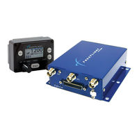
ADS-B FDL-978-XVRL
FreeFlight ADS-B FDL-978-XVRL Manuals
Manuals and User Guides for FreeFlight ADS-B FDL-978-XVRL. We have
2
FreeFlight ADS-B FDL-978-XVRL manuals available for free PDF download: Installation Manual
FreeFlight ADS-B FDL-978-XVRL Installation Manual (182 pages)
Brand:
FreeFlight
| Category:
Receiver
| Size: 9 MB
Table of Contents
Table of Contents
5
General Information
17
Introduction
17
Acronyms and Abbreviations
18
Alert Symbol Usage
20
General System Description
21
Fdl-978-Rx Block
24
Figure 4. Fdl-978 Series
24
Tc978 Controller
26
Uat Antenna Requirements
27
Gps Antenna Requirements
27
Technical Characteristics
28
Series
28
Tc978 Controller
29
Parts and Equipment
30
Series Items
30
Series Installation Kits
30
Materials Required but Not Supplied
33
List of Other Approved Gps Antennas
33
Ft-9000 Ramp Tester
34
Series Installation
36
Unpacking and Inspecting Equipment
36
Equipment Mounting
36
Series
37
Figure 6. Fdl-978 Seriesm
37
Tc978 Controller
38
Cooling Requirements
38
Electrical Connections
39
Interface - Db-44 Pinout
39
Interface Details
40
Power Input
40
Personality Module
41
Status Leds
41
Remote Power Control
42
Tc978 Controller Interface
42
Configurable Serial Interfaces
42
ARINC 429 Ports
44
Discrete Inputs
44
Air/Ground Input
45
Anonymous Mode Input
45
Traffic Test Input
45
Discrete Output
46
TX Suppression Output
46
UAT Status Output
46
Time Mark Input/Output
46
Maintenance Port Interface
47
Figure 8. Inline Mpi Connector and Figure 9. Personality Module
47
Tc978 Controller Electrical Connections
48
Tc978 Interface - Db-9 Pinout
48
Tc978 Controller Interface Details
48
Power
48
Mpi Pinout
48
Remote on
49
Tmap Bus
49
Altitude out
49
Tc978 Connections
49
Personality Module Installation
50
Wiring Considerations
52
Uat Antenna Installation
52
Uat Antenna Ground Plane
53
Uat Antenna Cable
53
Gps Antenna Installation
54
Antenna Power
55
Recommended Cable
55
Satcom Compatibility
55
Tc978 Static Pressure Connection
55
Equipment Limitations
56
Non-TSO Functions
57
Department of Commerce Compliance
57
Series Configuration and Checkout
59
General
59
Continued Airworthiness Requirements
59
Tc978 Controller Operation
59
Display
60
Fault Annunciation
61
Warning Messages
61
Preliminary Checkout
61
Installation Setup and Configuration
62
Fdl-978-Xvr Configuration Item Summary
63
Table 2. Serial and Arinc P
63
Series Serial and Arinc Port Configuration Details
65
Table 4. Display Outputc
65
Table 5. Fdl-978 Seriesi
65
Serial Port Input Configuration
68
Table 6. Serial Port Inputc
68
Table 7. Serial Port Inputb
69
Serial Port Output Configuration
70
Table 8. Serial Port Output
70
ARINC 429 Port Input Configuration
71
Table 9. Serial Port Output
71
Table 12. Gps-743 Input Arinc L
72
Table 14. Transpnder -Cntrl
73
ARINC 429 Port Output Configuration
74
Table 18.Traffic Format Input
74
Table 21. Traffic Formato
75
Table 22. Gps-743 Outputl
76
Mpi Module Overview
77
Installation Adapter
77
Mpi Module
77
Ads-B Mpi App
77
Figure 12. Installation Adapter
77
Mpi Hardware Configuration
78
Terminal Program Interface
78
Figure 14. Tera Term Terminal
78
Figure 15 . Tera Term Serial
79
MPI Serial Connection Settings
79
Table 23. Default Mpi Portc
79
Table 24. Tera Term W I -Fic
79
Terminal MPI Wi-Fi Connection Settings
79
Figure 16. Tera Term W I -Fic
80
Initial MPI Connection
80
Terminal Maintenance Commands
81
Help or ?" Command
81
Ads" Command
82
Bit" Command
82
Comm" Command
82
Control" Command
83
Gps" Command
83
Info" Command
83
Reset" Command
83
Rxstatus" Command
84
Cnfg" Command
85
Cnfg Defaults" Command
86
Deleted
86
Serial and ARINC Port Settings
87
Set Serial In" Command
87
Set" Command
87
Set Serial Out" Command
88
Set Arinc In" Command
89
Set Arinc Out" Command
89
ADS-B Transmit Settings
90
Set Addr" Command
90
Set Call Sign" Command
90
Set Gps" Command
90
Set Gps "Set Rx" Command
91
Set Nacv" Command
91
Set Emit Cat" Command
92
Set Squat" Command
92
Set Acsize" Command
93
Set Threshold" Command
93
Set Uatant" Command
93
Set Disablesquawktx" Command
94
Set Gpsant" Command
94
Set Modearx" Command
94
Display Output Settings
95
Set Cheltoncsa" Command
95
Set Max Trgs" Command
95
Set Trafvelval" Command
95
Set Displayout
96
Terminal Maintenance Port Interface Security
97
Checkpw" Command
97
Setpw" Command
97
Maint Ascii Pw" Command
98
Resetpw" Command
98
Resetting Forgotten Password
98
Configuration and Setup Using Tc978
99
Entering Configuration Mode
99
Fdl-978-Xvr Configuration Mode Operation
99
Aircraft Mode S (or ICAO) Address
100
VFR Flight ID
100
VFR Squawk Code
100
Groundspeed Threshold
101
Aircraft (Emitter) Category
102
Squat Switch Type
102
Serial in Channel X Data Type
103
Serial in Channel X Line Speed
104
Serial out Channel X Data Type
104
Serial out Channel X Line Speed
105
ARINC in Channel X Data Type
106
ARINC in Channel X Interface Speed
106
ARINC out Chan 1 Data Type
107
ARINC out Chan 1 Interface Speed
107
GPS Certification
108
Select Max Targets Output
108
Aircraft Length
109
Aircraft Width
109
GPS NAC Velocity
109
GPS Reference Position Offset
110
1090 Mhz Receiver Installed
111
Mode A/C Receiver Sets Squawk
111
UAT Receiver Installed
111
UAT Antenna Check Ground
112
UAT Antenna Diversity
112
Tc978 Test and Calibration
113
Local Voltage Supply Test
113
Tc978 Altitude Encoder Calibration
113
Calibration Equipment
113
Calibration Procedure
113
Pressure Altitude Reported
115
Troubleshooting
116
General
116
Fdl-978-Xvr Led Troubleshooting Procedure
116
Uat Status Led/Discrete Fault Indications
117
Warning Messages
118
Tc978 Warning Message Troubleshooting
118
Rtca/Do-160 Environmental Qualifications
121
Equipment and Uat Do-160 Qualification
121
Tc978 Controller Do-160 Qualification
123
Serial Interface Specifications
125
Altitude Encoder Format
125
Air Data Computer/Sensor Format
125
Ads-B Compliance
127
Installation Drawings
129
Dimensions
129
Figure 17. Fdl-978 Series and
129
TC978 Controller Cut-Out Options
130
Typical Interconnect Diagrams
133
Typical System Configurations
133
Garmin Gns 430W/530W Display and Gps, Gtx-330 Transponder
135
Figure 21. Garmin Gns 430W/530W D
135
Table 25. Garmin Systemc
135
Figure 23. Aspen Display and Figure 24. Bendix King
137
Bendix King Ksn 765/770 Display and Gps, Gtx-327 Transponder
138
Table 28. Bendix King
138
Mode A/C Transponder, TC978 Controller
139
Figure 25. Mode A/C Transponder
139
Table 29. Mode A/C Transponder
139
Garmin GNS 480, SL-70 Transponder, TCAS
140
Figure 26. Garmin Gns 480, Sl-70 T
140
Table 30. Garmin Gns 480, Sl-70 T
140
Garmin MX-20 Display and Control, no Transponder
141
Figure 27. Garmin MX-20 D
141
Table 31. Garmin MX-20 D
141
Garmin GMX-200 Display, GTX-330 Transponder
142
Figure 28. Garmin Gmx-200 D
142
Table 32. Garmin Gmx-200 D
142
Equipment Specific Installations
145
Freeflight Systems 1201 GPS
145
Freeflight Systems 1203C Gps
145
Figure 30. 1201 Wiring Diagram
145
Figure 31. 1203C Wiringd
145
Equipment Compatibility and Functions
146
Figure 22. Chelton Flight Logic
146
Table 26. Chelton Flight Logic
146
Table 35. Compatible Software
146
Section 10 Maintenance Interface Diagrams
149
Figure 32. off - the -Shelf
149
Figure 33. Serial - to -W I -F I
150
Figure 34. Serial - to -W I -Fia
151
Section 11 Warning Disclaimer
153
Section 12 Fdl-978 Lite Series
155
General System Description
155
Figure 35. Fdl-978 Lite Series
155
Technical Characteristics
158
Parts and Equipment
159
Lite Series Items
159
Installation
161
Unpacking and Inspecting Equipment
161
Equipment Mounting
161
Cooling Requirements
161
Electrical Connections
162
Interface - Db-44 Pinout
162
Interface Details
163
Power Input
163
Status Leds
163
Remote Power Control
163
Tc978 Controller Interface
163
Control Data Interface
163
Altitude Input Data Interface
164
Discrete Inputs
164
Air/Ground Input
164
Anonymous Mode Input
164
Discrete Output
164
Wi-Fi Module or Maintenance Port Interface
165
Initial MPI Connection
165
Tc978 Controller Electrical Connections
165
Wiring Considerations
165
Uat Antenna Installation
165
Configuration and Checkout
165
Installation Setup and Configuration
166
Lite Series Configuration Item Summary
166
Lite Series Interface Configuration Details
166
Control Data Interface
166
Table 36. Serial Portc
166
Altitude Input Interface
167
Wi-Fi Module or Maintenance Port Interface
167
Configuration and Setup Using Tc978
168
Entering Configuration Mode
168
Configuration Mode Operation
168
Aircraft Mode S (or ICAO) Address
169
VFR Squawk Code
169
Groundspeed Threshold
170
VFR Flight ID
170
Aircraft (Emitter) Category
171
Aircraft Length
172
Aircraft Width
172
GPS Reference Position Offset
172
Serial in Channel 4 Data Type
172
1090 Mhz Receiver Installed
174
UAT Receiver Installed
174
Tc978 Test and Calibration
175
Troubleshooting
175
Rtca/Do-160 Environmental Qualifications
175
Serial Interface Specifications
175
Ads-B Compliance
175
Installation Drawings
175
Typical Interconnect Diagrams
176
Maintenance Interface Diagrams
178
Section 13 Limited Warranty
179
Advertisement
FreeFlight ADS-B FDL-978-XVRL Installation Manual (168 pages)
Brand:
FreeFlight
| Category:
Receiver
| Size: 6 MB
Table of Contents
Table of Contents
5
General Information
15
Introduction
15
Acronyms and Abbreviations
15
Fdl-978-Xvrl
15
Alert Symbol Usage
18
General System Description
18
Fdl-978-Rx Block Diagram (Typical )
21
Figure 4. Fdl-978 Series
21
Tc978 Controller
23
Gps Antenna Requirements
24
Uat Antenna Requirements
24
Technical Characteristics
25
Series
25
Tc978 Controller
26
Parts and Equipment
27
Series Items
27
Series Installation Kits
27
Materials Required but Not Supplied
30
List of Other Approved Gps Antennas
30
Ft-9000 Ramp Tester
30
Series Installation
31
Unpacking and Inspecting Equipment
31
Equipment Mounting
31
Series
32
Tc978 Controller
32
Figure 6. Fdl-978 Series Mounting Dimensions
32
Cooling Requirements
33
Electrical Connections
33
Interface - Db-44 Pinout
33
Interface Details
35
Power Input
35
Personality Module
35
Status Leds
36
Remote Power Control
37
Tc978 Controller Interface
37
Configurable Serial Interfaces
38
ARINC 429 Ports
39
Discrete Inputs
39
Air/Ground Input
40
Anonymous Mode Input
40
Traffic Test Input
40
Discrete Output
41
UAT Status Output
41
Tx Suppression Output
41
Time Mark Input/Output
41
Maintenance Port Interface
42
Tc978 Controller Electrical Connections
43
Tc978 Interface - Db-9 Pinout
43
Tc978 Controller Interface Details
43
Power
43
Remote on
43
Tmap Bus
44
Altitude out
44
Tc978 Connections
44
Personality Module Installation
44
Figure 8. Personality Module Assembly
45
Wiring Considerations
46
Uat Antenna Installation
46
Uat Antenna Ground Plane
47
Uat Antenna Cable
47
Gps Antenna Installation
48
Antenna Power
49
Recommended Cable
49
Satcom Compatibility
49
Tc978 Static Pressure Connection
49
Equipment Limitations
50
Department of Commerce Compliance
51
Series Configuration and Checkout
54
General
54
Continued Airworthiness Requirements
54
Tc978 Controller Operation
54
Display
55
Figure 10. FDL-978 Controller Display (Typical)
55
Mode Selection Knob
55
Push Buttons
57
Code Knob
60
Fault Annunciation
60
Warning Messages
60
Preliminary Checkout
60
Installation Setup and Configuration
61
Fdl-978-Xvr Configuration Item Summary
62
Table 1. Serial and Arinc Port Configuration Settings
62
Table 3. Display Output Configuration Settings
63
Series Serial and Arinc Port Configuration Details
64
Table 4. Fdl-978 Series Installation Data Interfaces
64
Serial Port Input Configuration
67
Table 5. Serial Port Input Configuration Settings
67
Table 6. Serial Port Input Baud Rate Settings
68
Serial Port Output Configuration
69
Table 7. Serial Port Output Configuration Settings
69
ARINC 429 Port Input Configuration
70
Table 8. Serial Port Output Baud Rate Settings
70
Table 11. Gps-743 Input Arinc Labels
71
Table 13. Transpnder-Cntrl Input ARINC Labels
72
ARINC 429 Port Output Configuration
73
Table 17.Traffic Format Input Arinc Labels
73
Table 20. Traffic Format Output Arinc Labels
74
Table 21. Gps-743 Output Labels Order
75
Mpi Module Overview
76
Mpi Module
76
Ads-B Mpi App
76
Mpi Hardware Configuration
76
Top Components
76
Front Component
76
Back Components
77
Figure 14. Db-9 Connector
77
Mpi Back View
77
Terminal Program Interface
78
Initial MPI Connection
78
MPI Serial Connection Settings
78
MPI Wi-Fi Connection Settings
78
Maintenance Commands
78
Help or ?" Command
79
Ads" Command
80
Bit" Command
80
Comm" Command
80
Control" Command
81
Gps" Command
81
Info" Command
81
Reset" Command
81
Rx Status" Command
82
Cnfg" Command
83
Cnfg Defaults" Command
84
Cnfgstatus" Command
84
Set" Command
84
Serial and ARINC Port Settings
85
Set Serial In" Command
85
Set Serial Out" Command
85
Set Arinc In" Command
86
Set Arinc Out" Command
86
ADS-B Transmit Settings
87
Set Addr" Command
87
Set Call Sign" Command
87
Set Gps" Command
87
Set Gps "Set Rx" Command
88
Set Nacv" Command
88
Set Emit Cat" Command
89
Set Squat" Command
89
Set Acsize" Command
90
Set Threshold" Command
90
Set Uatant" Command
90
Set Disablesquawktx" Command
91
Set Gpsant" Command
91
Set Modearx" Command
91
Display Output Settings
92
Set Cheltoncsa" Command
92
Set Max Trgs" Command
92
Set Trafvelval" Command
92
Set Displayout
93
Configuration and Setup Using Tc978
94
Entering Configuration Mode
94
Fdl-978-Xvr Configuration Mode Operation
94
Aircraft Mode S (or ICAO) Address
95
VFR Flight ID
95
VFR Squawk Code
95
Groundspeed Threshold
96
Aircraft (Emitter) Category
97
Squat Switch Type
97
Serial in Channel X Data Type
98
Serial in Channel X Line Speed
99
Serial out Channel X Data Type
99
ARINC in Channel X Data Type
100
Serial out Channel X Line Speed
100
ARINC in Channel X Interface Speed
101
ARINC out Chan 1 Data Type
101
ARINC out Chan 1 Interface Speed
102
Select Max Targets Output
102
GPS Certification
103
GPS NAC Velocity
103
Aircraft Length
104
Aircraft Width
104
GPS Reference Position Offset
105
1090 Mhz Receiver Installed
106
Mode A/C Receiver Sets Squawk
106
UAT Receiver Installed
106
UAT Antenna Check Ground
107
UAT Antenna Diversity
107
Tc978 Test and Calibration
108
Local Voltage Supply Test
108
Tc978 Altitude Encoder Calibration
108
Calibration Equipment
108
Calibration Procedure
108
Pressure Altitude Reported
110
Troubleshooting
111
General
111
Fdl-978-Xvr Led Troubleshooting Procedure
111
Uat Status Led/Discrete Fault Indications
112
Warning Messages
113
Tc978 Warning Message Troubleshooting
113
Rtca/Do-160 Environmental Qualifications
115
Equipment and Uat Do-160 Qualification
115
Tc978 Controller Do-160 Qualification
116
Serial Interface Specifications
117
Altitude Encoder Format
117
Air Data Computer/Sensor Format
117
Ads-B Compliance
119
Installation Drawings
121
Dimensions
121
TC978 Controller Cut-Out Options
122
Tc978 Controller Dimensions
122
Typical Interconnect Diagrams
125
Gps 430W/530W Configuration
127
Xpdr Monitor
128
Fdl-978-Rx Receiver with Internal Gps
134
Section 10 Maintenance Interface Diagrams
135
Section 11 Warning Disclaimer
139
Section 12 Fdl-978 Lite Series
141
General System Description
141
Fdl-978-Txl
142
Technical Characteristics
144
Parts and Equipment
145
Lite Series Items
145
Installation
147
Unpacking and Inspecting Equipment
147
Equipment Mounting
147
Cooling Requirements
147
Electrical Connections
148
Interface - Db-44 Pinout
148
Interface Details
149
Power Input
149
Status Leds
149
Remote Power Control
149
Tc978 Controller Interface
149
Control Data Interface
149
Altitude Input Data Interface
150
Discrete Inputs
150
Air/Ground Input
150
Anonymous Mode Input
150
Discrete Output
150
Wi-Fi Module or Maintenance Port Interface
151
Tc978 Controller Electrical Connections
151
Wiring Considerations
151
Uat Antenna Installation
151
Configuration and Checkout
151
Installation Setup and Configuration
152
Lite Series Configuration Item Summary
152
Lite Series Interface Configuration Details
152
Control Data Interface
152
Table 22. Serial Port Configuration Settings
152
Altitude Input Interface
153
Wi-Fi Module or Maintenance Port Interface
153
Configuration and Setup Using Tc978
154
Entering Configuration Mode
154
Configuration Mode Operation
154
Aircraft Mode S (or ICAO) Address
155
VFR Squawk Code
155
Groundspeed Threshold
156
VFR Flight ID
156
Aircraft (Emitter) Category
157
Aircraft Length
158
Serial in Channel 4 Data Type
158
Squat Switch Type
158
Aircraft Width
159
GPS Reference Position Offset
159
Tc978 Test and Calibration
160
Troubleshooting
160
Rtca/Do-160 Environmental Qualifications
160
Serial Interface Specifications
160
Ads-B Compliance
160
Installation Drawings
160
Typical Interconnect Diagrams
161
Table 24. Typical Transponder Connections
162
Maintenance Interface Diagrams
163
Section 13 Limited Warranty
165
Advertisement
Related Products
FreeFlight ADS-B FDL-978 Series
FreeFlight ADS-B FDL-978-XVR
FreeFlight ADS-B FDL-978-RX
FreeFlight ADS-B FDL-978-TXL
FreeFlight ADS-B FDL-DB Dual Band Series
FreeFlight FWF-125
FreeFlight 87098-00
FreeFlight 87098-00-FR00
FreeFlight 87098-00-FX00
FreeFlight 87098-10
FreeFlight Categories
Receiver
Measuring Instruments
Transceiver
Transmitter
Avionics Display
More FreeFlight Manuals
Login
Sign In
OR
Sign in with Facebook
Sign in with Google
Upload manual
Upload from disk
Upload from URL