FreeFlight ADS-B FDL-978 Series Installation Manual
Hide thumbs
Also See for ADS-B FDL-978 Series:
- Installation manual (168 pages) ,
- Quick reference manual (2 pages) ,
- User manual (26 pages)
Table of Contents
Advertisement
Quick Links
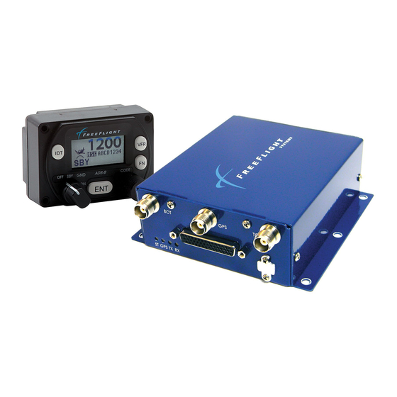
ADS-B FDL-978 Series
and FDL-978 Lite Series
Installation Manual
Part Numbers
P/N 87098-XX-XXXX
Document No. 87343
This document contains FreeFlight Systems proprietary information. It is loaned for limited purposes only and
remains the property of FreeFlight Systems. It may not be reproduced in whole or in part without written consent
of FreeFlight Systems and must not be disclosed to persons not having need of such disclosure consistent with
the purpose of the loan. The document is to be returned to FreeFlight Systems upon request and/or upon
completion of the use for which it was loaned.
Advertisement
Table of Contents
Troubleshooting

Related Manuals for FreeFlight ADS-B FDL-978 Series


Summary of Contents for FreeFlight ADS-B FDL-978 Series
- Page 1 This document contains FreeFlight Systems proprietary information. It is loaned for limited purposes only and remains the property of FreeFlight Systems. It may not be reproduced in whole or in part without written consent of FreeFlight Systems and must not be disclosed to persons not having need of such disclosure consistent with the purpose of the loan.
- Page 3 The information provided in this document is subject to change without notice. Please visit the FreeFlight Systems website (http://www.freeflightsystems.com) or contact Product Support for updated materials regarding your products. For Product Support, Repair, or Sales, please contact us directly or an authorized FreeFlight Systems Dealer. Product Support Department: Phone: +1.254.662.0000, ext.
- Page 4 ADS-B FDL-978 Series and Lite Series Installation Manual Document No. 87343 Rev G History of Revisions Dates of Revision are: Revision .….. A …………… June 13, 2013 Revision .….. B …………… July 17, 2013 Revision .….. C …………… August 26, 2013 Revision .…..
-
Page 5: Table Of Contents
ADS-B FDL-978 Series and Lite Series Installation Manual Document No. 87343 Rev G Table of Contents SECTION 1 GENERAL INFORMATION ....................1-1 ..........................1-1 NTRODUCTION ....................1-2 CRONYMS AND BBREVIATIONS ........................ 1-4 LERT YMBOL SAGE ....................1-5 ENERAL YSTEM ESCRIPTION 1.4.1... - Page 6 ADS-B FDL-978 Series and Lite Series Installation Manual Document No. 87343 Rev G 2.5.7.1 Air/Ground Input ........................2-11 2.5.7.2 Traffic Test Input ........................2-11 2.5.7.3 Anonymous Mode Input ......................2-11 2.5.8 ......................2-12 ISCRETE UTPUT 2.5.8.1 UAT Status Output ........................2-12 2.5.8.2...
- Page 7 ADS-B FDL-978 Series and Lite Series Installation Manual Document No. 87343 Rev G .................. 3-4 NSTALLATION ETUP AND ONFIGURATION 3.3.1 FDL-978-XVR C ..............3-5 ONFIGURATION UMMARY 3.3.2 FDL-978 S ARINC P ........3-7 ERIES ERIAL AND ONFIGURATION ETAILS 3.3.2.1 Serial Port Input Configuration ....................3-10 3.3.2.2...
- Page 8 ADS-B FDL-978 Series and Lite Series Installation Manual Document No. 87343 Rev G 3.5.2.13.2.3 “set gps” Command ...................... 3-32 3.5.2.13.2.4 “set nacv” Command..................... 3-33 3.5.2.13.2.5 Set gps “set rx” Command .................... 3-33 3.5.2.13.2.6 “set emit cat” Command ....................3-34 3.5.2.13.2.7 “set squat” Command ....................3-34 3.5.2.13.2.8 “set threshold”...
- Page 9 ADS-B FDL-978 Series and Lite Series Installation Manual Document No. 87343 Rev G 3.6.2.15 Select Max Targets Output ..................... 3-50 3.6.2.16 GPS Certification ........................3-50 3.6.2.17 GPS NAC Velocity ........................3-51 3.6.2.18 Aircraft Length ........................3-51 3.6.2.19 Aircraft Width .......................... 3-51 3.6.2.20...
- Page 10 ADS-B FDL-978 Series and Lite Series Installation Manual Document No. 87343 Rev G 9.1.3 , GTX 327 T ............9-3 SPEN ISPLAY AND ONTROL RANSPONDER 9.1.4 KSN 765/770 D GPS, GTX-327 T ......9-4 ENDIX ISPLAY AND RANSPONDER 9.1.5 A/C T , TC978 C ..............
- Page 11 ADS-B FDL-978 Series and Lite Series Installation Manual Document No. 87343 Rev G 12.8 TC978 C ..............12-11 ONTROLLER LECTRICAL ONNECTIONS 12.9 ......................12-11 IRING ONSIDERATIONS 12.10 UAT A ....................12-11 NTENNA NSTALLATION 12.11 ..................... 12-11 ONFIGURATION AND HECKOUT 12.12 ................
- Page 12 ADS-B FDL-978 Series and Lite Series Installation Manual Document No. 87343 Rev G 3. FDL-978-RX B ) ..................1-8 IGURE LOCK IAGRAM YPICAL 4. FDL-978 S ......................... 1-8 IGURE ERIES 5. TC978 C ......................... 1-10 IGURE ONTROLLER 6. FDL-978 S ..................
- Page 13 ADS-B FDL-978 Series and Lite Series Installation Manual Document No. 87343 Rev G List of Tables 1. MPI P ..........................2-14 ABLE INOUT 2. S ARINC P ..............3-5 ABLE ERIAL AND ONFIGURATION ETTINGS 3. ADS-B T ................. 3-6 ABLE...
- Page 14 ADS-B FDL-978 Series and Lite Series Installation Manual Document No. 87343 Rev G 37. ADS-B T ................12-12 ABLE RANSMIT ONFIGURATION ETTINGS 38. T ................. 12-24 ABLE YPICAL RANSPONDER ONNECTIONS FFS Copyright © 2016 All rights reserved.
- Page 15 ADS-B FDL-978 Series and Lite Series Installation Manual Document No. 87343 Rev G This page intentionally left blank FFS Copyright © 2016 All rights reserved.
-
Page 17: General Information
GENERAL INFORMATION Introduction This document contains installation data, specifications, and instructions for operating the FreeFlight Systems (FFS) Universal Access Transceiver (UAT) Automatic Dependent Surveillance – Broadcast (ADS-B) FDL-978 Series and FDL-978 Lite Series. This manual contains information about the following: FDL-978 Series ... -
Page 18: Acronyms And Abbreviations
ADS-B FDL-978 Series and Lite Series Installation Manual Document No. 87343 Rev G 1.2 Acronyms and Abbreviations All acronyms and abbreviations used within this manual are defined upon initial use and followed by their shortened version in parentheses as used in the remainder of the manual. - Page 19 ADS-B FDL-978 Series and Lite Series Installation Manual Document No. 87343 Rev G Item Definition hectopascal inch(es) pound(s) Liquid Crystal Display Light Emitting Diode megahertz meter millimeter MOPS Minimum Operational Performance Standards Maintenance Port Interface NACv Navigational Accuracy Category for velocity...
-
Page 20: Alert Symbol Usage
ADS-B FDL-978 Series and Lite Series Installation Manual Document No. 87343 Rev G Item Definition Universal Access Transceiver Universal Serial Bus Ultra High Frequency volts volts direct current Visual Flight Rules Vertical Integrity Limit VSWR Voltage-Standing Wave Ratio watts WAAS Wide Area Augmentation System 1.3 Alert Symbol Usage... -
Page 21: General System Description
ADS-B FDL-978 Series and Lite Series Installation Manual Document No. 87343 Rev G General System Description The FDL-978-XVR(L) (ADS-B In/Out) transmits and receives position, velocity, and other flight information to and from other aircraft and ground station equipment via a UAT data link. The FDL-978-RX (ADS-B In only) receives position, velocity, and other flight information from other aircraft and ground station equipment via a UAT data link. - Page 22 ADS-B FDL-978 Series and Lite Series Installation Manual Document No. 87343 Rev G maintenance activities and allows an Android tablet to communicate with the FDL-978 through the ADS-B Maintenance Port Interface (MPI) Android app. Additionally, connections are shown to an external altitude source (shared with the transponder), the transponder suppression bus, and an air/ground detection, or Squat Switch.
- Page 23 ADS-B FDL-978 Series and Lite Series Installation Manual Document No. 87343 Rev G Figure 2. FDL-978-XVR Wi-Fi Transceiver Block Diagram (Typical) The FDL-978 Series Transmitters and Transceivers (ADS-B Out and ADS-B In/Out) are required to receive altitude data obtained from the same pressure altitude source as the transponder.
-
Page 24: Fdl-978-Rx Block
ADS-B FDL-978 Series and Lite Series Installation Manual Document No. 87343 Rev G Figure 3. FDL-978-RX Block Diagram (Typical) The FDL-978 Receivers (ADS-B In only) must receive pressure altitude data; however, it is not required to be from the same pressure altitude source as the transponder. - Page 25 ADS-B FDL-978 Series and Lite Series Installation Manual Document No. 87343 Rev G These units also include four status Light Emitting Diodes (LED), configurable serial interfaces (controller input, GPS input/output, Altitude/Air Data input, TCAS input, multiple display outputs, and Maintenance Port Interface), Discrete input/output, and a Personality Module interface.
-
Page 26: Tc978 Controller
ADS-B FDL-978 Series and Lite Series Installation Manual Document No. 87343 Rev G Personality Module Interface A personality module installed in the aircraft connector allows configuration settings to automatically be retrieved and set when a transceiver or receiver unit is removed and replaced in the aircraft. -
Page 27: Uat Antenna Requirements
ADS-B FDL-978 Series and Lite Series Installation Manual Document No. 87343 Rev G The TC978 is not required if the FDL-978-XVR is connected to a transmit controller (transponder) and/or display that can provide, as a minimum: Mode A code entry and display ... -
Page 28: Technical Characteristics
ADS-B FDL-978 Series and Lite Series Installation Manual Document No. 87343 Rev G Technical Characteristics U.S. standard units of measure are the primary means of identifying dimensions, weights, etc. The equivalent metric values may also be shown in brackets (e.g. 1.9 in [48 mm]). -
Page 29: Tc978 Controller
ADS-B FDL-978 Series and Lite Series Installation Manual Document No. 87343 Rev G Avionics Interface Type Description Controller Input/ Output 7 VDC power output, remote on/off discrete input, RS-485 serial interface to the TC978 GPS Input Input Serial (RS-232, RS-422, or RS-485) or ARINC 429 (ARINC... -
Page 30: Parts And Equipment
ADS-B FDL-978 Series and Lite Series Installation Manual Document No. 87343 Rev G 1.6 Parts and Equipment 1.6.1 FDL-978 Series Items *Models 87098-00 and 87098-10 are not recommended for new installations. The FDL-978 Series and optional installation kit part numbers are listed below:... - Page 31 ADS-B FDL-978 Series and Lite Series Installation Manual Document No. 87343 Rev G The items included in the TC978 Installation Kit (P/N 86964) are listed below: Item Description TC978 Mounting Adapter Bracket (circular hole adapter) Hose EPDM Rubber 5 mm ID – 8 mm OD Hose Connector 3/16 in Nylon Tee Hose Adapter Straight Nylon 3/16 –...
- Page 32 ADS-B FDL-978 Series and Lite Series Installation Manual Document No. 87343 Rev G The items included in the Blade Type Antenna Installation Kit (P/N 87003-00) are listed below: Part Number Description 87005 Blade Type UAT Antenna 86966 BNC RG142 Male Crimp Connector...
-
Page 33: Materials Required But Not Supplied
ADS-B FDL-978 Series and Lite Series Installation Manual Document No. 87343 Rev G Materials Required But Not Supplied The following items are required for proper installation but not supplied: Wire and shielded wire Circuit breaker Ground terminals ... -
Page 34: Ft-9000 Ramp Tester
ADS-B FDL-978 Series and Lite Series Installation Manual Document No. 87343 Rev G 1.7.2 FT-9000 RAMP Tester For FDL-978 Series and FDL-978 Lite Series installation checkout, troubleshooting, and system operation verification as necessary it is recommended to use the FFS FT-9000 Ramp Tester. -
Page 36: Series Installation
ADS-B FDL-978 Series and Lite Series Installation Manual Document No. 87343 Rev G SECTION 2 FDL-978 SERIES INSTALLATION This section provides general information for installing the FDL-978 Series and TC978 Controller into an aircraft. This section contains mounting dimensions, pin outs, and interface details pertaining to installation. -
Page 37: Series
ADS-B FDL-978 Series and Lite Series Installation Manual Document No. 87343 Rev G 2.2.1 FDL-978 Series The FDL-978 equipment is designed to be mounted in any convenient location in the cockpit, the cabin, or an avionics bay. Select a position in the aircraft that is not too close to any high external heat source. -
Page 38: Tc978 Controller
ADS-B FDL-978 Series and Lite Series Installation Manual Document No. 87343 Rev G 2.2.2 TC978 Controller The TC978 Controller must be mounted rigidly in the aircraft panel. The Controller can be mounted in the ultra-compact mounting or conventional 2.25 in [57mm] instrument cut-out shown in Section 8.2. -
Page 39: Electrical Connections
ADS-B FDL-978 Series and Lite Series Installation Manual Document No. 87343 Rev G Electrical Connections 2.4.1 Interface – DB-44 Pinout *Serial Port 5 is not available on the 87098-00 and 87098-10 Transceivers. **Serial Port 6 can be optionally configured for RS-232 serial interface on pins J1- 8 and J1-38. -
Page 40: Interface Details
ADS-B FDL-978 Series and Lite Series Installation Manual Document No. 87343 Rev G J1 – Power and I/O Connector (DB-44) SIGNAL ELECTRICAL DESCRIPTION Reserved Ground Personality Module Power Return RTRN Ground Aircraft Power Return REM ON Open/Ground Remote Power Control (Ground: ON, Open: OFF) -
Page 41: Personality Module
ADS-B FDL-978 Series and Lite Series Installation Manual Document No. 87343 Rev G 2.5.2 Personality Module The Personality Module (PM) is installed to simplify FDL-978 Series service replacement. The PM eliminates the need to re-configure the FDL-978 Series if replaced with a new unit for any reason after initial configuration. -
Page 42: Remote Power Control
ADS-B FDL-978 Series and Lite Series Installation Manual Document No. 87343 Rev G Name Description UAT Transmit (GREEN) Blink ON Blinks ON when ADS-B data is transmitted (once per second) No UAT transmissions UAT Receive (GREEN) Blink ON Blinks ON when ADS-B data is received No UAT receptions 2.5.4 Remote Power Control... - Page 43 ADS-B FDL-978 Series and Lite Series Installation Manual Document No. 87343 Rev G Refer to Section 3.3.2 for detailed Serial and ARINC port configuration information. 2.5.6.1 Serial Ports – RS-232/RS-422 Six UART style Serial Ports are available on the FDL-978 Series: Serial Port 1 –...
-
Page 44: Arinc 429 Ports
ADS-B FDL-978 Series and Lite Series Installation Manual Document No. 87343 Rev G 2.5.6.2 ARINC 429 Ports Two ARINC 429 Input Serial Interfaces are available on the FDL-978 Series. The ARINC 429 Input channels are 429 IN 1 and 429 IN 2. The FDL-978 Series has one ARINC 429 Output which is 429 OUT 1. -
Page 45: Air/Ground Input
ADS-B FDL-978 Series and Lite Series Installation Manual Document No. 87343 Rev G 2.5.7.1 Air/Ground Input The Air/Ground discrete input connects to an open/ground squat switch or other Air/Ground discrete indication for external input of automatic Air/Ground indication. The Air/Ground input is configurable to be either Not Connected, High when Airborne, or Low (ground) when Airborne. -
Page 46: Discrete Output
ADS-B FDL-978 Series and Lite Series Installation Manual Document No. 87343 Rev G 2.5.8 Discrete Output Refer to SECTION 9 for a wiring diagram reference. Two discrete outputs are available to provide UAT status and operational information to other equipment. The two discrete output connection pins are as follows:... -
Page 47: Maintenance Port Interface
ADS-B FDL-978 Series and Lite Series Installation Manual Document No. 87343 Rev G Time Mark inputs from a single ended PPS source (e.g. Garmin Series 400/500 GPS) must be properly interfaced to the differential interface for reliable operation. Refer to SECTION 9 for suggested connection. -
Page 48: Tc978 Controller Electrical Connections
ADS-B FDL-978 Series and Lite Series Installation Manual Document No. 87343 Rev G Table 1. MPI Pinout MPI Connector Port 5 (DB-44) Port 3 (DB-44) SIGNAL SIGNAL SIGNAL J1-42 232 TxD5 J1-24 232 TxD3 J1-26 232 RxD5 J1-23 232 RxD3... -
Page 49: Remote On
ADS-B FDL-978 Series and Lite Series Installation Manual Document No. 87343 Rev G The TC978 uses 5.5 – 10 volts from the FDL-978 Lite Series and FDL-978-XVR (typically ~7 volts). 2.7.2 Remote ON The Remote ON output controls the power to the FDL-978 Lite Series and FDL-978-XVR. This is connected to the REM ON input (J1-32) to remotely control power to both units. -
Page 50: Personality Module Installation
ADS-B FDL-978 Series and Lite Series Installation Manual Document No. 87343 Rev G Personality Module Installation The PM is intended to be installed inside the DB-44 connector backshell of the cable harness in the aircraft. The PM allows the FDL-978 Series and the TC978 to be removed and replaced without having to re-configure the system. - Page 51 ADS-B FDL-978 Series and Lite Series Installation Manual Document No. 87343 Rev G Figure 9. Personality Module Assembly FFS Copyright © 2016 All rights reserved. 2-17...
-
Page 52: Wiring Considerations
ADS-B FDL-978 Series and Lite Series Installation Manual Document No. 87343 Rev G Wiring Considerations Cables with solid cores should not be used. Cables should be selected based on the wear characteristics of their insulation material, including temperature rating, resistance to solvents and oils, and flammability. Most inexpensive commercial data cables have poor flammability properties. -
Page 53: Uat Antenna Ground Plane
ADS-B FDL-978 Series and Lite Series Installation Manual Document No. 87343 Rev G In installations without a digital serial interface to the transponder, the FDL-978 and FDL- 978 Lite Series contains a Mode A receiver to receive Mode A/C Transponder control data from the transponder antenna through the UAT antennas. -
Page 54: Gps Antenna Installation
ADS-B FDL-978 Series and Lite Series Installation Manual Document No. 87343 Rev G The following table is a guide to the minimum and maximum usable lengths of some common cable types. Actual cable loss varies between manufacturers and the table is based on typical data. -
Page 55: Antenna Power
ADS-B FDL-978 Series and Lite Series Installation Manual Document No. 87343 Rev G The antenna should be separated as much as practical from transmitting antennas. For small aircraft, the antenna should also be separated as much as practical from the windscreen to prevent case-to-antenna coupling. -
Page 56: Equipment Limitations
ADS-B FDL-978 Series and Lite Series Installation Manual Document No. 87343 Rev G The following diagram shows the general arrangement, although other combinations may be used: For aircraft with ¼ in static lines, two adapters are provided which can convert from ¼ in inside diameter hoses to 3/16”, compatible with the hose in the install kit. -
Page 57: Non-Tso Functions
ADS-B FDL-978 Series and Lite Series Installation Manual Document No. 87343 Rev G The antenna installation must comply with the specifications in Section 2.10 for UAT antennas and Section 2.12 for GPS antennas. Certified installations must be approved by a Supplemental Type Certificate (STC) or Type Certificate (TC) 2.13.1... -
Page 59: Series Configuration And Checkout
ADS-B FDL-978 Series and Lite Series Installation Manual Document No. 87343 Rev G SECTION 3 FDL-978 SERIES CONFIGURATION AND CHECKOUT General This section contains installation configuration, checkout, and basic operating procedures. Detailed operating procedures are contained in the Pilot Guide/User Manual. -
Page 60: Display
ADS-B FDL-978 Series and Lite Series Installation Manual Document No. 87343 Rev G 3.1.2.1 Display The display shows the operating mode of the FDL-978 Lite Series and FDL-978-XVR, the reported pressure altitude, and the current Squawk Code and Call Sign/Flight ID. The pressure altitude is displayed as a Flight Level, which is the pressure altitude in hundreds of feet. -
Page 61: Warning Messages
ADS-B FDL-978 Series and Lite Series Installation Manual Document No. 87343 Rev G 3.1.2.2 Warning Messages If the FDL-978 Lite Series and FDL-978-XVR detects a malfunction, the icon appears to indicate that warning messages are present. Depending on the nature of the problem the unit may not be transmitting ADS-B messages. -
Page 62: Installation Setup And Configuration
ADS-B FDL-978 Series and Lite Series Installation Manual Document No. 87343 Rev G Installation Setup and Configuration System installation is configured using either the: MPI on serial port 3 or port 5 (typical) or TC978 Controller, if installed, in a special configuration mode. -
Page 63: Fdl-978-Xvr Configuration Item Summary
ADS-B FDL-978 Series and Lite Series Installation Manual Document No. 87343 Rev G 3.3.1 FDL-978-XVR Configuration Item Summary Use the configuration setting lists below to document the system installation. Table 2. Serial and ARINC Port Configuration Settings Configuration Item Default... - Page 64 ADS-B FDL-978 Series and Lite Series Installation Manual Document No. 87343 Rev G Table 3. ADS-B Transmit Configuration Settings Configuration Item Default Setting ICAO Address (Mode S) VFR Call Sign (Flight ID) GPS SDA Level UNKNOWN GPS NACv Mode UNKNOWN...
-
Page 65: Series Serial And Arinc Port Configuration Details
ADS-B FDL-978 Series and Lite Series Installation Manual Document No. 87343 Rev G Table 4. Display Output Configuration Settings Configuration Item Default Setting Max Targets Output Chelton CSA Enable disable Traffic Velocity Validation enable Display Data Output traffic&fisb Chelton CSA Enable is not configurable on the TC978. - Page 66 ADS-B FDL-978 Series and Lite Series Installation Manual Document No. 87343 Rev G Interface Description TCAS Input TCAS traffic MUST be input to the FDL-978 Series if the aircraft is TCAS equipped so the TCAS traffic can be integrated with ADS-B traffic and a single traffic picture can be presented to the Display Output.
- Page 67 ADS-B FDL-978 Series and Lite Series Installation Manual Document No. 87343 Rev G Only ONE function can typically be set to either the input or output of each bi- directional Serial Port (2, 3, 5, or 6). If the serial port input is set to a function then the output should be set to ‘UNUSED’...
-
Page 68: Serial Port Input Configuration
ADS-B FDL-978 Series and Lite Series Installation Manual Document No. 87343 Rev G 3.3.2.1 Serial Port Input Configuration The following tables define the serial port input data formats and baud rate settings: Table 6. Serial Port Input Configuration Settings Setting... -
Page 69: Table 7. Serial Port Inputb
ADS-B FDL-978 Series and Lite Series Installation Manual Document No. 87343 Rev G MPI setting names are listed first with TC978 configuration menu names in parenthesis (). Control Input is not required for receive only systems. Setting an input port to Disp-Cntrl (TIS/FIS) must correspond to setting the same output port to a display output (e.g. -
Page 70: Serial Port Output Configuration
ADS-B FDL-978 Series and Lite Series Installation Manual Document No. 87343 Rev G 3.3.2.2 Serial Port Output Configuration The following tables define the serial port output data formats and baud rate: Table 8. Serial Port Output Configuration Settings Setting Interface... -
Page 71: Arinc 429 Port Input Configuration
ADS-B FDL-978 Series and Lite Series Installation Manual Document No. 87343 Rev G Table 9. Serial Port Output Baud Rate Settings Setting Description 4800, 9600, 19200, These baud rates are typical for RS-232 or RS-422 equipment but the correct rate must be selected to match the interfacing 38400, 57600, 115200 equipment’s configured or default baud rate. -
Page 72: Table 12. Gps-743 Input Arinc L
ADS-B FDL-978 Series and Lite Series Installation Manual Document No. 87343 Rev G Table 11. ARINC Port Input Speed Configuration Settings Setting Description Low speed ARINC 429 – 12.5 kBaud high High speed ARINC 429 – 100 kBaud The ARINC 429 Input channels accept the following input labels depending on channel configuration: Table 12. -
Page 73: Table 14. Transpnder -Cntrl
ADS-B FDL-978 Series and Lite Series Installation Manual Document No. 87343 Rev G Table 13. GPS-PRAIM-743 Input ARINC Labels Label Description PRAIM Destination ETA PRAIM Destination Latitude PRAIM Destination Longitude PRAIM Satellite Deselect #1 PRAIM Satellite Deselect #2 Table 14. Transpnder-Cntrl Input ARINC Labels... -
Page 74: Arinc 429 Port Output Configuration
ADS-B FDL-978 Series and Lite Series Installation Manual Document No. 87343 Rev G Altitude Rate True Heading Table 18.Traffic Format Input ARINC Labels Label Description TCAS Output – Receiver health in System Status Fault Summary – Traffic Advisory (TA) only mode... -
Page 75: Table 21. Traffic Formato
ADS-B FDL-978 Series and Lite Series Installation Manual Document No. 87343 Rev G Table 21. Traffic Format Output ARINC Labels Label Description TCAS Output – Receiver health in System Status Fault Summary – TA only mode set in RI field... -
Page 76: Table 22. Gps-743 Outputl
ADS-B FDL-978 Series and Lite Series Installation Manual Document No. 87343 Rev G Table 22. GPS-743 Output Labels Order Label Description Sensor Status Altitude (MSL) Latitude Longitude Latitude Fine Longitude Fine Track Angle Ground Speed Vertical Velocity N/S Velocity E/W Velocity... -
Page 77: Mpi Module Overview
MPI module USB micro-AB connector can also be connected to the ADS-B equipment USB micro-AB maintenance connector. The MPI Module must be configured for the same baud rate as the port to which it is connected. Refer to the MPI Module Help Guide, FreeFlight Document 87837 for more information. 3.4.3 ADS-B MPI App The ADS-B MPI app allows the user to configure and verify ADS-B equipment settings, access diagnostic information, log, and play back information. -
Page 78: Mpi Hardware Configuration
ADS-B FDL-978 Series and Lite Series Installation Manual Document No. 87343 Rev G MPI Hardware Configuration 3.5.1 Terminal Program Interface The following 3.4 sub-sections describe interfacing directly to the MPI using a terminal interface program on a PC, like “Tera Term,” to enter MPI commands. Any of the interfaces discussed earlier (Wi-Fi MPI, Serial-to-USB) can be used to interface to the PC. -
Page 79: Mpi Serial Connection Settings
ADS-B FDL-978 Series and Lite Series Installation Manual Document No. 87343 Rev G 3.5.1.1 MPI Serial Connection Settings The default MPI port settings for a serial connection are shown in the table below. These settings applicable to all MPI devices (USB-to-Serial, MPI Module, and Aircraft Wi-Fi Module) Table 23. -
Page 80: Initial Mpi Connection
ADS-B FDL-978 Series and Lite Series Installation Manual Document No. 87343 Rev G Figure 16. Tera Term Wi-Fi Connection SettingsInitial MPI Connection 3.5.1.3 Initial MPI Connection Once connected to the MPI with a serial or Wi-Fi connection, press the Enter key three times to remove the maintenance lockout. -
Page 81: Terminal Maintenance Commands
ADS-B FDL-978 Series and Lite Series Installation Manual Document No. 87343 Rev G 3.5.2 Terminal Maintenance Commands The available maintenance commands are summarized in the table below: Command Description Display data from the altitude/air data input Display built-in test status... -
Page 82: Ads" Command
ADS-B FDL-978 Series and Lite Series Installation Manual Document No. 87343 Rev G 3.5.2.2 “ads” Command This command displays the data from the Altitude/Air Data input interface. 3.5.2.3 “bit” Command This command displays built-in-test information about the FDL-978 Series health. Example output is displayed below: 3.5.2.4 “comm”... -
Page 83: Control" Command
ADS-B FDL-978 Series and Lite Series Installation Manual Document No. 87343 Rev G 3.5.2.5 “control” Command This command displays the control, squawk and mode status including the Squawk Code, IDENT status, altitude control status, call sign, transmit control status and vertical status. -
Page 84: Rxstatus" Command
ADS-B FDL-978 Series and Lite Series Installation Manual Document No. 87343 Rev G 3.5.2.9 “rxstatus” Command This command displays detailed status and other information about the ADS-B data being received by the FDL-978 Series. Example output is displayed below: The output displayed contains an initial section with general count information (current UTC second, receiver loop count, and receiver word count). -
Page 85: Cnfg" Command
ADS-B FDL-978 Series and Lite Series Installation Manual Document No. 87343 Rev G Ground stations will time out being tracked if no ADS-B uplink message is received from the ground station for more than forty seconds. Type the “stop” command to stop updating rxstatus and return to the prompt. -
Page 86: Deleted
ADS-B FDL-978 Series and Lite Series Installation Manual Document No. 87343 Rev G 3.5.2.11 Deleted 3.5.2.12 “cnfg defaults” Command This command resets all configuration values to default factory settings. 3-28 FFS Copyright © 2016 All rights reserved. -
Page 87: Set" Command
ADS-B FDL-978 Series and Lite Series Installation Manual Document No. 87343 Rev G 3.5.2.13 “set” Command This command is used to modify configuration settings such as ICAO address, call sign, and serial port function. Help on this command is displayed by entering “set ?”. Example “set ?”... -
Page 88: Set Serial Out" Command
ADS-B FDL-978 Series and Lite Series Installation Manual Document No. 87343 Rev G 87098-00 and 87098-10 Transceivers do not allow Serial Port 5 settings. 3.5.2.13.1.2 “set serial out” Command This command sets the Serial Port Output configuration options. Help on this command is displayed by entering “set serial out ?”. -
Page 89: Set Arinc In" Command
ADS-B FDL-978 Series and Lite Series Installation Manual Document No. 87343 Rev G 3.5.2.13.1.3 “set arinc in” Command This command sets the ARINC 429 input configuration for ports 1 and 2. Refer to Section 3.3.2.3 for information on selecting ARINC input settings. -
Page 90: Ads-B Transmit Settings
ADS-B FDL-978 Series and Lite Series Installation Manual Document No. 87343 Rev G 3.5.2.13.2 ADS-B Transmit Settings This section describes configuration settings mainly for transmitting ADS-B messages. Some of these settings are relevant for receiver only units as well. 3.5.2.13.2.1 “set addr”... -
Page 91: Set Nacv" Command
ADS-B FDL-978 Series and Lite Series Installation Manual Document No. 87343 Rev G 3.5.2.13.2.4 “set nacv” Command This command sets the Navigation Accuracy Category for velocity (NACv) for the GPS input. Internal GPS should be set to 3 (auto). For external GPS units refer to the GPS manufacturer’s data for setting NACv. -
Page 92: Set Emit Cat" Command
ADS-B FDL-978 Series and Lite Series Installation Manual Document No. 87343 Rev G 3.5.2.13.2.6 “set emit cat” Command This command sets the emitter category of the aircraft and must be set to something other than the default of 0 (no aircraft type). This should be set for transceivers and receivers. -
Page 93: Set Threshold" Command
ADS-B FDL-978 Series and Lite Series Installation Manual Document No. 87343 Rev G 3.5.2.13.2.8 “set threshold” Command This command sets the groundspeed threshold which is used to determine when the aircraft is on the ground if an automatic means (Squat Switch) is not configured. This is applicable for the Light Aircraft (1) Emitter Category, only. -
Page 94: Set Gpsant" Command
ADS-B FDL-978 Series and Lite Series Installation Manual Document No. 87343 Rev G 3.5.2.13.2.11 “set gpsant” Command This command sets the GPS antenna configuration. This should be set for transceivers but is not necessary for receivers. 3.5.2.13.2.12 “set modeArx” Command This command enables/disables Mode A code reception from the on-aircraft Mode A/C transponder. -
Page 95: Display Output Settings
ADS-B FDL-978 Series and Lite Series Installation Manual Document No. 87343 Rev G 3.5.2.13.3 Display Output Settings This section describes configuration settings for controlling traffic display output typically for legacy displays. 3.5.2.13.3.1 “set max trgs” Command This command sets the maximum number of targets to be sent on any configured serial or ARINC 429 port configured for traffic display output. -
Page 96: Set Displayout
ADS-B FDL-978 Series and Lite Series Installation Manual Document No. 87343 Rev G The legacy MX-20 Display does not support non-directional traffic symbols and instead displays a directional traffic symbol pointing at approximately 120 degrees from North. For compatibility with the ADS-B system, the traffic velocity validation should be set to “enable” for this display. -
Page 97: Terminal Maintenance Port Interface Security
ADS-B FDL-978 Series and Lite Series Installation Manual Document No. 87343 Rev G 3.5.3 Terminal Maintenance Port Interface Security The FDL-978 series provides additional security features to prevent unauthorized access to the maintenance port interface. Installers now have the option to set a password to restrict access. -
Page 98: Resetpw" Command
ADS-B FDL-978 Series and Lite Series Installation Manual Document No. 87343 Rev G 3.5.3.3 “resetpw” Command This command is used to remove password protection from the MPI. 3.5.3.4 “maint ascii pw” Command Once a password has been set, pressing the Enter key three times no longer removes the maintenance lockout. -
Page 99: Configuration And Setup Using Tc978
ADS-B FDL-978 Series and Lite Series Installation Manual Document No. 87343 Rev G Configuration and Setup Using TC978 Do not use Configuration Mode during flight. The system should be configured during initial system installation by a qualified technician. The configuration items list in Section 3.3.1 should be used to document the system installation for future reference. -
Page 100: Aircraft Mode S (Or Icao) Address
ADS-B FDL-978 Series and Lite Series Installation Manual Document No. 87343 Rev G 3.6.2.1 Aircraft Mode S (or ICAO) Address The Mode S address is a 24 bit number assigned to the aircraft and is represented in a six character hexadecimal format. The CODE knob is used to change each character as required. -
Page 101: Groundspeed Threshold
ADS-B FDL-978 Series and Lite Series Installation Manual Document No. 87343 Rev G The VFR Flight ID is an eight character alpha-numeric string. The CODE knob is used to change each character as required. Each character of the Flight ID is a number between 0 to 9 or letter between A to Z. -
Page 102: Aircraft (Emitter) Category
ADS-B FDL-978 Series and Lite Series Installation Manual Document No. 87343 Rev G 3.6.2.5 Aircraft (Emitter) Category The following options are offered for selecting aircraft (emitter) category: Unknown Light Fixed Wing Medium Fixed Wing Large Fixed Wing ... -
Page 103: Serial In Channel X Data Type
ADS-B FDL-978 Series and Lite Series Installation Manual Document No. 87343 Rev G 3.6.2.7 Serial IN Channel X Data Type (X = channel number) The FDL-978-XVR can receive data via five serial channels. The following options are offered for selecting serial input type for each individual input serial channel of the... -
Page 104: Serial In Channel X Line Speed
ADS-B FDL-978 Series and Lite Series Installation Manual Document No. 87343 Rev G Rotate the CODE knob either clockwise or counterclockwise to display the options above and select the correct serial input type. Once selected, press the ENT button to confirm your selection and move to the next configuration item in the setup mode. -
Page 105: Serial Out Channel X Line Speed
ADS-B FDL-978 Series and Lite Series Installation Manual Document No. 87343 Rev G The display screen is as shown below with one of the options from the list above. Rotate the CODE knob either clockwise or counterclockwise to display the options above and select the correct serial output type. -
Page 106: Arinc In Channel X Data Type
ADS-B FDL-978 Series and Lite Series Installation Manual Document No. 87343 Rev G 3.6.2.11 ARINC IN Channel X Data Type (X = channel number) The FDL-978-XVR can receive data via two ARINC 429 input channels. The following options are offered for selecting ARINC 429 input type for each individual channel of the FDL-978-XVR: ... -
Page 107: Arinc Out Chan 1 Data Type
ADS-B FDL-978 Series and Lite Series Installation Manual Document No. 87343 Rev G 3.6.2.13 ARINC OUT Chan 1 Data Type The FDL-978-XVR can transmit data via an ARINC 429 output channel. The following options are offered for selecting ARINC 429 output type: Not Used ... -
Page 108: Select Max Targets Output
ADS-B FDL-978 Series and Lite Series Installation Manual Document No. 87343 Rev G 3.6.2.15 Select Max Targets Output This option controls the maximum number of targets which will be sent out the serial or ARCINC 429 channels when traffic output has been configured. There are 24 total options offered for selecting Max Targets. -
Page 109: Gps Nac Velocity
ADS-B FDL-978 Series and Lite Series Installation Manual Document No. 87343 Rev G 3.6.2.17 GPS NAC Velocity The GPS source used in the installation should have a navigation accuracy category for velocity (NACv) setting specified by the GPS manufacturer. Use the GPS manufacturer’s setting to set this. -
Page 110: Gps Reference Position Offset
ADS-B FDL-978 Series and Lite Series Installation Manual Document No. 87343 Rev G 3.6.2.20 GPS Reference Position Offset There are three modes by which the GPS reference offset can be set: Unknown Auto set by GPS Manual set here The display screen is as shown below with one of the options from the list above. -
Page 111: Mode A/C Receiver Sets Squawk
ADS-B FDL-978 Series and Lite Series Installation Manual Document No. 87343 Rev G Rotate the CODE knob either clockwise or counterclockwise to display the options above and select the correct antenna offset. Once selected, press the ENT button to confirm selection and move to the next configuration item in the setup mode. -
Page 112: Uat Antenna Diversity
ADS-B FDL-978 Series and Lite Series Installation Manual Document No. 87343 Rev G Rotate the CODE knob either clockwise or counterclockwise to display either “Yes” or “No” and select the correct option. Once selected, press the ENT button to confirm selection and move to the next configuration item in the setup mode. -
Page 113: Tc978 Test And Calibration
ADS-B FDL-978 Series and Lite Series Installation Manual Document No. 87343 Rev G TC978 Test and Calibration 3.7.1 Local Voltage Supply Test The TC978 Controller of the FDL-978-XVR utilizes a DC supply voltage of 5.5V to 8V. The display typically shows the supply voltage between 6.5V to 7.1V as shown below. - Page 114 ADS-B FDL-978 Series and Lite Series Installation Manual Document No. 87343 Rev G altitude limit of the encoder is likely to be higher than the service ceiling of the aircraft, it is sufficient to set the upper adjustment at the service ceiling of the aircraft.
-
Page 115: Pressure Altitude Reported
ADS-B FDL-978 Series and Lite Series Installation Manual Document No. 87343 Rev G 9. Read the primary altimeter value; rotate the CODE knob either clockwise or counterclockwise until the altitude displayed on the TC978 Controller matches the aircraft primary altimeter. Press the ENT button and the display will move to the high altitude set point and an altitude will be displayed as shown below. -
Page 116: Troubleshooting
ADS-B FDL-978 Series and Lite Series Installation Manual Document No. 87343 Rev G SECTION 4 TROUBLESHOOTING General This section provides information for troubleshooting problems that occur after FDL-978 Lite Series and FDL-978-XVR installations. This section contains information on how to use the units LEDs and TC978 Controller to troubleshoot installation problems. -
Page 117: Uat Status Led/Discrete Fault Indications
ADS-B FDL-978 Series and Lite Series Installation Manual Document No. 87343 Rev G 4.2.1 UAT Status LED/Discrete Fault Indications The status LED/discrete is an indicator of a warning or fault reported by the FDL-978 Lite Series and FDL-978-XVR. The status LED is visible on the units or the discrete may be connected to a cockpit annunciator. -
Page 118: Warning Messages
ADS-B FDL-978 Series and Lite Series Installation Manual Document No. 87343 Rev G Warning Messages If the FDL-978-XVR detects a malfunction, the icon appears to indicate that warning messages are present. Depending on the nature of the malfunction, the FDL-978-XVR may not transmit ADS-B messages. - Page 119 ADS-B FDL-978 Series and Lite Series Installation Manual Document No. 87343 Rev G Warning Potential Cause Troubleshooting TX Fault Generic Transmitter Fault – Cycle power on the FDL-978 Lite Series and POST, transmit, address, FDL-978-XVR. broadcast, or nominal rate Check for valid ICAO address config.
- Page 120 ADS-B FDL-978 Series and Lite Series Installation Manual Document No. 87343 Rev G Warning Potential Cause Troubleshooting ADC Fault Air Data Computer or Altitude Verify ADC is functioning. encoder fault or not Verify ADC Port Configuration and speed. responding. Verify ADC Cable connection.
-
Page 121: Rtca/Do-160 Environmental Qualifications
ADS-B FDL-978 Series and Lite Series Installation Manual Document No. 87343 Rev G SECTION 5 RTCA/DO-160 Environmental Qualifications U.S. standard units of measure are the primary means of identifying dimensions, weights, etc. The equivalent metric values may also be shown in brackets (e.g. 1.9 in [48 mm]). - Page 122 ADS-B FDL-978 Series and Lite Series Installation Manual Document No. 87343 Rev G Conditions Para Category (DO-160G) Emission of Radio Frequency Energy Lightning, Induced Transient Susceptibility A2J3L3 (shielded) A2H3L3 (unshielded) Lightning Direct Effects Icing Electrostatic Discharge Fire, Flammability FFS Copyright © 2016 All rights reserved.
-
Page 123: Tc978 Controller Do-160 Qualification
ADS-B FDL-978 Series and Lite Series Installation Manual Document No. 87343 Rev G TC978 Controller DO-160 Qualification Condition Para Category (DO-160F) Temperature and Altitude C4/C4/A4 Ground Survival Low Temperature 4.5.1 -67°F [-55°C] (C4) Short-Time Operating Low Temperature 4.5.1 -13°F [-25°C] (C4) Operating Low Temperature 4.5.2... -
Page 125: Serial Interface Specifications
ADS-B FDL-978 Series and Lite Series Installation Manual Document No. 87343 Rev G SECTION 6 SERIAL INTERFACE SPECIFICATIONS Two data formats may be selected to accept input from external Altitude sensors: Encoder Altitude – Gray-code to serial altitude converters, etc. - Page 126 ADS-B FDL-978 Series and Lite Series Installation Manual Document No. 87343 Rev G supply data in a particular field, the field is filled with dashes ("-" = 2DH). The table below lists the message items used by the FDL-978-XVR. Additional items may be in the message, but they are not used by the units.
-
Page 127: Ads-B Compliance
ADS-B FDL-978 Series and Lite Series Installation Manual Document No. 87343 Rev G SECTION 7 ADS-B COMPLIANCE ADS-B Parameters Supported: Comment Input Data Element (Use within the FDL-978-XVR) ICAO 24-bit Address Installation configuration Address Selection (ICAO vs Temporary) Anonymous discrete input... - Page 128 ADS-B FDL-978 Series and Lite Series Installation Manual Document No. 87343 Rev G Comment Input Data Element (Use within the FDL-978-XVR) TCAS Installed and Operational Installation configuration TCAS/ACAS resolution advisory flag TCAS RA serial data input IDENT Switch Active From controller interface...
-
Page 129: Installation Drawings
ADS-B FDL-978 Series and Lite Series Installation Manual Document No. 87343 Rev G SECTION 8 INSTALLATION DRAWINGS Dimensions U.S. standard units of measure are the primary means of identifying dimensions, weights, etc. The equivalent metric values may also be shown in brackets (e.g. 1.9 in [48 mm]). -
Page 130: Tc978 Controller Cut-Out Options
ADS-B FDL-978 Series and Lite Series Installation Manual Document No. 87343 Rev G Figure 18. TC978 Controller Dimensions TC978 Controller Cut-out Options The TC978 Controller can be fitted to either the compact mounting hole or a conventional 2.25 in (57mm) instrument cut-out. The compact mounting is a truncated 58 mm opening. - Page 131 ADS-B FDL-978 Series and Lite Series Installation Manual Document No. 87343 Rev G Figure 20. TC978 Conventional Cut-out FFS Copyright © 2016 All rights reserved.
- Page 132 ADS-B FDL-978 Series and Lite Series Installation Manual Document No. 87343 Rev G This page intentionally left blank FFS Copyright © 2016 All rights reserved.
-
Page 133: Typical Interconnect Diagrams
ADS-B FDL-978 Series and Lite Series Installation Manual Document No. 87343 Rev G SECTION 9 TYPICAL INTERCONNECT DIAGRAMS Typical System Configurations This section contains general wiring diagrams examples for popular configurations. After each figure, a table of appropriate FDL-978 settings are listed for reference. -
Page 135: Garmin Gns 430W/530W Display And Gps, Gtx-330 Transponder
ADS-B FDL-978 Series and Lite Series Installation Manual Document No. 87343 Rev G 9.1.1 Garmin GNS 430W/530W Display and GPS, GTX-330 Transponder Table 25. Garmin System Configuration Settings ICAO Address....FF00 VFR Call Sign..... FXVRGA GPS Config....Level C NACv Mode....Auto (from GPS) Receiver Capability.. - Page 136 ADS-B FDL-978 Series and Lite Series Installation Manual Document No. 87343 Rev G 9.1.2 Chelton FlightLogic Display, GSL-71 Controller, No Transponder Table 26. Chelton FlightLogic Display, GSL-71 Controller Settings ICAO Address....FF00 VFR Call Sign..... FXVRGA GPS Config....Level C NACv Mode....
-
Page 137: Figure 23. Aspen Display And Figure 24. Bendix King
ADS-B FDL-978 Series and Lite Series Installation Manual Document No. 87343 Rev G 9.1.3 Aspen Display and Control, GTX 327 Transponder Table 27. Aspen Display and Control, GTX 327 Transponder ICAO Address....FF00 VFR Call Sign..... FXVRGA GPS Config....Level C NACv Mode.... -
Page 138: Bendix King Ksn 765/770 Display And Gps, Gtx-327 Transponder
ADS-B FDL-978 Series and Lite Series Installation Manual Document No. 87343 Rev G 9.1.4 Bendix King KSN 765/770 Display and GPS, GTX-327 Transponder Table 28. Bendix King KSN 765/770 Display and GPS, GTX-327 Transponder ICAO Address....FF00 VFR Call Sign..... FXVRGA GPS Config.... -
Page 139: Mode A/C Transponder, Tc978 Controller
ADS-B FDL-978 Series and Lite Series Installation Manual Document No. 87343 Rev G 9.1.5 Mode A/C Transponder, TC978 Controller Table 29. Mode A/C Transponder, TC978 ICAO Address....FF00 VFR Call Sign..... FXVRGA GPS Config....Level C NACv Mode....Auto (from GPS) Receiver Capability.. -
Page 140: Garmin Gns 480, Sl-70 Transponder, Tcas
ADS-B FDL-978 Series and Lite Series Installation Manual Document No. 87343 Rev G 9.1.6 Garmin GNS 480, SL-70 Transponder, TCAS Table 30. Garmin GNS 480, SL-70 Transponder, TCAS ICAO Address....FF00 VFR Call Sign..... FXVRGA GPS Config....Level C NACv Mode....Auto (from GPS) Receiver Capability.. -
Page 141: Garmin Mx-20 Display And Control, No Transponder
ADS-B FDL-978 Series and Lite Series Installation Manual Document No. 87343 Rev G 9.1.7 Garmin MX-20 Display and Control, No Transponder Table 31. Garmin MX-20 Display and Control ICAO Address....FF00 VFR Call Sign..... FXVRGA GPS Config....Level C NACv Mode....Auto (from GPS) Receiver Capability.. -
Page 142: Garmin Gmx-200 Display, Gtx-330 Transponder
ADS-B FDL-978 Series and Lite Series Installation Manual Document No. 87343 Rev G 9.1.8 Garmin GMX-200 Display, GTX-330 Transponder Table 32. Garmin GMX-200 Display, GTX-330 Transponder ICAO Address....FF00 VFR Call Sign..... FXVRGA GPS Config....Level C NACv Mode....Auto (from GPS) Receiver Capability.. - Page 143 ADS-B FDL-978 Series and Lite Series Installation Manual Document No. 87343 Rev G 9.1.9 Garmin GTX-330ES Transponder with FDL-978 GPS Source Table 33. GTX-330ES Transponder with FDL-978 GPS Source ICAO Address....FF00 VFR Call Sign..... FXVRGA GPS Config....Level C NACv Mode....
-
Page 145: Equipment Specific Installations
ADS-B FDL-978 Series and Lite Series Installation Manual Document No. 87343 Rev G Equipment Specific Installations 9.2.1 FreeFlight Systems 1201 GPS Figure 30. 1201 Wiring Diagram 9.2.2 Freeflight Systems 1203C GPS Figure 31. 1203C Wiring Diagram FFS Copyright © 2016 All rights reserved. -
Page 146: Equipment Compatibility And Functions
ADS-B FDL-978 Series and Lite Series Installation Manual Document No. 87343 Rev G Equipment Compatibility and Functions The table below summarizes the ADS-B transmit control function capabilities of various potential FDL-978 Series controllers. Per AC20-165A the Squawk and IDENT should be controlled for the Transponder and ADS-B Out Transmitter through a single point of entry. - Page 147 ADS-B FDL-978 Series and Lite Series Installation Manual Document No. 87343 Rev G Wi-Fi Module All software versions Model 1201 GPS as a Software Version 0306 or later FAA-approved version Position Source Model 1203C GPS Software Version 200B or later FAA-approved version...
-
Page 149: Section 10 Maintenance Interface Diagrams
ADS-B FDL-978 Series and Lite Series Installation Manual Document No. 87343 Rev G SECTION 10 MAINTENANCE INTERFACE DIAGRAMS Section 12.12.1 describes the various FDL-978 Lite Series configuration and setup options via the MPI. The diagrams below provide a pictorial representation of these available options for accessing the maintenance port of the FDL-978 Lite Series and FDL-978-XVR. -
Page 150: Figure 33. Serial - To -W I -F I
ADS-B FDL-978 Series and Lite Series Installation Manual Document No. 87343 Rev G Figure 33. Serial-to-Wi-Fi MPI 10-2 FFS Copyright © 2016 All rights reserved. -
Page 151: Figure 34. Serial - To -W I -Fia
ADS-B FDL-978 Series and Lite Series Installation Manual Document No. 87343 Rev G Figure 34. Serial-to-Wi-Fi Aircraft Module FFS Copyright © 2016 All rights reserved. 10-3... - Page 152 ADS-B FDL-978 Series and Lite Series Installation Manual Document No. 87343 Rev G This page intentionally left blank 10-4 FFS Copyright © 2016 All rights reserved.
-
Page 153: Section 11 Warning Disclaimer
ADS-B FDL-978 Series and Lite Series Installation Manual Document No. 87343 Rev G SECTION 11 WARNING DISCLAIMER The FDL-978 Series provides FIS-B information that can be used as an aid for situational awareness only. FIS-B information provided must be used for advisory use only and should not be used for flight safety critical information and operation. - Page 154 ADS-B FDL-978 Series and Lite Series Installation Manual Document No. 87343 Rev G This page intentionally left blank 11-2 FFS Copyright © 2016 All rights reserved.
-
Page 155: Section 12 Fdl-978 Lite Series
ADS-B FDL-978 Series and Lite Series Installation Manual Document No. 87343 Rev G SECTION 12 FDL-978 LITE SERIES 12.1 General System Description The FDL-978 Lite Series includes the FDL-978-XVRL Transceiver (ADS-B Out & In) with FWF-125 Wi-Fi Module and the FDL-978-TXL Transmitter (ADS-B Out only). The FDL-... - Page 156 ADS-B FDL-978 Series and Lite Series Installation Manual Document No. 87343 Rev G The following is a short summary of the features: Internal GPS Models have an internal GPS/WAAS sensor and a single antenna input with a TNC connector. Status LEDs Four status LEDs (ST –...
- Page 157 ADS-B FDL-978 Series and Lite Series Installation Manual Document No. 87343 Rev G Figure 36. FDL-978-TXL Wi-Fi MPI Block Diagram (Typical) The block diagram shown in Figure 37 identifies a TC978 Controller, an FDL-978-XVRL, FWF- 125 Wi-Fi Transceiver, bottom UAT antenna, and a GPS antenna. Additionally, connections are shown to an external altitude source (shared with the transponder), the transponder suppression bus, and an air/ground detection switch.
-
Page 158: Technical Characteristics
ADS-B FDL-978 Series and Lite Series Installation Manual Document No. 87343 Rev G 12.2 Technical Characteristics U.S. standard units of measure are the primary means of identifying dimensions, weights, etc. The equivalent metric values may also be shown in brackets (e.g. 1.9 in [48 mm]). -
Page 159: Parts And Equipment
ADS-B FDL-978 Series and Lite Series Installation Manual Document No. 87343 Rev G 12.3 Parts and Equipment 12.3.1 FDL-978 Lite Series Items The items included in the FDL-978-XVRL Ship Kit (P/N 87098-00-FX0L-KIT) are listed below: Part Number Description 87098-00-FX0L FDL-978-XVRL Transceiver... - Page 160 ADS-B FDL-978 Series and Lite Series Installation Manual Document No. 87343 Rev G The items included in the FDL-978-TXL Ship Kit (P/N 87098-00-FT0L-KIT) are listed below: Part Number Description 87098-00-FT0L FDL-978-TXL Transmitter 87349 TC978 Controller 87874-00 Kit, Installation, TX Lite...
-
Page 161: Installation
ADS-B FDL-978 Series and Lite Series Installation Manual Document No. 87343 Rev G 12.4 Installation This section provides general information for installing the FDL-978 Lite Series into an aircraft. This section contains mounting dimensions, pin outs, and interface details pertaining to installation. -
Page 162: Electrical Connections
ADS-B FDL-978 Series and Lite Series Installation Manual Document No. 87343 Rev G 12.7 Electrical Connections 12.7.1 Interface – DB-44 Pinout J1 - Power and I/O Connector (DB-44) SIGNAL ELECTRICAL DESCRIPTION 10-40 VDC Aircraft Power Input Ground TC978 Controller Power Return... -
Page 163: Interface Details
ADS-B FDL-978 Series and Lite Series Installation Manual Document No. 87343 Rev G J1 - Power and I/O Connector (DB-44) SIGNAL ELECTRICAL DESCRIPTION Control Data Out RS-232 Control Data RS-232 Data Out Reserved Reserved Reserved Reserved Reserved Reserved Reserved UAT STATUS... -
Page 164: Altitude Input Data Interface
ADS-B FDL-978 Series and Lite Series Installation Manual Document No. 87343 Rev G J1 - Power and I/O Connector (DB-44) SIGNAL ELECTRICAL DESCRIPTION Control Data In RS-232 Control Data RS-232 Data In Control Data RS-232 Control Data RS-232 Data Out... -
Page 165: Wi-Fi Module Or Maintenance Port Interface
ADS-B FDL-978 Series and Lite Series Installation Manual Document No. 87343 Rev G 12.7.11 Wi-Fi Module or Maintenance Port Interface The Wi-Fi Module interface is used to connect to the FWF-125 Wi-Fi Module (FDL-978-XVRL only) for receiving ADS-B TIS/FIS data wirelessly on the pilots PED (e.g. iPad or Android device) through a Wi-Fi connection. -
Page 166: Installation Setup And Configuration
ADS-B FDL-978 Series and Lite Series Installation Manual Document No. 87343 Rev G 12.12 Installation Setup and Configuration 12.12.1 FDL-978 Lite Series Configuration Item Summary Table 36. Serial Port Configuration Settings Configuration Item Default Setting Altitude Encoder (Port 4) IN Function... -
Page 167: Altitude Input Interface
ADS-B traffic and FIS-B data is output (FDL-978-XVRL only) on the Wi-Fi Module/MPI Port. The FreeFlight Systems Wi-Fi Module (FWF-125) connects to this port and is used to connect to various tablet applications (e.g. ADS-B MPI and FFS ADS-B View apps) and display traffic and weather data. -
Page 168: Configuration And Setup Using Tc978
ADS-B FDL-978 Series and Lite Series Installation Manual Document No. 87343 Rev G FDL-978-TXL Transmitter A female DB-9 connector should be mounted in the aircraft to this port for easy Maintenance Port Interface (MPI) access. The DB-9 connector allows connection of a battery powered Serial-... -
Page 169: Aircraft Mode S (Or Icao) Address
ADS-B FDL-978 Series and Lite Series Installation Manual Document No. 87343 Rev G All other options during the TC978 Configuration Mode are ignored and reset to the factory settings. The FDL-978 Lite Series is preconfigured to simplify the installation and configuration process. -
Page 170: Vfr Flight Id
ADS-B FDL-978 Series and Lite Series Installation Manual Document No. 87343 Rev G The VFR Squawk Code is a 12 bit number and is represented as a four character octal number. The CODE knob is used to change each character as required. Each character of the Squawk Code is a number between 0 and 7. -
Page 171: Aircraft (Emitter) Category
ADS-B FDL-978 Series and Lite Series Installation Manual Document No. 87343 Rev G Unknown 30 knots 40 knots 50 knots 60 knots 70 knots 80 knots 90 knots 100 knots 120 knots ... -
Page 172: Serial In Channel 4 Data Type
ADS-B FDL-978 Series and Lite Series Installation Manual Document No. 87343 Rev G 12.13.2.6 Serial IN Channel 4 Data Type (X = channel number) The FDL-978 Lite Series can receive data on serial channel 4 only. The following options are offered for selecting serial input type of the FDL-978 Lite Series: Channel 4 ... - Page 173 ADS-B FDL-978 Series and Lite Series Installation Manual Document No. 87343 Rev G Unknown Auto set by GPS Manual set here The display screen is as shown below with one of the options from the list above.
-
Page 174: 1090 Mhz Receiver Installed
ADS-B FDL-978 Series and Lite Series Installation Manual Document No. 87343 Rev G 12.13.2.10 1090 MHz Receiver Installed The display screen is as shown below with either Yes or No options. Rotate the CODE knob either clockwise or counterclockwise to display either “Yes” or “No” and select the correct option. -
Page 175: Tc978 Test And Calibration
ADS-B FDL-978 Series and Lite Series Installation Manual Document No. 87343 Rev G 12.14 TC978 Test and Calibration Refer to Section 3.7 - TC978 Test and Calibration 12.15 Troubleshooting Refer to SECTION 4 - Troubleshooting. 12.16 RTCA/DO-160 Environmental Qualifications Refer to SECTION 5 - RTCA/DO-160 Environmental Qualifications. -
Page 176: Typical Interconnect Diagrams
ADS-B FDL-978 Series and Lite Series Installation Manual Document No. 87343 Rev G 12.20 Typical Interconnect Diagrams Figure 38. FDL-978-XVRL (Typical) 12-22 FFS Copyright © 2016 All rights reserved. - Page 177 ADS-B FDL-978 Series and Lite Series Installation Manual Document No. 87343 Rev G Figure 39. FDL-978-TXL (Typical) FFS Copyright © 2016 All rights reserved. 12-23...
-
Page 178: Maintenance Interface Diagrams
ADS-B FDL-978 Series and Lite Series Installation Manual Document No. 87343 Rev G Table 38. Typical Transponder Connections TRANSPONDER NOTE GTX-327/32 Software version 2.10 or later GTX-330/33 Software version 3.06 or later These connections are typical. If serial ports shown are being used then other ports may be available to configure and use or an alternate interface to get common altitude data may be necessary. -
Page 179: Section 13 Limited Warranty
(B) THE WARRANTY CARD SUPPLIED WITH THE PRODUCT MUST BE COMPLETED AND RETURNED TO FREEFLIGHT WITHIN 15 DAYS OF INSTALLATION OF THE PRODUCT IN ORDER FOR THIS WARRANTY TO BECOME EFFECTIVE. (C) THE PRODUCT IS SOLD AND INSTALLED BY AN AUTHORIZED DEALER. A LIST OF ALL AUTHORIZED FREEFLIGHT DEALERS MAY BE OBTAINED FROM FREEFLIGHT. . - Page 180 ADS-B FDL-978 Series and Lite Series Installation Manual Document No. 87343 Rev G This page intentionally left blank 13-2 FFS Copyright © 2016 All rights reserved.
- Page 182 For additional product information and specifications, please visit our website at: www.freeflightsystems.com 3700 Interstate 35 South • Waco, Texas 76706-3756 USA Made in USA US: 800.487.4662 • International: +1.254.662.0000...
Need help?
Do you have a question about the ADS-B FDL-978 Series and is the answer not in the manual?
Questions and answers