FreeFlight ADS-B FDL-978 Series Installation Manual
Hide thumbs
Also See for ADS-B FDL-978 Series:
- Installation manual (182 pages) ,
- Quick reference manual (2 pages) ,
- User manual (26 pages)
Table of Contents
Advertisement
Quick Links
ADS-B FDL-978 Series
and FDL-978 Lite Series
Installation Manual
Part Numbers
P/N 87098-XX-XXXX
Document No. 87343
This document contains FreeFlight Systems proprietary information. It is loaned for limited purposes only and
remains the property of FreeFlight Systems. It may not be reproduced in whole or in part without written consent
of FreeFlight Systems and must not be disclosed to persons not having need of such disclosure consistent with
the purpose of the loan. The document is to be returned to FreeFlight Systems upon request and/or upon
completion of the use for which it was loaned.
Advertisement
Table of Contents
Troubleshooting

Related Manuals for FreeFlight ADS-B FDL-978 Series


Summary of Contents for FreeFlight ADS-B FDL-978 Series
- Page 1 This document contains FreeFlight Systems proprietary information. It is loaned for limited purposes only and remains the property of FreeFlight Systems. It may not be reproduced in whole or in part without written consent of FreeFlight Systems and must not be disclosed to persons not having need of such disclosure consistent with the purpose of the loan.
- Page 3 The information provided in this document is subject to change without notice. Please visit the FreeFlight Systems website (http://www.freeflightsystems.com) or contact Product Support for updated materials regarding your products. For Product Support, Repair, or Sales, please contact us directly or an authorized FreeFlight Systems Dealer. Product Support Department: Phone: +1.254.662.0000, ext.
- Page 4 ADS-B FDL-978 Series and Lite Series Installation Manual Document No. 87343 Rev F History of Revisions Dates of Revision are: Revision .….. A …………… June 13, 2013 Revision .….. B …………… July 17, 2013 Revision .….. C …………… August 26, 2013 Revision .…..
-
Page 5: Table Of Contents
ADS-B FDL-978 Series and Lite Series Installation Manual Document No. 87343 Rev F Table of Contents SECTION 1 GENERAL INFORMATION ....................1-1 ..........................1-1 NTRODUCTION ....................1-1 CRONYMS AND BBREVIATIONS ........................ 1-4 LERT YMBOL SAGE ....................1-4 ENERAL YSTEM ESCRIPTION 1.4.1... - Page 6 ADS-B FDL-978 Series and Lite Series Installation Manual Document No. 87343 Rev F 2.5.7 ......................... 2-9 ISCRETE NPUTS 2.5.7.1 Air/Ground Input ........................2-10 2.5.7.2 Traffic Test Input ........................2-10 2.5.7.3 Anonymous Mode Input ......................2-10 2.5.8 ......................2-11 ISCRETE UTPUT 2.5.8.1...
- Page 7 ADS-B FDL-978 Series and Lite Series Installation Manual Document No. 87343 Rev F 3.1.2.4 Code Knob ..........................3-8 3.1.2.5 Warning Messages ........................3-8 3.1.2.6 Fault Annunciation ........................3-8 ......................3-8 RELIMINARY HECKOUT .................. 3-9 NSTALLATION ETUP AND ONFIGURATION 3.3.1 FDL-978-XVR C ..............
- Page 8 ADS-B FDL-978 Series and Lite Series Installation Manual Document No. 87343 Rev F 3.5.4.13.1.1 “set serial in” Command ....................3-33 3.5.4.13.1.2 “set serial out” Command ....................3-33 3.5.4.13.1.3 “set arinc in” Command ....................3-34 3.5.4.13.1.4 “set arinc out” Command ....................3-34 3.5.4.13.2 ADS-B Transmit Settings ......................
- Page 9 ADS-B FDL-978 Series and Lite Series Installation Manual Document No. 87343 Rev F 3.6.2.13 ARINC OUT Chan 1 Data Type ....................3-49 3.6.2.14 ARINC OUT Chan 1 Interface Speed ..................3-50 3.6.2.15 Select Max Targets Output ..................... 3-50 3.6.2.16 GPS Certification ........................3-51 3.6.2.17...
- Page 10 ADS-B FDL-978 Series and Lite Series Installation Manual Document No. 87343 Rev F SECTION 10 MAINTENANCE INTERFACE DIAGRAMS ..............10-1 SECTION 11 WARNING DISCLAIMER ....................11-1 SECTION 12 FDL-978 LITE SERIES ....................12-1 12.1 ....................12-1 ENERAL YSTEM ESCRIPTION 12.2 ....................
- Page 11 ADS-B FDL-978 Series and Lite Series Installation Manual Document No. 87343 Rev F 12.13.1 E ..................12-14 NTERING ONFIGURATION 12.13.2 C ................... 12-14 ONFIGURATION PERATION 12.13.2.1 Aircraft Mode S (or ICAO) Address ..................12-15 12.13.2.2 VFR Squawk Code ....................... 12-15 12.13.2.3...
- Page 12 ADS-B FDL-978 Series and Lite Series Installation Manual Document No. 87343 Rev F 14. DB-9 C ........................3-25 IGURE ONNECTOR 15. MPI B ........................3-25 IGURE 16. FDL-978 S FDL-978 L ............8-1 IGURE ERIES AND ERIES IMENSIONS 17. TC978 C ....................
- Page 13 ADS-B FDL-978 Series and Lite Series Installation Manual Document No. 87343 Rev F 8. S ................3-18 ABLE ERIAL UTPUT ETTINGS 9. ARINC 429 P ..............3-18 ABLE NPUT ONFIGURATION ETTINGS 10. ARINC P .............. 3-19 ABLE NPUT PEED ONFIGURATION ETTINGS 11.
- Page 14 ADS-B FDL-978 Series and Lite Series Installation Manual Document No. 87343 Rev F This page intentionally left blank FFS Copyright © 2015 All rights reserved.
-
Page 15: General Information
GENERAL INFORMATION Introduction This document contains installation data, specifications, and instructions for operating the FreeFlight Systems (FFS) Universal Access Transceiver (UAT) Automatic Dependent Surveillance – Broadcast (ADS-B) FDL-978 Series and FDL-978 Lite Series. This manual contains information about the following: •... - Page 16 ADS-B FDL-978 Series and Lite Series Installation Manual Document No. 87343 Rev F Item Definition Air Traffic Control American Wire Gauge bits per second Celsius Conflict Situation Awareness COMM Communications Receiver decibel decibel-milliwatts Direct Current Distance Measuring Equipment ETSO European Technical Standard Order...
- Page 17 ADS-B FDL-978 Series and Lite Series Installation Manual Document No. 87343 Rev F Item Definition NACv Navigational Accuracy Category for velocity Part Number PBIT Periodic Built-In Test Personal Computer Personal Electronic Device Personality Module POST power-on self-test pulse-per-second PRAIM Predictive RAIM...
-
Page 18: Alert Symbol Usage
ADS-B FDL-978 Series and Lite Series Installation Manual Document No. 87343 Rev F 1.3 Alert Symbol Usage The following Warning, Caution, and Note symbols are used throughout this manual and their hierarchy is structured as shown below. When an item applies to an entire section it will be identified at the beginning of the applicable section. - Page 19 ADS-B FDL-978 Series and Lite Series Installation Manual Document No. 87343 Rev F GPS data, pressure altitude data, Traffic Collision Avoidance System (TCAS), and pilot control inputs are received by the FDL-978 Series through configurable RS-232/422 serial, ARINC 429, and/or discrete interfaces. ADS-B and TCAS Traffic, FIS-B (NEXRAD, METARs, NOTAMs, SIGMETs, etc.) information, system health/status, etc.
- Page 20 ADS-B FDL-978 Series and Lite Series Installation Manual Document No. 87343 Rev F Figure 1. FDL-978-XVR Wi-Fi MPI Block Diagram (Typical) Figure 2. FDL-978-XVR Wi-Fi Transceiver Block Diagram (Typical) The FDL-978-RX must receive pressure altitude data; however, it does not have to be from the same pressure altitude sensor to the transponder.
-
Page 21: Fdl-978-Rx Block Diagram (Typical )
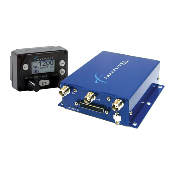
ADS-B FDL-978 Series and Lite Series Installation Manual Document No. 87343 Rev F Figure 3. FDL-978-RX Block Diagram (Typical) Figure 4. FDL-978 Series The main components of the FDL-978 Series are the FFS ADS-B Receiver and Transceiver Systems. They have identical connectors, pin-outs, size, and mounting requirements. These models have a DB-44 female connector, a Universal Serial Bus (USB) micro-AB maintenance connector, one Threaded Neill–Concelman (TNC) GPS antenna connector (87098-00-XXXX... - Page 22 ADS-B FDL-978 Series and Lite Series Installation Manual Document No. 87343 Rev F Satellite Based Augmentation System (SBAS) is referred to as Wide Area Augmentation System (WAAS) in the U.S. and throughout this manual. internal GPS/WAAS sensors in the FDL-978 and FDL-978 Lite Series are compatible with other SBAS’s (for example, EGNOS, MSAS, etc.).
-
Page 23: Tc978 Controller
ADS-B FDL-978 Series and Lite Series Installation Manual Document No. 87343 Rev F Personality Module Interface A personality module installed in the aircraft connector allows configuration settings to automatically be retrieved and set when a transceiver or receiver unit is removed and replaced in the aircraft. -
Page 24: Uat Antenna Requirements
ADS-B FDL-978 Series and Lite Series Installation Manual Document No. 87343 Rev F The TC978 is not required if the FDL-978-XVR is connected to a transmit controller (transponder) and/or display that can provide, as a minimum: • Mode A code entry and display •... -
Page 25: Technical Characteristics
ADS-B FDL-978 Series and Lite Series Installation Manual Document No. 87343 Rev F Technical Characteristics U.S. standard units of measure are the primary means of identifying dimensions, weights, etc. The equivalent metric values may also be shown in brackets (e.g. -
Page 26: Tc978 Controller
ADS-B FDL-978 Series and Lite Series Installation Manual Document No. 87343 Rev F Avionics Interface Type Description Controller Input/ Output 7 VDC power output, remote on/off discrete input, RS-485 serial interface to the TC978 GPS Input Input Serial (RS-232, RS-422, or RS-485) or ARINC 429 (ARINC... -
Page 27: Parts And Equipment
ADS-B FDL-978 Series and Lite Series Installation Manual Document No. 87343 Rev F 1.6 Parts and Equipment 1.6.1 FDL-978 Series Items *Models 87098-00 and 87098-10 are not recommended for new installations. The FDL-978 Series and optional installation kit part numbers are listed below:... - Page 28 ADS-B FDL-978 Series and Lite Series Installation Manual Document No. 87343 Rev F The items included in the TC978 Installation Kit (P/N 86964) are listed below: Item Description TC978 Mounting Adapter Bracket (circular hole adapter) Hose EPDM Rubber 5 mm ID – 8 mm OD Hose Connector 3/16 in Nylon Tee Hose Adapter Straight Nylon 3/16 –...
- Page 29 ADS-B FDL-978 Series and Lite Series Installation Manual Document No. 87343 Rev F The items included in the Blade Type Antenna Installation Kit (P/N 87003-00) are listed below: Part Number Description 87005 Blade Type UAT Antenna 86966 BNC RG142 Male Crimp Connector...
-
Page 30: Materials Required But Not Supplied
ADS-B FDL-978 Series and Lite Series Installation Manual Document No. 87343 Rev F Materials Required But Not Supplied The following items are required for proper installation but not supplied: • Wire and shielded wire • Circuit breaker • Ground terminals... -
Page 31: Series Installation
ADS-B FDL-978 Series and Lite Series Installation Manual Document No. 87343 Rev F SECTION 2 FDL-978 SERIES INSTALLATION This section provides general information for installing the FDL-978 Series and TC978 Controller into an aircraft. This section contains mounting dimensions, pin outs, and interface details pertaining to installation. -
Page 32: Series
ADS-B FDL-978 Series and Lite Series Installation Manual Document No. 87343 Rev F 2.2.1 FDL-978 Series The FDL-978 equipment is designed to be mounted in any convenient location in the cockpit, the cabin, or an avionics bay. Select a position in the aircraft that is not too close to any high external heat source. -
Page 33: Cooling Requirements
ADS-B FDL-978 Series and Lite Series Installation Manual Document No. 87343 Rev F Select a position in the panel that is not too close to any high external heat source. (The TC978 is not a significant heat source itself). Avoid sharp bends and placing the cables too near to the aircraft control cables. - Page 34 ADS-B FDL-978 Series and Lite Series Installation Manual Document No. 87343 Rev F J1 – Power and I/O Connector (DB-44) SIGNAL ELECTRICAL DESCRIPTION 10-40 VDC Aircraft Power Input Ground TC978 Controller Power Return 232 RxD2 RS-232 Serial Port 2 RS-232 Data In...
-
Page 35: Interface Details
ADS-B FDL-978 Series and Lite Series Installation Manual Document No. 87343 Rev F J1 – Power and I/O Connector (DB-44) SIGNAL ELECTRICAL DESCRIPTION 429 IN 1A ARINC 429 ARINC 429 Input Port 1A 429 IN 2B ARINC 429 ARINC 429 Input Port 2B... -
Page 36: Status Leds
ADS-B FDL-978 Series and Lite Series Installation Manual Document No. 87343 Rev F as well as in the FDL-978 Series. The installation configuration data in the PM (if present) is copied to the FDL-978 Series at power-up. Both the PM and the FDL-978-RX/XVR configuration data are stored during the installation configuration process. -
Page 37: Remote Power Control
ADS-B FDL-978 Series and Lite Series Installation Manual Document No. 87343 Rev F Name Description UAT Receive (GREEN) Blink ON Blinks ON when ADS-B data is received No UAT receptions 2.5.4 Remote Power Control The REM ON pin (J1-32) MUST be connected to ground when not using remote power control or a TC978 is not installed for the system to power on. -
Page 38: Configurable Serial Interfaces
ADS-B FDL-978 Series and Lite Series Installation Manual Document No. 87343 Rev F 2.5.6 Configurable Serial Interfaces There are nine configurable Serial Interfaces available on the FDL-978 Series: Six UART style Serial Port Interfaces (Ports 1, 2, 3, 4, 5, and 6), two ARINC 429 Input Interfaces (429 IN1 and 429 IN2), and one ARINC 429 Output Interface (429 OUT1). -
Page 39: Arinc 429 Ports
ADS-B FDL-978 Series and Lite Series Installation Manual Document No. 87343 Rev F Serial Channels SIGNAL ELECTRICAL DESCRIPTION J1-9 SGND4 Serial Ground Gnd Serial Ground J1-7 TxD6+ RS-422 Serial Port 6 Data Out+ RS-422/RS- J1-8** TxD6- Serial Port 6 Data Out-... -
Page 40: Air/Ground Input
ADS-B FDL-978 Series and Lite Series Installation Manual Document No. 87343 Rev F Discrete Inputs SIGNAL ELECTRICAL DESCRIPTION J1-27 AIR/GND Open/Ground I Air/Ground In (Squat Switch – configurable) J1-15 TRAF TEST Open/Ground I Traffic Test J1-12 ANONYMOUS Open/Ground Anonymous Mode MODE 2.5.7.1 Air/Ground Input... -
Page 41: Discrete Output
ADS-B FDL-978 Series and Lite Series Installation Manual Document No. 87343 Rev F In Anonymous Mode you are unable to receive Instrument Flight Rule (IFR) or Visual Flight Rule (VFR) separation services. Also potential loss of enhanced search and rescue benefits, and potential negative impacts to ADS-B IN applications could occur. -
Page 42: Maintenance Port Interface
ADS-B FDL-978 Series and Lite Series Installation Manual Document No. 87343 Rev F Time Mark from a GPS provides timing synchronization for ADS-B transmit messages. The Time Mark from an external GPS MUST be synchronized to UTC second epoch to operate correctly with the FDL-978-XVR. -
Page 43: Tc978 Controller Electrical Connections
ADS-B FDL-978 Series and Lite Series Installation Manual Document No. 87343 Rev F When Port 3 and Port 5 are configured and interfaced to other equipment (TC978 or display) the connections to the configured device must be temporarily disconnected to use the port for MPI purposes. -
Page 44: Tmap Bus
ADS-B FDL-978 Series and Lite Series Installation Manual Document No. 87343 Rev F 2.7.3 TMAP Bus TMAP is a proprietary protocol using RS-485 bi-directional serial bus between the TC978 and FDL-978-XVR. The TC978 RS-485 lines (TMAPA and TMAPB) are connected to the FDL-978- XVR RS-485 lines (TRxD3+ and TRxD3-) respectively. -
Page 45: Figure 8. Personality Module Assembly
ADS-B FDL-978 Series and Lite Series Installation Manual Document No. 87343 Rev F The following table shows the PM wire color connections to the DB-44 connector: Personality Module Interface SIGNAL ELECTRICAL DESCRIPTION PM WIRE COLOR J1-14 3.0 -3.6 VDC Personality Module Power... -
Page 46: Wiring Considerations
ADS-B FDL-978 Series and Lite Series Installation Manual Document No. 87343 Rev F Wiring Considerations Cables with solid cores should not be used. Cables should be selected based on the wear characteristics of their insulation material, including temperature rating, resistance to solvents and oils, and flammability. Most inexpensive commercial data cables have poor flammability properties. -
Page 47: Uat Antenna Ground Plane
ADS-B FDL-978 Series and Lite Series Installation Manual Document No. 87343 Rev F • In installations without a digital serial interface to the transponder, the FDL-978 and FDL- 978 Lite Series contains a Mode A receiver to receive Mode A/C Transponder control data from the transponder antenna through the UAT antennas. -
Page 48: Gps Antenna Installation
ADS-B FDL-978 Series and Lite Series Installation Manual Document No. 87343 Rev F Consider moving the FDL-978 Series and FDL-978 Lite Series closer to the antenna to minimize the losses in the antenna cable subject to the limits identified above. -
Page 49: Antenna Power
ADS-B FDL-978 Series and Lite Series Installation Manual Document No. 87343 Rev F 3. Antenna placement on the airframe should be optimized to ensure the sensor can take full advantage of a 5 degree mask angle. This includes consideration of antenna location with respect to blockage from all aircraft components at typical level cruising attitude, as well as minimizing the effects of aircraft shadowing during typical maneuvers. -
Page 50: Equipment Limitations
ADS-B FDL-978 Series and Lite Series Installation Manual Document No. 87343 Rev F Choose a point in the existing static pressure line that is as close as practical to the TC978. Cut the static pressure line, and use the supplied T fitting to connect the altitude encoder. Take care not to contaminate the inside of the static line when cutting or inserting the connectors. -
Page 51: Department Of Commerce Compliance
ADS-B FDL-978 Series and Lite Series Installation Manual Document No. 87343 Rev F TSO-C195a Certified installations must be approved by a Supplemental Type Certificate (STC) or Type Certificate (TC) “This article meets the minimum performance and quality control standards required by a technical standard order (TSO). - Page 52 ADS-B FDL-978 Series and Lite Series Installation Manual Document No. 87343 Rev F This page intentionally left blank 2-22 FFS Copyright © 2015 All rights reserved.
-
Page 54: Series Configuration And Checkout
ADS-B FDL-978 Series and Lite Series Installation Manual Document No. 87343 Rev F SECTION 3 FDL-978 SERIES CONFIGURATION AND CHECKOUT General This section contains installation configuration, checkout, and basic operating procedures. More detailed operating procedures are contained in the Pilot Guide/User Manual. -
Page 55: Display
ADS-B FDL-978 Series and Lite Series Installation Manual Document No. 87343 Rev F 3.1.2.1 Display The display shows the operating mode of the FDL-978 Lite Series and FDL-978-XVR, the reported pressure altitude, and the current Squawk Code and Call Sign/Flight ID. The pressure altitude is displayed as a Flight Level, which is the pressure altitude in hundreds of feet. - Page 56 ADS-B FDL-978 Series and Lite Series Installation Manual Document No. 87343 Rev F When airborne, the Controller should always be set to either ALT position. Aircraft installations should include a ground indication Squat Switch to automatically transmit ADS-B ground messages upon landing.
-
Page 57: Push Buttons
ADS-B FDL-978 Series and Lite Series Installation Manual Document No. 87343 Rev F Pos. Description The FDL-978 ADS-B equipment is placed in Transmission Mode with no pressure altitude reported in transmitted messages. The FDL-978 equipment automatically switches between Airborne and Ground Transmission Mode. - Page 58 ADS-B FDL-978 Series and Lite Series Installation Manual Document No. 87343 Rev F Button Description Pressing the FN button provides access to changing the Call Sign/Flight You may either directly rotate the CODE knob or press the ENT button and the first character of the Call Sign/Flight ID will be highlighted. Use the rotary CODE knob to select your choice of alpha-numeric characters.
- Page 59 ADS-B FDL-978 Series and Lite Series Installation Manual Document No. 87343 Rev F Button Description Pressing the FN button a third time allows the user to adjust the brightness level of the screen. Turning the CODE knob to the right will make the screen brighter.
-
Page 60: Code Knob
ADS-B FDL-978 Series and Lite Series Installation Manual Document No. 87343 Rev F 3.1.2.4 Code Knob The CODE knob is used to set Squawk Codes and Call Sign/Flight IDs. The FN button selects which item will be updated. Turning the knob will highlight the first digit on the display, then the digit can be changed as required. -
Page 61: Installation Setup And Configuration
ADS-B FDL-978 Series and Lite Series Installation Manual Document No. 87343 Rev F 3. Verify that the two UAT antenna coax center conductors are not shorted to its shield or aircraft ground. When the above conditions are verified, turn off the master power. Properly attach the external connectors to the FDL-978 Series, FDL-978 Lite Series, and TC978. -
Page 62: Fdl-978-Xvr Configuration Item Summary
ADS-B FDL-978 Series and Lite Series Installation Manual Document No. 87343 Rev F 3.3.1 FDL-978-XVR Configuration Item Summary Use the configuration setting lists below to document the system installation. Table 1. Serial and ARINC Port Configuration Settings Configuration Item Default... -
Page 63: Table 3. Display Output Configuration Settings
ADS-B FDL-978 Series and Lite Series Installation Manual Document No. 87343 Rev F Table 2. ADS-B Transmit Configuration Settings Configuration Item Default Setting ICAO Address (Mode S) VFR Call Sign (Flight ID) GPS SDA Level UNKNOWN GPS NACv Mode UNKNOWN... -
Page 64: Series Serial And Arinc Port Configuration Details
ADS-B FDL-978 Series and Lite Series Installation Manual Document No. 87343 Rev F Traffic Velocity Validation is not configurable on the TC978. Display Data Output is not configurable on the TC978. Refer to Section 3.5.4.13.3 for detailed information on determining the proper display output settings in this table. - Page 65 ADS-B FDL-978 Series and Lite Series Installation Manual Document No. 87343 Rev F Interface Description Display Output ADS-B traffic and FIS-B data output can be sent to one or more displays simultaneously. A display control can also be configured to provide the Control Input.
- Page 66 ADS-B FDL-978 Series and Lite Series Installation Manual Document No. 87343 Rev F Only ONE function can typically be set to either the input or output of each bi- directional Serial Port (2, 3, 5, or 6). If the serial port input is set to a function then the output should be set to ‘UNUSED’...
-
Page 67: Serial Port Input Configuration
ADS-B FDL-978 Series and Lite Series Installation Manual Document No. 87343 Rev F 3.3.2.1 Serial Port Input Configuration The following tables define the serial port input data formats and baud rate settings: Table 5. Serial Port Input Configuration Settings Setting... -
Page 68: Table 6. Serial Port Input Baud Rate Settings
ADS-B FDL-978 Series and Lite Series Installation Manual Document No. 87343 Rev F MPI setting names are listed first with TC978 configuration menu names in parenthesis (). Altitude input configuration of the GSL-71/SL70/R can affect the control output baud rate. When passing altitude information from these devices, the baud rate must be set to 9600. -
Page 69: Serial Port Output Configuration
ADS-B FDL-978 Series and Lite Series Installation Manual Document No. 87343 Rev F 3.3.2.2 Serial Port Output Configuration The following tables define the serial port output data formats and baud rate: Table 7. Serial Port Output Configuration Settings Setting Interface... -
Page 70: Arinc 429 Port Input Configuration
ADS-B FDL-978 Series and Lite Series Installation Manual Document No. 87343 Rev F When using the FFS Wi-Fi transceiver, ensure port is configured for Traffic Alert. Configure at baud rate of 38400 when using Chelton FlightLogic display. Ensure CSA bit is set per Section 3.5.4.13.3.2. -
Page 71: Table 11. Gps-743 Input Arinc Labels
ADS-B FDL-978 Series and Lite Series Installation Manual Document No. 87343 Rev F Maintenance port setting names listed first with TC978 configuration menu setting names in parenthesis (). Table 10. ARINC Port Input Speed Configuration Settings Setting Description Low speed ARINC 429 – 12.5 kBaud high High speed ARINC 429 –... -
Page 72: Table 13. Transpnder-Cntrl Input Arinc Labels
ADS-B FDL-978 Series and Lite Series Installation Manual Document No. 87343 Rev F Label Description PRAIM Satellite Deselect #1 PRAIM Satellite Deselect #2 Table 13. Transpnder-Cntrl Input ARINC Labels Label Description TCAS/ATC Control (Squawk Code and IDENT only) ATCRBS Control (Squawk Code and IDENT only) Call Sign/Flight ID Characters 1&2... -
Page 73: Arinc 429 Port Output Configuration
ADS-B FDL-978 Series and Lite Series Installation Manual Document No. 87343 Rev F Table 17.Traffic Format Input ARINC Labels Label Description TCAS Output – Receiver health in System Status Fault Summary – TA only mode set in RI field True Heading... -
Page 74: Table 20. Traffic Format Output Arinc Labels
ADS-B FDL-978 Series and Lite Series Installation Manual Document No. 87343 Rev F The ARINC 429 Output channel can be configured as the following: Table 20. Traffic Format Output ARINC Labels Label Description TCAS Output – Receiver health in System Status Fault Summary –... -
Page 75: Table 21. Gps-743 Output Labels Order
ADS-B FDL-978 Series and Lite Series Installation Manual Document No. 87343 Rev F Table 21. GPS-743 Output Labels Order Label Description GNSS Altitude Horizontal Dilution of Precision Vertical Dilution of Precision True Track Latitude Longitude Ground Speed Latitude Fine Longitude Fine... -
Page 76: Mpi Module Overview
Document No. 87343 Rev F MPI Module Overview The FreeFlight Systems (FFS) Automatic Dependent Surveillance – Broadcast (ADS-B) Maintenance Port Interface (MPI) module is a battery powered device that communicates with the aircraft’s ADS-B equipment maintenance port. It provides Wi-Fi connectivity to an Android device loaded with the free ADS-B MPI app. -
Page 77: Back Components
ADS-B FDL-978 Series and Lite Series Installation Manual Document No. 87343 Rev F The front of the MPI module consists of a male DB-9 connector. An MPI can be provided through Serial Port 3 or Port 5 on the ADS-B equipment DB-44 connector. -
Page 78: Terminal Program Interface
ADS-B FDL-978 Series and Lite Series Installation Manual Document No. 87343 Rev F 3.5.3 Terminal Program Interface The following 3.5.3 sub-sections describe interfacing directly to the MPI using a terminal interface program on a PC, like “Tera Term,” to enter MPI commands. Any of the four interface devices mentioned above can be used to interface to the PC. -
Page 79: Help Or ?" Command
ADS-B FDL-978 Series and Lite Series Installation Manual Document No. 87343 Rev F Command Description Display data from the altitude/air data input Display built-in test status comm Display communication ports’ status - continuous control Display control squawk and mode status... -
Page 80: Ads" Command
ADS-B FDL-978 Series and Lite Series Installation Manual Document No. 87343 Rev F 3.5.4.2 “ads” Command This command displays the data from the Altitude/Air Data input interface. 3.5.4.3 “bit” Command This command displays built-in-test information about the FDL-978 Series health. Example output is displayed below: 3.5.4.4 “comm”... -
Page 81: Control" Command
ADS-B FDL-978 Series and Lite Series Installation Manual Document No. 87343 Rev F 3.5.4.5 “control” Command This command displays the control, squawk and mode status including the Squawk Code, IDENT status, altitude control status, call sign, transmit control status and vertical status. -
Page 82: Rx Status" Command
ADS-B FDL-978 Series and Lite Series Installation Manual Document No. 87343 Rev F 3.5.4.9 “rx status” Command This command displays detailed status and other information about the ADS-B data being received by the FDL-978 Series. Example output is displayed below: The output displayed contains an initial section with general count information (current UTC second, receiver loop count, and receiver word count). -
Page 83: Cnfg" Command
ADS-B FDL-978 Series and Lite Series Installation Manual Document No. 87343 Rev F The fourth rx status section displays detailed ground station information. This information includes total number of ground stations being received and detailed information about the 10 closest ground stations. The detailed ground station information includes Latitude, Longitude, Site ID, time slot of last transmission, message count (Msgs), signal strength indication (SSI) in dbm, and ground station time out in seconds (TO). -
Page 84: Cnfgstatus" Command
ADS-B FDL-978 Series and Lite Series Installation Manual Document No. 87343 Rev F 3.5.4.11 “cnfgstatus” Command This command displays a summary of the Serial/ARINC port configuration status for various interfaces (GPS, Altitude, Control, Display, etc.). Details are shown on what port is configured and data reception status for each of the functional interfaces. -
Page 85: Serial And Arinc Port Settings
ADS-B FDL-978 Series and Lite Series Installation Manual Document No. 87343 Rev F 3.5.4.13.1 Serial and ARINC Port Settings This section describes the configuration settings for serial and ARINC port functionality. 3.5.4.13.1.1 “set serial in” Command This command sets the Serial Port Input configuration options. Help on this command is displayed by entering “set serial in ?”. -
Page 86: Set Arinc In" Command
ADS-B FDL-978 Series and Lite Series Installation Manual Document No. 87343 Rev F Refer to Section 3.3.2.2 for information on selecting serial output settings. Serial Port 4 is input ONLY and does not accept output settings. 87098-00 and 87098-10 Transceivers do not allow Serial Port 5 settings 3.5.4.13.1.3... -
Page 87: Ads-B Transmit Settings
ADS-B FDL-978 Series and Lite Series Installation Manual Document No. 87343 Rev F 3.5.4.13.2 ADS-B Transmit Settings This section describes configuration settings mainly for transmitting ADS-B messages. Some of these settings are relevant for receiver only units as well. 3.5.4.13.2.1 “set addr”... -
Page 88: Set Nacv" Command
ADS-B FDL-978 Series and Lite Series Installation Manual Document No. 87343 Rev F 3.5.4.13.2.4 “set nacv” Command This command sets the Navigation Accuracy Category for velocity (NACv) for the GPS input. Internal GPS should be set to 3 (auto). For external GPS units refer to the GPS manufacturer’s data for setting NACv. -
Page 89: Set Emit Cat" Command
ADS-B FDL-978 Series and Lite Series Installation Manual Document No. 87343 Rev F 3.5.4.13.2.6 “set emit cat” Command This command sets the emitter category of the aircraft and must be set to something other than the default of 0 (no aircraft type). This should be set for transceivers and receivers. -
Page 90: Set Threshold" Command
ADS-B FDL-978 Series and Lite Series Installation Manual Document No. 87343 Rev F 3.5.4.13.2.8 “set threshold” Command This command sets the groundspeed threshold which is used to determine when the aircraft is on the ground if an automatic means (Squat Switch) is not configured for the Light Aircraft (1) Emitter Category only. -
Page 91: Set Gpsant" Command
ADS-B FDL-978 Series and Lite Series Installation Manual Document No. 87343 Rev F 3.5.4.13.2.11 “set gpsant” Command This command sets the GPS antenna configuration. This should be set for transceivers but is not necessary for receivers. 3.5.4.13.2.12 “set modeArx” Command This command enables/disables Mode A code reception from the on-aircraft Mode A/C transponder. -
Page 92: Display Output Settings
ADS-B FDL-978 Series and Lite Series Installation Manual Document No. 87343 Rev F 3.5.4.13.3 Display Output Settings This section describes configuration settings for controlling traffic display output typically for legacy displays. 3.5.4.13.3.1 “set max trgs” Command This command sets the maximum number of targets to be sent on any configured serial or ARINC 429 port configured for traffic display output. -
Page 93: Set Displayout
ADS-B FDL-978 Series and Lite Series Installation Manual Document No. 87343 Rev F data to the display as directional traffic. This parameter should only be set to “disable” for legacy non-TSO-C195a displays without non-directional traffic symbols when occasional display of non-directional traffic is deemed to be unacceptable or misleading. -
Page 94: Configuration And Setup Using Tc978
ADS-B FDL-978 Series and Lite Series Installation Manual Document No. 87343 Rev F Configuration and Setup Using TC978 Do not use Configuration Mode during flight. The system should be configured during initial system installation by a qualified technician. The configuration items list in 3.3.1 should be used to document the system installation for future reference. -
Page 95: Aircraft Mode S (Or Icao) Address
ADS-B FDL-978 Series and Lite Series Installation Manual Document No. 87343 Rev F 3.6.2.1 Aircraft Mode S (or ICAO) Address The Mode S address is a 24 bit number assigned to the aircraft and is represented in a six character hexadecimal format. The CODE knob is used to change each character as required. -
Page 96: Groundspeed Threshold
ADS-B FDL-978 Series and Lite Series Installation Manual Document No. 87343 Rev F • Type C – The telephony designator of the aircraft operating agency, followed by the flight identification. The VFR Flight ID is an eight character alpha-numeric string. The CODE knob is used to change each character as required. -
Page 97: Aircraft (Emitter) Category
ADS-B FDL-978 Series and Lite Series Installation Manual Document No. 87343 Rev F 3.6.2.5 Aircraft (Emitter) Category The following options are offered for selecting aircraft (emitter) category: 1. Unknown 2. Light Fixed Wing 3. Medium Fixed Wing 4. Large Fixed Wing 5. -
Page 98: Serial In Channel X Data Type
ADS-B FDL-978 Series and Lite Series Installation Manual Document No. 87343 Rev F 3.6.2.7 Serial IN Channel X Data Type (X = channel number) The FDL-978-XVR can receive data via four serial channels. The following options are offered for selecting serial input type for each individual input serial... -
Page 99: Serial In Channel X Line Speed
ADS-B FDL-978 Series and Lite Series Installation Manual Document No. 87343 Rev F 3.6.2.8 Serial IN Channel X Line Speed (X = channel number) The following options are offered for selecting the serial input baud rate for each channel data type: 1. -
Page 100: Serial Out Channel X Line Speed
ADS-B FDL-978 Series and Lite Series Installation Manual Document No. 87343 Rev F The display screen is as shown below with one of the options from the list above. Rotate the CODE knob either clockwise or counterclockwise to display the options above and select the correct serial output type. -
Page 101: Arinc In Channel X Interface Speed
ADS-B FDL-978 Series and Lite Series Installation Manual Document No. 87343 Rev F The display screen is as shown below with one of the options from the list above. Rotate the CODE knob either clockwise or counterclockwise to display the options above and select the correct ARINC input type. -
Page 102: Arinc Out Chan 1 Interface Speed
ADS-B FDL-978 Series and Lite Series Installation Manual Document No. 87343 Rev F Rotate the CODE knob either clockwise or counterclockwise to display the options above and select the correct ARINC output type. Once selected, press the ENT button to confirm your selection and move to the next configuration item in the setup mode. -
Page 103: Gps Certification
ADS-B FDL-978 Series and Lite Series Installation Manual Document No. 87343 Rev F 3.6.2.16 GPS Certification The FDL-978-XVR needs a valid GPS source so that aircraft position can be transmitted in its ADS-B message. The GPS source is usually certified to a RTCA-DO178B software level as mandated by the governing FAA TSO. -
Page 104: Aircraft Length
ADS-B FDL-978 Series and Lite Series Installation Manual Document No. 87343 Rev F Rotate the CODE knob either clockwise or counterclockwise to display the options above and select the correct GPS certification level. Once selected, press the ENT button to confirm your selection and move to the next configuration item in the setup mode. -
Page 105: Gps Reference Position Offset
ADS-B FDL-978 Series and Lite Series Installation Manual Document No. 87343 Rev F 3.6.2.20 GPS Reference Position Offset There are three modes by which the GPS reference offset can be set: 1. Unknown 2. Auto set by GPS 3. Manual set here The display screen is as shown below with one of the options from the list above. -
Page 106: Mode A/C Receiver Sets Squawk
ADS-B FDL-978 Series and Lite Series Installation Manual Document No. 87343 Rev F Rotate the CODE knob either clockwise or counterclockwise to display the options above and select the correct antenna offset. Once selected, press the ENT button to confirm selection and move to the next configuration item in the setup mode. -
Page 107: Uat Antenna Diversity
ADS-B FDL-978 Series and Lite Series Installation Manual Document No. 87343 Rev F Rotate the CODE knob either clockwise or counterclockwise to display either “Yes” or “No” and select the correct option. Once selected, press the ENT button to confirm selection and move to the next configuration item in the setup mode. -
Page 108: Tc978 Test And Calibration
ADS-B FDL-978 Series and Lite Series Installation Manual Document No. 87343 Rev F TC978 Test and Calibration 3.7.1 Local Voltage Supply Test The TC978 Controller of the FDL-978-XVR utilizes a DC supply voltage of 5.5V to 8V. The display typically shows the supply voltage between 6.5V to 7.1V as shown below. - Page 109 ADS-B FDL-978 Series and Lite Series Installation Manual Document No. 87343 Rev F and the high altitude point adjusts the correspondence at the altitude limit of the encoder. Since the altitude limit of the encoder is likely to be higher than the service ceiling of the aircraft, it is sufficient to set the upper adjustment at the service ceiling of the aircraft.
-
Page 110: Pressure Altitude Reported
ADS-B FDL-978 Series and Lite Series Installation Manual Document No. 87343 Rev F 9. Read the primary altimeter value; rotate the CODE knob either clockwise or counterclockwise until the altitude displayed on the TC978 Controller matches the aircraft primary altimeter. Press the ENT button and the display will move to the high altitude set point and an altitude will be displayed as shown below. -
Page 111: Troubleshooting
ADS-B FDL-978 Series and Lite Series Installation Manual Document No. 87343 Rev F SECTION 4 TROUBLESHOOTING General This section provides information for troubleshooting problems that occur after FDL-978 Lite Series and FDL-978-XVR installations. This section contains information on how to use the units LEDs and TC978 Controller to troubleshoot installation problems. -
Page 112: Uat Status Led/Discrete Fault Indications
ADS-B FDL-978 Series and Lite Series Installation Manual Document No. 87343 Rev F 4.2.1 UAT Status LED/Discrete Fault Indications The status LED/discrete is an indicator of a warning or fault reported by the FDL-978 Lite Series and FDL-978-XVR. The status LED is visible on the units or the discrete may be connected to a cockpit annunciator. -
Page 113: Warning Messages
ADS-B FDL-978 Series and Lite Series Installation Manual Document No. 87343 Rev F Warning Messages If the FDL-978-XVR detects a malfunction, the icon appears to indicate that warning messages are present. Depending on the nature of the malfunction, the FDL-978-XVR may not transmit ADS-B messages. - Page 114 ADS-B FDL-978 Series and Lite Series Installation Manual Document No. 87343 Rev F Warning Potential Cause Troubleshooting Tx Power Low Transmitter power too low. Check antennas and cabling. Return for maintenance if problem persists. Tx PSU High Transmitter power supply Cycle power on the FDL-978 Lite Series and voltage too high.
-
Page 115: Rtca/Do-160 Environmental Qualifications
ADS-B FDL-978 Series and Lite Series Installation Manual Document No. 87343 Rev F SECTION 5 RTCA/DO-160 Environmental Qualifications U.S. standard units of measure are the primary means of identifying dimensions, weights, etc. The equivalent metric values may also be shown in brackets (e.g. -
Page 116: Tc978 Controller Do-160 Qualification
ADS-B FDL-978 Series and Lite Series Installation Manual Document No. 87343 Rev F TC978 Controller DO-160 Qualification Condition Para Category (DO-160F) Temperature and Altitude C4/C4/A4 Ground Survival Low Temperature 4.5.1 -67°F [-55°C] (C4) Short-Time Operating Low Temperature 4.5.1 -13°F [-25°C] (C4) Operating Low Temperature 4.5.2... -
Page 117: Serial Interface Specifications
ADS-B FDL-978 Series and Lite Series Installation Manual Document No. 87343 Rev F SECTION 6 SERIAL INTERFACE SPECIFICATIONS Two data formats may be selected to accept input from external Altitude sensors: • Encoder Altitude – Gray-code to serial altitude converters, etc. - Page 118 ADS-B FDL-978 Series and Lite Series Installation Manual Document No. 87343 Rev F alphanumeric ASCII fields. Each message field ends with a carriage return, line feed (CR = 0D0AH). All numeric fields are ASCII decimal, right justified and zero filled. If the ADC cannot supply data in a particular field, the field is filled with dashes ("-"...
-
Page 119: Ads-B Compliance
ADS-B FDL-978 Series and Lite Series Installation Manual Document No. 87343 Rev F SECTION 7 ADS-B COMPLIANCE ADS-B Parameters Supported: Comment Input Data Element (Use within the FDL-978-XVR) ICAO 24-bit Address Installation configuration Address Selection (ICAO vs Temporary) Anonymous discrete input... - Page 120 ADS-B FDL-978 Series and Lite Series Installation Manual Document No. 87343 Rev F Comment Input Data Element (Use within the FDL-978-XVR) 28 Capability Codes Installation configuration 29 TCAS Installed and Operational Installation configuration 30 TCAS/ACAS resolution advisory flag TCAS RA serial data input...
-
Page 121: Installation Drawings
ADS-B FDL-978 Series and Lite Series Installation Manual Document No. 87343 Rev F SECTION 8 INSTALLATION DRAWINGS Dimensions U.S. standard units of measure are the primary means of identifying dimensions, weights, etc. The equivalent metric values may also be shown in brackets (e.g. -
Page 122: Tc978 Controller Cut-Out Options
ADS-B FDL-978 Series and Lite Series Installation Manual Document No. 87343 Rev F Figure 16. TC978 Controller Dimensions TC978 Controller Cut-out Options The TC978 Controller can be fitted to either the compact mounting hole or a conventional 2.25 in (57mm) instrument cut-out. The compact mounting is a truncated 58 mm opening. - Page 123 ADS-B FDL-978 Series and Lite Series Installation Manual Document No. 87343 Rev F Figure 18. TC978 Conventional Cut-out FFS Copyright © 2015 All rights reserved.
- Page 124 ADS-B FDL-978 Series and Lite Series Installation Manual Document No. 87343 Rev F This page intentionally left blank FFS Copyright © 2015 All rights reserved.
-
Page 125: Typical Interconnect Diagrams
ADS-B FDL-978 Series and Lite Series Installation Manual Document No. 87343 Rev F SECTION 9 TYPICAL INTERCONNECT DIAGRAMS Figure 19. Internal GPS and Transponder FFS Copyright © 2015 All rights reserved. - Page 126 ADS-B FDL-978 Series and Lite Series Installation Manual Document No. 87343 Rev F Figure 20. External GPS and Transponder FFS Copyright © 2015 All rights reserved.
-
Page 127: Gps 430W/530W Configuration
ADS-B FDL-978 Series and Lite Series Installation Manual Document No. 87343 Rev F Figure 21. GPS 430W/530W Configuration FFS Copyright © 2015 All rights reserved. -
Page 128: Xpdr Monitor
ADS-B FDL-978 Series and Lite Series Installation Manual Document No. 87343 Rev F Figure 22. XPDR Monitor FFS Copyright © 2015 All rights reserved. - Page 129 ADS-B FDL-978 Series and Lite Series Installation Manual Document No. 87343 Rev F Figure 23. Altitude Encoder FFS Copyright © 2015 All rights reserved.
- Page 130 ADS-B FDL-978 Series and Lite Series Installation Manual Document No. 87343 Rev F Figure 24. Aspen Avionics Display FFS Copyright © 2015 All rights reserved.
- Page 131 ADS-B FDL-978 Series and Lite Series Installation Manual Document No. 87343 Rev F Figure 25. Alternate Displays FFS Copyright © 2015 All rights reserved.
- Page 132 ADS-B FDL-978 Series and Lite Series Installation Manual Document No. 87343 Rev F Figure 26. Alternate Displays (Cont’d) Figure 27. GPS ARINC-743 PRAIM FFS Copyright © 2015 All rights reserved.
- Page 133 ADS-B FDL-978 Series and Lite Series Installation Manual Document No. 87343 Rev F Figure 28. Serial Aircraft Wi-Fi Module with Display FFS Copyright © 2015 All rights reserved.
-
Page 134: Fdl-978-Rx Receiver With Internal Gps
ADS-B FDL-978 Series and Lite Series Installation Manual Document No. 87343 Rev F Figure 29. FDL-978-RX Receiver with Internal GPS 9-10 FFS Copyright © 2015 All rights reserved. -
Page 135: Section 10 Maintenance Interface Diagrams
ADS-B FDL-978 Series and Lite Series Installation Manual Document No. 87343 Rev F SECTION 10 MAINTENANCE INTERFACE DIAGRAMS Section 12.12.1 describes the various FDL-978 Lite Series configuration and setup options via the MPI. The diagrams below provide a pictorial representation of these available options for accessing the maintenance port of the FDL-978 Lite Series and FDL-978-XVR. - Page 136 ADS-B FDL-978 Series and Lite Series Installation Manual Document No. 87343 Rev F Figure 32. Serial-to-Wi-Fi MPI 10-2 FFS Copyright © 2015 All rights reserved.
- Page 137 ADS-B FDL-978 Series and Lite Series Installation Manual Document No. 87343 Rev F Figure 33. Serial-to-Wi-Fi Aircraft Module Figure 34. Optional Discrete Inputs/Outputs FFS Copyright © 2015 All rights reserved. 10-3...
- Page 138 ADS-B FDL-978 Series and Lite Series Installation Manual Document No. 87343 Rev F This page intentionally left blank 10-4 FFS Copyright © 2015 All rights reserved.
-
Page 139: Section 11 Warning Disclaimer
ADS-B FDL-978 Series and Lite Series Installation Manual Document No. 87343 Rev F SECTION 11 WARNING DISCLAIMER The FDL-978 Series provides FIS-B information that can be used as an aid for situational awareness only. FIS-B information provided must be used for advisory use only and should not be used for flight safety critical information and operation. - Page 140 ADS-B FDL-978 Series and Lite Series Installation Manual Document No. 87343 Rev F This page intentionally left blank 11-2 FFS Copyright © 2015 All rights reserved.
-
Page 141: Section 12 Fdl-978 Lite Series
ADS-B FDL-978 Series and Lite Series Installation Manual Document No. 87343 Rev F SECTION 12 FDL-978 LITE SERIES 12.1 General System Description The FDL-978 Lite Series includes the FDL-978-XVRL Transceiver (ADS-B Out & In) with FWF-125 Wi-Fi Module and the FDL-978-TXL Transmitter (ADS-B Out only). The FDL-... -
Page 142: Fdl-978-Txl
ADS-B FDL-978 Series and Lite Series Installation Manual Document No. 87343 Rev F The following is a short summary of the features: Internal GPS Models have an internal GPS/WAAS sensor and a single antenna input with a TNC connector. Status LEDs Four status LEDs (ST –... - Page 143 ADS-B FDL-978 Series and Lite Series Installation Manual Document No. 87343 Rev F Figure 36. FDL-978-TXL Wi-Fi MPI Block Diagram (Typical) The block diagram shown in Figure 37 identifies a TC978 Controller, an FDL-978-XVRL, FWF- 125 Wi-Fi Transceiver, bottom UAT antenna, and a GPS antenna. Additionally, connections are shown to an external altitude sensor (shared with the transponder), the transponder suppression bus, and an air/ground detection switch.
-
Page 144: Technical Characteristics
ADS-B FDL-978 Series and Lite Series Installation Manual Document No. 87343 Rev F 12.2 Technical Characteristics U.S. standard units of measure are the primary means of identifying dimensions, weights, etc. The equivalent metric values may also be shown in brackets (e.g. -
Page 145: Parts And Equipment
ADS-B FDL-978 Series and Lite Series Installation Manual Document No. 87343 Rev F 12.3 Parts and Equipment 12.3.1 FDL-978 Lite Series Items The items included in the FDL-978-XVRL Ship Kit (P/N 87098-00-FX0L-KIT) are listed below: Part Number Description 87098-00-FX0L FDL-978-XVRL Transceiver... - Page 146 ADS-B FDL-978 Series and Lite Series Installation Manual Document No. 87343 Rev F The items included in the FDL-978-TXL Ship Kit (P/N 87098-00-FT0L-KIT) are listed below: Part Number Description 87098-00-FT0L FDL-978-TXL Transmitter 87349 TC978 Controller 87874-00 Kit, Installation, TX Lite...
-
Page 147: Installation
ADS-B FDL-978 Series and Lite Series Installation Manual Document No. 87343 Rev F 12.4 Installation This section provides general information for installing the FDL-978 Lite Series into an aircraft. This section contains mounting dimensions, pin outs, and interface details pertaining to installation. -
Page 148: Electrical Connections
ADS-B FDL-978 Series and Lite Series Installation Manual Document No. 87343 Rev F 12.7 Electrical Connections 12.7.1 Interface – DB-44 Pinout J1 - Power and I/O Connector (DB-44) SIGNAL ELECTRICAL DESCRIPTION 10-40 VDC Aircraft Power Input Ground TC978 Controller Power Return... -
Page 149: Interface Details
ADS-B FDL-978 Series and Lite Series Installation Manual Document No. 87343 Rev F J1 - Power and I/O Connector (DB-44) SIGNAL ELECTRICAL DESCRIPTION REM ON Open/Ground Remote Power Control (Ground: ON, Open: OFF) Control Data Out RS-232 Control Data RS-232 Data Out... -
Page 150: Altitude Input Data Interface
ADS-B FDL-978 Series and Lite Series Installation Manual Document No. 87343 Rev F J1 - Power and I/O Connector (DB-44) SIGNAL ELECTRICAL DESCRIPTION Control Data In RS-232 Control Data RS-232 Data In Control Data RS-232 Control Data RS-232 Data Out... -
Page 151: Wi-Fi Module Or Maintenance Port Interface
ADS-B FDL-978 Series and Lite Series Installation Manual Document No. 87343 Rev F 12.7.11 Wi-Fi Module or Maintenance Port Interface The Wi-Fi Module interface is used to connect to the FWF-125 Wi-Fi Module (FDL-978-XVRL only) for receiving ADS-B TIS/FIS data wirelessly on the pilots PED (e.g. iPad or Android device) through a Wi-Fi connection. -
Page 152: Installation Setup And Configuration
ADS-B FDL-978 Series and Lite Series Installation Manual Document No. 87343 Rev F 12.12 Installation Setup and Configuration 12.12.1 FDL-978 Lite Series Configuration Item Summary Table 22. Serial Port Configuration Settings Configuration Item Default Setting Altitude Encoder (Port 4) IN Function... -
Page 153: Altitude Input Interface
ADS-B traffic and FIS-B data is output (FDL-978-XVRL only) on the Wi-Fi Module/MPI Port. The FreeFlight Systems Wi-Fi Module (FWF-125) connects to this port and is used to connect to various tablet applications (e.g. ADS-B MPI and FFS ADS-B View apps) and display traffic and weather data. -
Page 154: Configuration And Setup Using Tc978
ADS-B FDL-978 Series and Lite Series Installation Manual Document No. 87343 Rev F FDL-978-TXL Transmitter A female DB-9 connector should be mounted in the aircraft to this port for easy Maintenance Port Interface (MPI) access. The DB-9 connector allows connection of a battery powered Serial-... -
Page 155: Aircraft Mode S (Or Icao) Address
ADS-B FDL-978 Series and Lite Series Installation Manual Document No. 87343 Rev F All other options during the TC978 Configuration Mode are ignored and reset and returned to the factory settings. The FDL-978 Lite Series is preconfigured to simplify the installation and configuration process. -
Page 156: Vfr Flight Id
ADS-B FDL-978 Series and Lite Series Installation Manual Document No. 87343 Rev F The VFR Squawk Code is a 12 bit number and is represented as a four character octal number. The CODE knob is used to change each character as required. Each character of the Squawk Code is a number between 0 and 7. -
Page 157: Aircraft (Emitter) Category
ADS-B FDL-978 Series and Lite Series Installation Manual Document No. 87343 Rev F 1. Unknown 2. 30 knots 3. 40 knots 4. 50 knots 5. 60 knots 6. 70 knots 7. 80 knots 8. 90 knots 9. 100 knots 10. 120 knots This only applies to an Emitter Category of Light Aircraft –... -
Page 158: Squat Switch Type
ADS-B FDL-978 Series and Lite Series Installation Manual Document No. 87343 Rev F 12.13.2.6 Squat Switch Type Rotate the CODE knob either clockwise or counterclockwise to display the options below and select the correct Squat Switch type. Once selected, press the ENT button to confirm your selection and move to the next configuration item in the setup mode. -
Page 159: Aircraft Width
ADS-B FDL-978 Series and Lite Series Installation Manual Document No. 87343 Rev F 12.13.2.9 Aircraft Width The aircraft width can be set from 1 meter to 80 meters by rotating the CODE knob either clockwise or counterclockwise to display the correct width. Once selected, press the ENT button to confirm selection and move to the next configuration item in the setup mode. -
Page 160: Tc978 Test And Calibration
ADS-B FDL-978 Series and Lite Series Installation Manual Document No. 87343 Rev F The antenna lateral offset has the following options that can be selected: 1. Unknown 2. Left 0-2 meters 3. Left 2-4 meters 4. Left 4+ meters 5. Central 6. -
Page 161: Typical Interconnect Diagrams
ADS-B FDL-978 Series and Lite Series Installation Manual Document No. 87343 Rev F 12.20 Typical Interconnect Diagrams Figure 38. FDL-978-XVRL (Typical) FFS Copyright © 2015 All rights reserved. 12-21... -
Page 162: Table 24. Typical Transponder Connections
ADS-B FDL-978 Series and Lite Series Installation Manual Document No. 87343 Rev F Figure 39. FDL-978-TXL (Typical) Table 24. Typical Transponder Connections TRANSPONDER ALT OUT REMOTE OUT REMOTE IN SUPPRESSION NOTE GTX-327/32 TxD1 pin 20 Suppress IO pin Software version 2.10 or later... -
Page 163: Maintenance Interface Diagrams
ADS-B FDL-978 Series and Lite Series Installation Manual Document No. 87343 Rev F These connections are typical. If serial ports shown are being used then other ports may be available to configure and use or an alternate interface to get common altitude data may be necessary. - Page 164 ADS-B FDL-978 Series and Lite Series Installation Manual Document No. 87343 Rev F This page intentionally left blank 12-24 FFS Copyright © 2015 All rights reserved.
-
Page 165: Section 13 Limited Warranty
(B) THE WARRANTY CARD SUPPLIED WITH THE PRODUCT MUST BE COMPLETED AND RETURNED TO FREEFLIGHT WITHIN 15 DAYS OF INSTALLATION OF THE PRODUCT IN ORDER FOR THIS WARRANTY TO BECOME EFFECTIVE. (C) THE PRODUCT IS SOLD AND INSTALLED BY AN AUTHORIZED DEALER. A LIST OF ALL AUTHORIZED FREEFLIGHT DEALERS MAY BE OBTAINED FROM FREEFLIGHT. . - Page 166 ADS-B FDL-978 Series and Lite Series Installation Manual Document No. 87343 Rev F This page intentionally left blank 13-2 FFS Copyright © 2015 All rights reserved.
- Page 168 For additional product information and specifications, please visit our website at: www.freeflightsystems.com 3700 Interstate 35 South • Waco, Texas 76706-3756 USA US: 800.487.4662 • International: +1.254.662.0000 Made in USA...
Need help?
Do you have a question about the ADS-B FDL-978 Series and is the answer not in the manual?
Questions and answers