Sign In
Upload
Manuals
Brands
Daikin Manuals
Air Conditioner
FTKS25DVM
Daikin FTKS25DVM Inverter Wall-Mounted AC Manuals
Manuals and User Guides for Daikin FTKS25DVM Inverter Wall-Mounted AC. We have
6
Daikin FTKS25DVM Inverter Wall-Mounted AC manuals available for free PDF download: Service Manual, Operation Manual
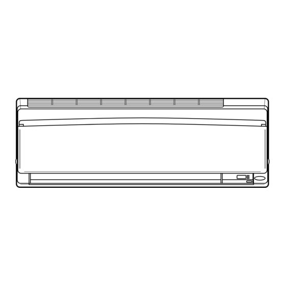
Daikin FTKS25DVM Service Manual (456 pages)
Super Multi Plus E-Series
Brand:
Daikin
| Category:
Air Conditioner
| Size: 8 MB
Table of Contents
Table of Contents
4
Part 5 Function
4
Introduction
9
Safety Cautions
9
Used Icons
13
Part 1 List of Functions
14
List of Functions
14
Cooling Only
15
Heat Pump
22
Part 2 Specifications
30
Cooling Only
31
Indoor Units
35
Ceiling Mounted Cassette Type
44
Ceiling Suspended Type
46
Heat Pump
47
Printed Circuit Board Connector Wiring Diagram
66
Outdoor Unit
67
Printed Circuit Board Connector Wiring Diagram
67
BP Unit
72
Wall Mounted Type 20/25/35 Class
73
Wall Mounted Type 50/60/71 Class
75
Duct Connected Type
77
Floor / Ceiling Suspended Dual Type
79
Floor Standing Type
82
Ceiling Mounted Cassette 600×600 Type
85
Ceiling Mounted Cassette Type (950×950)
88
Ceiling Mounted Built-In Type
91
Ceiling Suspended Type
93
Refrigerant Circuit
96
Outdoor Units
97
Refrigerant Circuit
97
BP Units
99
Functional Parts Layout
100
Outdoor Units
100
Refrigerant Flow for each Operation Mode
101
Cooling Operation
101
Heating Operation
102
Cooling Oil Return Operation
103
Heating Oil Return Operation & Defrost Operation
104
Part 5 Function
106
Operation Mode
107
Compressor PI Control
108
Basic Control
108
Normal Operation
108
Compressor PI Control
109
Electronic Expansion Valve PI Control
112
Cooling Operation Fan Control
113
Special Control
114
Startup Control
114
Oil Return Operation
115
Defrosting Operation
117
Pump-Down Residual Operation
118
Restart Standby
118
Stopping Operation
119
Protection Control
120
High Pressure Protection Control
120
Low Pressure Protection Control
121
Discharge Pipe Protection Control
122
Inverter Protection Control
123
Freeze-Up Protection Control
124
Dew Condensation Prevention Control
125
Other Control
126
Demand Operation
126
Heating Operation Prohibition
126
BP Unit Control
127
BP Unit Command Conversion
127
BP Unit Electronic Expansion Valve Control
128
Full Closing of Electronic Expansion Valves
129
SH Control in Cooling Operation
130
SC Control in Heating Operation
131
Heat Exchanger Isothermal Control in Heating Operation
131
Indoor Unit (RA Models)
132
Power-Airflow Dual Flaps, Wide Angle Louvers and Auto-Swing
132
Fan Speed Control for Indoor Units
133
Programme Dry Function
134
Automatic Operation
135
Thermostat Control
136
Night Set Mode
137
ECONO Mode
138
MOLD PROOF Operation
138
INTELLIGENT EYE (Wall Mounted Type Only)
139
HOME LEAVE Operation
141
Inverter POWERFUL Operation
142
Other Functions
143
Indoor Unit (Skyair Models)
145
Function Outline
145
Electric Function Parts
146
Function Details
147
Function
148
Drain Pump Control
148
Test Operation
158
Procedure and Outline
159
Test Operation
159
Check Operation
162
Outdoor Unit PCB Layout
164
Field Setting
165
Field Setting from Outdoor Unit
165
Setting by Dip Switches
165
Detail of Setting Mode
174
Setting of Low Noise Operation and Demand Operation
176
Setting of Refrigerant Additional Charging Operation
180
Field Setting for Skyair Indoor Unit
183
Explanation
183
Field Setting
184
Wired Remote Control
184
Initial Setting Contents
185
Infrared Remote Control
185
Local Setting Mode Number
186
Detailed Explanation of Setting Modes
187
Centralized Group No. Setting
191
Maintenance Mode Setting
192
Test Operation and Field Setting for RA Indoor Unit
193
Test Operation from the Remote Control
193
Jumper Settings
194
System Configuration
195
Operation Instructions
196
System Configuration
196
Instruction
197
RMXS Series
197
Wall Mounted, Duct, Floor/Ceiling, Floor Standing Type
198
Safety Precautions
199
Installation Site
200
Electrical Work
200
Names of Parts
201
Remote Control
203
Indoor Unit
213
Preparation before Operation
219
To Set the Clock
221
Auto Dry Cool Heat Fan Operation
222
To Change the Air Flow Rate Setting
223
Adjusting the Air Flow Direction
224
Air Flow Selection
229
Powerful Operation
232
Outdoor Unit Silent Operation
233
Econo Operation
234
Intelligent Eye Operation
238
Timer Operation
242
To Use on Timer Operation
243
To Combine on Timer and off Timer
243
Note for Multi System
244
Priority Room Setting
245
Care and Cleaning
246
Air Filter
247
Before a Long Idle Period
248
Front Panel
249
Front Grille
252
Cleaning the Air Filter
255
Troubleshooting
265
These Cases Are Not Troubles
265
Check Again
266
Ceiling Mounted Cassette Type
268
Temperature Setting
273
Fan Speed Control
273
Ceiling Mounted Built-In Type
290
Ceiling Suspended Type
300
Operation Range
303
Caution for Diagnosis
315
Troubleshooting with the Operation Lamp (RA Indoor Unit)
315
Troubleshooting with the LED on the Skyair Indoor Unit
316
Troubleshooting with the LED on the Outdoor Unit
317
Troubleshooting with the LED on the BP Unit
318
Service Check Function
319
RA Indoor Unit Infrared Remote Control
319
Skyair Indoor Unit INSPECTION/TEST Button
323
Skyair Indoor Unit Wired Remote Control
324
Skyair Indoor Unit Infrared Remote Control
325
Sky Air Indoor Unit Error Codes and LED Indication
327
Skyair Indoor Unit Error Codes and LED Indication
327
Malfunction Code Indication by Outdoor Unit PCB
328
List of Malfunction Code
332
Troubleshooting for RA Indoor Unit
334
Indoor Unit PCB Abnormality
334
Freeze-Up Protection Control or High Pressure Control
335
Fan Motor or Related Abnormality
337
Thermistor or Related Abnormality (Indoor Unit)
340
Shutter Drive Motor / Shutter Limit Switch Abnormality
341
Check
342
Thermistor Resistance Check
343
Hall IC Check
344
Troubleshooting for Skyair Indoor Unit
345
Indoor Unit PCB Abnormality
345
Malfunction of Drain Water Level System (Float Type)
346
Malfunction of Drain System
348
Indoor Unit Fan Motor Lock
349
Malfunction of Indoor Unit Fan Motor
350
Swing Flap Motor Malfunction / Lock
352
Malfunction of Capacity Setting
354
Malfunction of Heat Exchanger Thermistor (R2T)
355
Malfunction of Heat Exchanger Thermistor (R3T)
356
Malfunction of Suction Air Thermistor
357
Malfunction of Remote Control Thermistor
358
Transmission Error (between Indoor Unit and Remote Control)
359
Transmission Error (between Main and Sub Remote Control)
359
Transmission Error (between Main and Sub Remote Control)
360
Malfunction of Field Setting Switch
361
Check
362
Troubleshooting for BP Unit
364
Malfunction of Electronic Expansion Valve
364
Faulty BP Unit PCB
365
Faulty BP Liquid or Gas Pipe Thermistor
366
Transmission Error between Indoor Unit and BP Unit
367
Transmission Error between Outdoor Unit and BP Unit
369
Check
370
Troubleshooting for Outdoor Unit
371
Faulty Outdoor Unit PCB
371
Actuation of High Pressure Switch
372
Actuation of Low Pressure Sensor
374
Compressor Motor Lock
376
Malfunction of Outdoor Unit Fan Motor
377
Malfunction of Moving Part of Electronic Expansion Valve (Y1E, Y3E)
378
Abnormal Discharge Pipe Temperature
380
Refrigerant Overcharged
381
Malfunction of Thermistor for Outdoor Air (R1T)
382
Malfunction of Discharge Pipe Thermistor (R2T)
383
Malfunction of Thermistor (R3T, R5T) for Suction Pipe1, 2
384
Malfunction of Thermistor (R4T) for Outdoor Unit Heat Exchanger
385
Malfunction of Thermistor (R7T) for Outdoor Unit Liquid Pipe
386
Malfunction of Subcooling Heat Exchanger Thermistor (R6T)
387
Malfunction of High Pressure Sensor
388
Malfunction of Low Pressure Sensor
389
Malfunction of PCB
390
Malfunction of Inverter Radiating Fin Temperature Rise
391
Inverter Compressor Abnormal
392
Inverter Current Abnormal
393
Inverter Start up Error
394
Malfunction of Transmission between Inverter and Control PCB
395
High Voltage of Capacitor in Main Inverter Circuit
396
Malfunction of Inverter Radiating Fin Temperature Rise Sensor
397
Faulty Combination of Inverter and Fan Driver
398
Low Pressure Drop Due to Refrigerant Shortage or Electronic Expansion Valve Failure
399
Power Supply Insufficient or Instantaneous Failure
401
Check Operation Not Executed
403
Malfunction of Transmission between Indoor Units and Outdoor Units
404
Malfunction of Transmission between Remote Control and Indoor Unit
406
Malfunction of Transmission between Main and Sub Remote Controls
407
Malfunction of Transmission between Indoor and Outdoor Units in the same System
408
Excessive Number of Indoor Units
410
Address Duplication of Central Remote Control
411
Malfunction of Transmission between Central Remote Control and Indoor Unit
412
System Is Not Set yet
414
Malfunction of System, Refrigerant System Address Undefined
415
Check
416
Thermistor Resistance / Temperature Characteristics
419
Pressure Sensor
421
Method of Replacing the Inverter's Power Transistors Modules
422
Part 9 Appendix
425
Piping Diagrams
426
Outdoor Units
426
BP Units
427
Indoor Units
428
Wiring Diagrams
434
Outdoor Units
434
BP Units
436
Indoor Units
438
Index
447
Drawings & Flow Charts
453
Advertisement
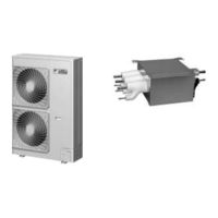
Daikin FTKS25DVM Service Manual (403 pages)
Super Multi NX D/E Series
Brand:
Daikin
| Category:
Air Conditioner
| Size: 22 MB
Table of Contents
Table of Contents
4
Introduction
8
Safety Cautions
8
Used Icons
12
Part 1 List of Functions
14
List of Functions
15
Cooling Only
15
Heat Pump
23
Part 2 Specifications
30
Indoor Units - Cooling Only
31
Duct Connected Type
39
Outdoor Units - Cooling Only
45
Indoor Units - Heat Pump
51
Floor Standing Type
59
Outdoor Units - Heat Pump
61
Part 3 Printed Circuit Board Connector Wiring Diagram
64
Printed Circuit Board Connector Wiring Diagram
65
Wall Mounted Type
65
Display Pcb
68
Duct Connected Type
69
Floor / Ceiling Suspended Dual Type
71
Floor Standing Type
74
Ceiling Mounted Cassette Type (600×600)
77
Outdoor Units - E Series (50-58 Class, 80-100 Class)
80
Outdoor Units - E Series (68-75 Class)
83
Outdoor Units - D Series
86
Part 4 Function and Control
90
Main Functions
91
Frequency Principle
91
Power-Airflow Dual Flaps, Wide Angle Louvers and Auto-Swing
93
Fan Speed Control for Indoor Units
94
Programme Dry Function
95
Automatic Operation
96
Thermostat Control
97
Night Set Mode
98
ECONO Mode
99
MOLD PROOF Operation
100
INTELLIGENT EYE (Wall Mounted Type Only)
101
HOME LEAVE Operation
103
Inverter POWERFUL Operation
104
Other Functions
105
Function of Main Structural Parts
107
Main Structural Parts
107
Function of Thermistor
108
Heat Pump Model
108
Cooling Only Model
110
Control Specification
112
Mode Hierarchy
112
Frequency Control
113
Controls at Mode Changing / Start-Up
116
Discharge Pipe Temperature Control
117
Input Current Control
117
Freeze-Up Protection Control
118
Heating Peak-Cut Control
118
Fan Control
119
Liquid Compression Protection Function 2
119
Defrost Control
120
Low Hz High Pressure Limit
121
Electronic Expansion Valve Control
121
Malfunctions
125
Forced Operation Mode
126
Wiring-Error Check
127
Additional Function
129
Part 5 Operation Manual
132
System Configuration
133
Operation Instructions
133
Instruction
134
FTK(X)S, CDK(X)S, FDK(X)S, FLXS, FVXS Series
134
Safety Precautions
135
Installation Site
136
Electrical Work
136
Outdoor Unit
138
Remote Controller
139
Names of Parts
143
Indoor Unit
143
Preparation before Operation
155
To Change the Air Flow Rate Setting
159
Adjusting the Air Flow Direction
160
Air Flow Selection
167
Powerful Operation
168
Outdoor Unit Quiet Operation
169
Econo Operation
170
Intelligent Eye Operation
174
Timer Operation
178
Note for Multi System
180
Priority Room Setting
181
Care and Cleaning
182
Front Panel
182
Air Filter
183
Before a Long Idle Period
184
Front Grille
188
Cleaning the Air Filter
191
Trouble Shooting
199
Ffq 25/35/50/60 B
202
Safety Considerations
204
Operation Range
205
Operation Procedure
206
Optimum Operation
208
Air Conditioner
210
Part 6 Service Diagnosis
214
Caution for Diagnosis
215
Troubleshooting with Operation Lamp
215
Problem Symptoms and Measures
217
Service Check Function
218
Code Indication on the Remote Controller
221
Error Codes and Description of Fault
221
Troubleshooting
222
Indoor Units
222
Outdoor Units
223
Indoor Unit PCB Abnormality
224
Freeze-Up Protection Control or High Pressure Control
225
Fan Motor or Related Abnormality
227
Ac Motor
227
DC Motor
228
Thermistor or Related Abnormality (Indoor Unit)
230
Shutter Drive Motor / Shutter Limit Switch Abnormality
231
Signal Transmission Error (between Indoor and Outdoor Units)
232
Unspecified Voltage (between Indoor and Outdoor Units)
234
Freeze-Up Protection Control
235
Outdoor Unit PCB Abnormality
237
OL Activation (Compressor Overload)
238
Compressor Lock
239
DC Fan Lock
241
Input over Current Detection
242
Four Way Valve Abnormality
244
Discharge Pipe Temperature Control
246
High Pressure Control in Cooling
247
Compressor Sensor System Abnormality
249
Position Sensor Abnormality
251
CT or Related Abnormality
252
Thermistor or Related Abnormality (Outdoor Unit)
254
Electrical Box Temperature Rise
256
Radiation Fin Temperature Rise
260
Output over Current Detection
264
Insufficient Gas
266
Low-Voltage Detection or Over-Voltage Detection
270
Signal Transmission Error (on Outdoor Unit PCB)
271
Anti-Icing Function in Other Rooms / Unspecified Voltage (between Indoor and Outdoor Units)
272
Check
273
How to Check
273
Electronic Expansion Valve Check
274
Four Way Valve Performance Check
275
Thermistor Resistance Check
276
Installation Condition Check
277
Discharge Pressure Check
278
Power Supply Waveforms Check
279
Inverter Units Refrigerant System Check
279
Capacitor Voltage Check
280
Power Transistor Check
280
Main Circuit Electrolytic Capacitor Check
281
Hall IC Check
282
Part 7 Removal Procedure
284
Outdoor Unit - E Series (50 / 52 / 58 Class)
285
Removal of the Panels and Plates
285
Removal of the Electrical Box
290
Removal of the PCB
297
Removal of the Propeller Fan / Fan Motor
303
Removal of the Sound Blanket
305
Removal of Electronic Expansion Valve Coil, Four Way Valve Coil and Thermistor
309
Removal of the Distributor
312
Removal of the Four Way Valve
313
Removal of the Compressor
314
Outdoor Unit - E Series (68 / 71 / 75 Class), D Series
316
Removal of the Outer Panels
316
Removal of the Electrical BOX
317
Removal of the PCB
321
Removal of the Fan Motor
324
Removal of the Sound Blanket
325
Electronic Expansion Valve Coil and Thermistor
326
Solenoid Valve
326
Removal of the Four Way Valve, Solenoid Valve and Shunt
328
Removal of the Solenoid Valve and Shunt
329
Removal of the Compressor
330
Outdoor Unit - E Series (80 / 90 / 100 Class)
331
Removal of Outer Panels
331
Removal of the Electrical Box
347
Removal of PCB
353
Removal of Fan Motor
357
Removal of Coils / Thermistors
358
Removal of Sound Blanket
364
Removal of Compressor
367
Part 8 Others
368
Others
369
Test Run from the Remote Controller
369
Jumper Settings
370
Application of Silicon Grease to a Power Transistor and a Diode Bridge
371
Part 9 Appendix
372
Piping Diagrams
373
Indoor Units
373
Outdoor Units
377
Wiring Diagrams
383
Indoor Units
383
Outdoor Units
389
Index
394
Drawings & Flow Charts
400
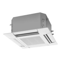
Daikin FTKS25DVM Service Manual (226 pages)
Inverter Pair Wall Mounted Type
Brand:
Daikin
| Category:
Air Conditioner
| Size: 9 MB
Table of Contents
Table of Contents
3
Introduction
6
Safety Cautions
6
Used Icons
10
Part 1 List of Functions
12
List of Functions
13
R-410A Models
13
Models
16
Part 2 Specifications
20
Specifications
21
Cooling Only
21
Heat Pump
26
Part 3 Printed Circuit Board Connector Wiring Diagram
30
Printed Circuit Board Connector Wiring Diagram
31
Indoor Unit
31
Outdoor Unit
37
Part 4 Function and Control
40
Main Functions
41
Frequency Principle
41
Airflow Direction Control
43
Fan Speed Control for Indoor Units
44
Programme Dry Function
45
Automatic Operation
46
Thermostat Control
47
NIGHT SET Mode
48
ECONO Mode
49
MOLD PROOF Operation
50
Intelligent Eye
51
Inverter POWERFUL Operation
53
Other Functions
54
Function of Thermistor
55
Heat Pump Model
55
Cooling Only Model
56
Control Specification
57
Mode Hierarchy
57
Frequency Control
58
Controls at Mode Changing / Start-Up
60
Preheating Operation
60
Four Way Valve Switching
60
3-Minute Standby
61
Compressor Protection Function
61
Discharge Pipe Temperature Control
61
Input Current Control
62
Freeze-Up Protection Control
63
Heating Peak-Cut Control
63
Fan Control
64
Liquid Compression Protection Function 2
64
Defrost Control
65
Electronic Expansion Valve Control
66
Pressure Equalization Control
67
Target Discharge Pipe Temperature Control
68
Malfunctions
69
Forced Operation Mode
70
Additional Function
70
Voltage Detection Function
70
Part 5 Operation Manual
72
System Configuration
73
Instruction
74
Safety Precautions
74
Names of Parts
76
Remote Controller
78
Preparation before Operation
79
To Operate the Remote Controller
80
To Set the Clock
81
AUTO · DRY · COOL · HEAT · FAN Operation
82
To Stop Operation
82
Adjusting the Airflow Direction
84
POWERFUL Operation
86
OUTDOOR UNIT QUIET Operation
87
ECONO Operation
88
MOLD PROOF Operation
89
INTELLIGENT EYE Operation
90
TIMER Operation
92
Care and Cleaning
94
Front Panel
94
Air Filter
95
Before a Long Idle Period
96
Troubleshooting
97
Part 6 Service Diagnosis
100
Caution for Diagnosis
101
Problem Symptoms and Measures
102
Service Check Function
103
Troubleshooting
106
Error Codes and Description
106
Indoor Unit PCB Abnormality
107
Freeze-Up Protection Control or High Pressure Control
108
Fan Motor or Related Abnormality
110
Thermistor or Related Abnormality (Indoor Unit)
113
Signal Transmission Error (between Indoor and Outdoor Unit)
114
Unspecified Voltage (between Indoor and Outdoor Units)
116
Outdoor Unit PCB Abnormality
117
OL Activation (Compressor Overload)
118
Compressor Lock
119
DC Fan Lock
120
Input over Current Detection
121
Four Way Valve Abnormality
122
Discharge Pipe Temperature Control
124
High Pressure Control in Cooling
125
Compressor System Sensor Abnormality
127
Position Sensor Abnormality
128
DC Voltage / Current Sensor Abnormality
129
Thermistor or Related Abnormality (Outdoor Unit)
130
Electrical Box Temperature Rise
132
Radiation Fin Temperature Rise
134
Output over Current Detection
136
Insufficient Gas
138
Over-Voltage Detection
140
Check
141
How to Check
141
Fan Motor Connector Output Check
141
Electronic Expansion Valve Check
141
Four Way Valve Performance Check
142
Thermistor Resistance Check
143
Installation Condition Check
144
Discharge Pressure Check
144
Outdoor Unit Fan System Check
145
Power Supply Waveforms Check
145
Inverter Units Refrigerant System Check
145
Power Transistor Check
146
Hall IC Check
147
Part 7 Removal Procedure
148
Indoor Unit
149
Removal of Air Filter
149
Removal of Front Panel
151
Removal of Front Grille
153
Removal of Horizontal Blades and Vertical Blades
156
Removal of Electrical Box
159
Removal of PCB
162
Removal of Drain Pan Unit
169
Removal of Fan Motor
173
Removal of Heat Exchanger
175
Removal of Fan Rotor
178
Outdoor Unit
181
Removal of Panels and Fan Motor
181
Removal of Electrical Box
190
Removal of Reactor and Partition Plate
194
Removal of Sound Blanket
196
Removal of Four Way Valve
198
Removal of Compressor
201
Removal of PCB
203
Part 8 Others
207
Others
207
Test Run from the Remote Controller
207
Jumper Settings
208
Jumper Setting
208
Application of Silicon Grease to a Power Transistor and a Diode Bridge
209
Part 9 Appendix
210
Piping Diagrams
211
Indoor Units
211
Outdoor Units
213
Cooling Only
213
Wiring Diagrams
217
Indoor Units
217
Outdoor Units
219
Index
220
Drawings & Flow Charts
224
Advertisement
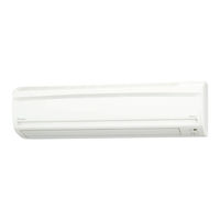
Daikin FTKS25DVM Service Manual (206 pages)
Inverter Multi F-Series
Brand:
Daikin
| Category:
Air Conditioner
| Size: 11 MB
Table of Contents
Table of Contents
3
Introduction
6
Safety Cautions
6
Used Icons
10
Part 1 List of Functions
12
Cooling Only
13
Heat Pump
15
Part 2 Specifications
18
Cooling Only
19
Indoor Units
19
Specifications
20
Outdoor Units
21
Heat Pump
22
Indoor Units
22
Outdoor Units
24
Part 3 Printed Circuit Board Connector Wiring Diagram
26
Printed Circuit Board Connector Wiring Diagram
27
Wall Mounted Type
27
Duct Connected Type
29
Outdoor Unit
31
Part 4 Function and Control
34
Main Functions
35
Frequency Principle
35
Power-Airflow Dual Flaps, Wide-Angle Louvers and Auto-Swing
37
Fan Speed Control for Indoor Units
38
Programme Dry Function
39
Automatic Operation
40
Thermostat Control
41
Night Set Mode
42
ECONO Mode
43
Intelligent Eye
44
HOME LEAVE Operation
46
Inverter POWERFUL Operation
47
Other Functions
48
Function of Thermistor
50
Heat Pump Model
50
Cooling Only Model
52
Control Specification
53
Mode Hierarchy
53
Frequency Control
54
Controls at Mode Changing / Start-Up
57
Compressor Protection Function
58
Discharge Pipe Temperature Control
59
Input Current Control
59
Freeze-Up Protection Control
60
Heating Peak-Cut Control
60
Fan Control
61
Liquid Compression Protection Function 2
61
Defrost Control
62
Electronic Expansion Valve Control
63
Malfunctions
67
Forced Operation Mode
68
Additional Function
69
Part 5 Operation Manual
70
System Configuration
71
Operation Instructions
71
Instruction
72
Manual Contents and Reference Page
72
Safety Precautions
73
Installation Site
74
Electrical Work
74
Names of Parts
75
Remote Control
77
Preparation before Operation
81
To Set the Clock
83
AUTO·DRY·COOL·HEAT·FAN Operation
84
To Change the Air Flow Rate Setting
85
Adjusting the Air Flow Direction
86
POWERFUL Operation
88
OUTDOOR UNIT QUIET Operation
89
ECONO Operation
90
HOME LEAVE Operation
91
MOLD PROOF Operation
93
INTELLIGENT EYE Operation
94
TIMER Operation
96
To Use on Timer Operation
97
To Combine on Timer and off Timer
97
Note for Multi System
98
Priority Room Setting
99
Care and Cleaning
100
Air Filter
101
Before a Long Idle Period
102
Cleaning the Air Filter
103
Troubleshooting
107
Check Again
108
Fault Diagnosis
110
Part 6 Service Diagnosis
112
Caution for Diagnosis
113
Problem Symptoms and Measures
115
Service Check Function
116
Check Method 1
116
Check Method 2
117
Troubleshooting
119
Error Codes and Description
119
Indoor Unit PCB Abnormality
120
Freeze-Up Protection Control or High Pressure Control
121
Fan Motor or Related Abnormality
123
Ac Motor
123
DC Motor
124
Thermistor or Related Abnormality (Indoor Unit)
126
Front Panel Open / Close Fault
127
Freeze-Up Protection Control
128
OL Activation (Compressor Overload)
130
Compressor Lock
131
DC Fan Lock
132
Input over Current Detection
133
Discharge Pipe Temperature Control
135
High Pressure Control in Cooling
136
Compressor Sensor System Abnormality
138
Position Sensor Abnormality
139
DC Voltage / DC Current Sensor Abnormality
141
Thermistor or Related Abnormality (Outdoor Unit)
142
Electrical Box Temperature Rise
144
Radiation Fin Temperature Rise
146
Output over Current Detection
148
Insufficient Gas
150
Over-Voltage Detection / Low-Voltage Detection
152
Anti-Icing Function in Other Rooms / Unspecified Voltage (between Indoor and Outdoor Units)
153
Voltage (between Indoor and Outdoor Units)
153
Outdoor Unit PCB Abnormality or Signal Transmission Circuit Abnormality
154
Check
157
How to Check
157
Four Way Valve Performance Check
159
Thermistor Resistance Check
160
Installation Condition Check
161
Discharge Pressure Check
162
Power Supply Waveforms Check
162
Capacitor Voltage Check
163
Inverter Units Refrigerant System Check
163
Power Transistor Check
164
Main Circuit Electrolytic Capacitor Check
164
Hall IC Check
165
Part 7 Removal Procedure
166
Outdoor Unit
167
Removal of the Panels and Plates
167
Removal of the Electrical Box
169
Removal of the PCB
174
Removal of the Sound Blanket
179
Removal of the Propeller Fan / Fan Motor
181
Removal of the Thermistors
184
Removal of the Compressor
186
Removal of the Four Way Valve • Electronic Expansion Valve
188
Part 8 Others
190
Others
191
Test Run from the Remote Control
191
Jumper Settings
192
Application of Silicon Grease to a Power Transistor and a Diode Bridge
193
Part 9 Appendix
194
Piping Diagrams
195
Indoor Units
195
Outdoor Units
196
Wiring Diagrams
197
Indoor Units
197
Outdoor Units
198
Index
200
Drawings & Flow Charts
204
Daikin FTKS25DVM Operation Manual (32 pages)
Brand:
Daikin
| Category:
Air Conditioner
| Size: 2 MB
Table of Contents
Table of Contents
2
Safety Precaution
3
Names of Parts
5
Preparation before Operation
8
DRY · COOL · FAN Operation
11
Adjusting the Air Flow Direction
13
POWERFUL Operation
15
OUTDOOR UNIT QUIET Operation
16
ECONO Operation
17
MOLD PROOF Operation
18
INTELLIGENT EYE Operation
19
TIMER Operation
21
Note for Multi System
23
Care
25
Care and Cleaning
25
Trouble Shooting
28
Daikin FTKS25DVM Service Manual (25 pages)
REMOVAL PROCEDURE, 2.0/2.5/3.5 kW Class, 9000/13000 Btu/h Class
Brand:
Daikin
| Category:
Air Conditioner
| Size: 2 MB
Table of Contents
Table of Contents
3
Air Filters
4
Front Panel
5
Front Grille
6
Horizontal Blades / Vertical Blade Assys
7
Electrical Box
9
Pcbs
11
Drain Pan Unit / Swing Motor
15
Fan Motor
17
Indoor Heat Exchanger
19
Fan Rotor
22
Advertisement
Related Products
Daikin FTKS25DVMW
Daikin FTKS25DVMW9
Daikin FTKS25DVMW(L)
Daikin FTKS25DVMT
Daikin FTKS25DVMA
Daikin FTKS25DAVMW(L)
Daikin FTKS25D3VMW(L)
Daikin FTKS25D2(3)VMW(L)
Daikin FTKS25D3VMW
Daikin FTKS25D2VMW
Daikin Categories
Air Conditioner
Heat Pump
Chiller
Remote Control
Air Handlers
More Daikin Manuals
Login
Sign In
OR
Sign in with Facebook
Sign in with Google
Upload manual
Upload from disk
Upload from URL