Advanced Energy Thyro-PX Series Power Manuals
Manuals and User Guides for Advanced Energy Thyro-PX Series Power. We have 2 Advanced Energy Thyro-PX Series Power manuals available for free PDF download: User Manual
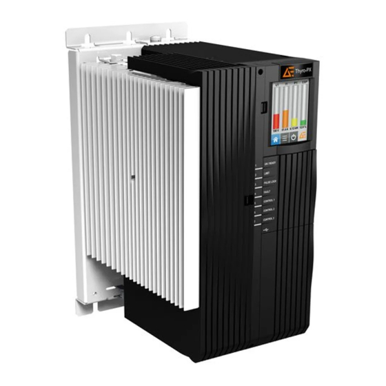
Advanced Energy Thyro-PX Series User Manual (109 pages)
Power Controller
Brand: Advanced Energy
|
Category: Controller
|
Size: 8 MB
Table of Contents
Advertisement
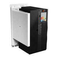
Advanced Energy Thyro-PX Series User Manual (93 pages)
Power controller
Brand: Advanced Energy
|
Category: Controller
|
Size: 4 MB
Table of Contents
Advertisement
Related Products
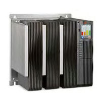
- Advanced Energy Thyro-PX
- Advanced Energy Thyro-PX Anybus PROFINET
- Advanced Energy THYRO-AX
- Advanced Energy Thyro-PX Anybus
- Advanced Energy Thyro-PX Anybus Modbus TCP
- Advanced Energy Thyro-Power Manager
- Advanced Energy Thyro-PX Electrical-Optical-Electrical Interface
- Advanced Energy Thyro-S
- Advanced Energy Thyro-A
- Advanced Energy ARTESYN Power Management Controller