Table of Contents
Advertisement
Quick Links
Advertisement
Table of Contents
Troubleshooting

Related Manuals for Advanced Energy Thyro-PX


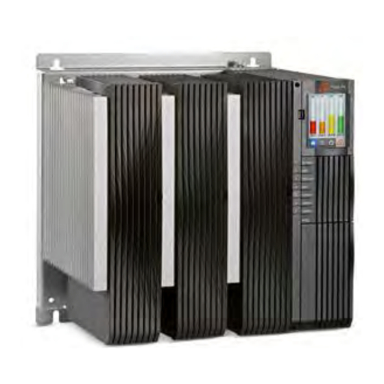
Summary of Contents for Advanced Energy Thyro-PX
- Page 1 ® Thyro-PX Power Controller User Manual 57010148-00B March 2016 ...
- Page 2 Advanced Energy Industries, Inc. shall not be liable in damages, of whatever kind, as a result of the reliance on or use of the information contained herein.
-
Page 3: Table Of Contents
® Advanced Energy Thyro-PX® Power Controller Table of Contents Chapter 1. Safety and Product Compliance Guidelines Important Safety Information ................. 1-1 Danger, Warning, and Caution Boxes .............. 1-1 Safety Guidelines .................... 1-2 Rules for Safe Installation and Operation ............ 1-2 Interpreting Product Labels ................... 1-2 Product Compliance .................... 1-4... - Page 4 ® Advanced Energy Thyro-PX® Power Controller Chapter 5. Installation, Setup, and Operation Preparing to Install the Unit ................... 5-1 Spacing Requirements ................... 5-1 Dimensional Drawings .................. 5-1 Installation Requirements ................ 5-14 Unpacking the Unit .................. 5-14 Lifting the Unit .................... 5-14 Installing the Unit .................... 5-15 Installing Optional Modules ................ 5-15...
- Page 5 ® Advanced Energy Thyro-PX® Power Controller No Load Current ..................... 6-3 Thyristors Are Set To Full Scale .............. 6-4 Other Malfunctions .................. 6-4 AE Global Services .................... 6-5 Returning Units for Repair .................. 6-5 57010148-00B Table of Contents...
- Page 6 Table 3-11. Environmental standard specifications ........... 3-11 Table 3-12. Climatic specifications .............. 3-12 Table 3-13. Type designation ................ 3-12 Table 4-1. Thyro-PX status LEDs ................. 4-3 Table 4-2. Relay indications .................. 4-4 Table 4-3. 9-pin digital I/O connector (X51) ............ 4-6 Table 4-4. 9-pin analog I/O connector (X52) ............ 4-7 Table 4-5.
- Page 7 Figure 4-6. Module slots .................. 4-12 Figure 4-7. Thyro‑Touch display ................ 4-13 Figure 5-1. Thyro-PX 1PX 500-16 H, 37 H, 75 H, 110 H ........ 5-2 Figure 5-2. Thyro-PX 1PX 500-130 H, 170 H, Thyro-PX 1PX 690-80 H .... 5-2 Figure 5-3. Thyro-PX 1PX 500-280 HF, Thyro-PX 1PX 690-200 HF .... 5-3 Figure 5-4.
- Page 8 ® Advanced Energy Thyro-PX® Power Controller Figure 5-32. TAKT waveform ................ 5-32 Figure 5-33. Start/stop ramp waveform ............... 5-32 Figure 5-34. VAR waveform ................ 5-33 Figure 5-35. Total setpoint .................. 5-34 Figure 5-36. Control characteristics for U control .......... 5-35 Figure 5-37. Shield clamp ................... 5-40...
-
Page 9: Chapter 1. Safety And Product Compliance Guidelines
Guidelines IMPORTANT SAFETY INFORMATION To ensure safe installation and operation of the Advanced Energy Thyro-PX unit, read and understand this manual before attempting to install and operate this unit. At a minimum, read and follow the safety guidelines, instructions, and practices. -
Page 10: Safety Guidelines
® Advanced Energy Thyro-PX® Power Controller CAUTION: CAUTION indicates a potentially hazardous situation that, if not avoided, could result in minor or moderate injury, and/or property damage. CAUTION is also used for property-damage-only accidents. ATTENTION: ATTENTION indique une situation potentiellement dangereuse qui, si elle n’est pas évitée, pourrait provoquer des blessures mineures ou modérées et/... - Page 11 ® Advanced Energy Thyro-PX® Power Controller CE label Complies with applicable European directives. Protective conductor terminal This terminal must be connected first and be of proper type and size for the circuit with the highest voltage and current carrying capacity. Note that other...
-
Page 12: Product Compliance
® Advanced Energy Thyro-PX® Power Controller Electrocution hazard Heavy object—can cause muscle strain or back injury Heavy object—do not lift manually Electrical fuse Alternating current Direct current ® Listed to Canadian and United States safety standards UL Listed to United States safety... -
Page 13: Safety And Emc Directives And Standards
® Advanced Energy Thyro-PX® Power Controller Safety and EMC Directives and Standards For information concerning compliance to applicable EU requirements, refer to the EU Declaration of Conformity for this unit. The Declaration of Conformity may also include a supplementary section covering compliance to non-EU regulatory requirements and/or industry standards or guidelines. -
Page 14: Interlocks And Limiting Conditions
Les produits Advanced Energy comprennent des dispositifs de verrouillage uniquement si la spécification du produit l’exige. Les dispositifs de verrouillage d’Advanced Energy ne sont pas destinés à satisfaire aux normes de sécurité ni à s’y conformer. Lorsqu’un système comprend un dispositif de verrouillage, vous demeurez responsable de satisfaire aux normes de sécurité... -
Page 15: Chapter 2. Product Overview
• Serving as primary power controller for a transformer with subsequent load Due to use of high quality thyristors, the Thyro-PX power controller has a type range up to 2900 A, and the nominal design loads reach up to ~ 2860 kW. -
Page 16: Analog And Digital I/O
® Advanced Energy Thyro-PX® Power Controller ◦ Resistive and inductive loads ◦ External 90 VAC to 265 VAC or 24 VDC auxiliary power supply • Useful features ◦ Resistive load and transformer load ◦ Soft start function for transformer load ◦... -
Page 17: Chapter 3. Specifications
Thyro-PX® Power Controller Chapter Specifications PHYSICAL SPECIFICATIONS Table 3‑1. Physical specifications Description Specification General Physical Specifications Size For 500 V units, see Table 3-2 Weight For 690 V units, see Table 3-3 Mounting Mechanical Mounting hardware not included... -
Page 18: Table 3-2. Type Range 500 Volts
Figure 5-6 2900 HF 593 (23.3) 577 (22.7) 473 (18.6) 62 (136.7) Figure 5-7 Thyro-PX 2PX, Thyro-PX 1P ... VSC2 16 H, 37 H, 75 H, 110 H 225 (8.9) 320 (12.6) 232 (9.1) 10 (22.0) Figure 5-8 130 H, 170H 325 (12.8) -
Page 19: Table 3-3. Type Range 690 Volts
445 (17.5) 50 (110.2) Figure 5-6 2600 HF 593 (23.3) 577 (22.7) 473 (18.6) 62 (136.7) Figure 5-7 Thyro-PX 2PX, Thyro-PX 1PX ... VSC2 80 H 325 (12.8) 320 (12.6) 232 (9.1) 12 (26.5) Figure 5-9 200 HF 325 (12.8) 415 (16.3... -
Page 20: Electrical Specifications
® Advanced Energy Thyro-PX® Power Controller ELECTRICAL SPECIFICATIONS Table 3‑4. Electrical specifications Description Specification Electrical Requirements AC input line voltage Type voltage 500 V units: 184 V to 550 V Type voltage 690 V units: 400 V to 759 V... -
Page 21: Table 3-5. Type Voltage 500 Volts
® Advanced Energy Thyro-PX® Power Controller Table 3‑4. Electrical specifications (Continued) Description Specification Precision U-control: Better than ± 0.5% I-control: Better than ± 0.5% P-control: Better than ± 1% All specifications are relating to the respective final value. Limitations Voltage limitation U... - Page 22 ® Advanced Energy Thyro-PX® Power Controller Table 3‑5. Type Voltage 500 Volts (Continued) Model Current Type Power Dissipation Burden Fuse F1 Type Current Transformer (kVA) R (Ω) Thyro-PX 2PX 16 H 400/1 27.4 37 H 100/1 2.70 75 H 100/1 1.30...
- Page 23 Table 3‑6. Type Voltage 500 Volts ... Voltage Sequence Control (VSC) Model Type Power Dissipation Current Burden R Fuse F1 (A) (kVA) Transformer (Ω) Type Current Thyro-PX 1PX ... VSC2 16 H 400/1 27.4 37 H 100/1 2.70 75 H 100/1 1.30 110 H 100/1 0.91...
-
Page 24: Table 3-7. Type Voltage 690 Volts
® Advanced Energy Thyro-PX® Power Controller Table 3‑7. Type Voltage 690 Volts Model Type Power Dissipation Current Burden R Fuse F1 (A) (kVA) Transformer (Ω) Type Current Thyro-PX 1PX 80 H 100/1 200 HF 200/1 300 HF 300/1 500 HF... -
Page 25: Cooling Specifications
3000/1 4x1400 COOLING SPECIFICATIONS Type H Thyro-PX power controllers are self cooled, while type HF units are force cooled. The fan in HF units require a separate power source at 230 V, 50/60 Hz. Table 3‑9. Current derating ... -
Page 26: Table 3-10. Fan Current, Air Volume, And Sound Pressure
® Advanced Energy Thyro-PX® Power Controller Table 3‑9. Current derating (Continued) Air Temperature RATED CURRENT Self Cooling Forced Cooling 45°C (113°F) 1.00 0.91 50°C (122°F) 0.95 0.87 55°C (131°F) 0.88 0.81 UL applications limited to +40°C (104°F) Rating Self cooling Forced cooling Temperature (°C) -
Page 27: Environmental Specifications
(50°F), a longer fan startup time is required. Therefore, the overcurrent protection device should be rated at twice the specified continuous current. ENVIRONMENTAL SPECIFICATIONS The two following tables describe the environmental specifications for the Thyro-PX unit. Table 3‑11. Environmental standard specifications ... -
Page 28: Type Designation
Maximum absolute humidity when the unit temperature directly decreases from +70°C to +15°C (+158°F to +59°F) TYPE DESIGNATION The type designations of the Thyro-PX power controllers are derived from the construction of its power section, as shown in the following table. Table 3‑13. Type designation ... - Page 29 ® Advanced Energy Thyro-PX® Power Controller Table 3‑13. Type designation (Continued) Type Range Designation Features 2-phase power section used with a 3-phase load in 3-phase economic circuit (not for phase-angle firing VAR), or with two 1-phase loads in multi-zone mode...
-
Page 30: Chapter 4. Communication Controls
The unit can be configured using either the Thyro-Touch display, or via the Thyro- Tool Pro PC software. The setpoint control characteristic of Thyro-PX may be easily adapted for the control output signal of the upstream process controller or automation system. The adaptation is made by changing the starting and ending points of the control characteristic. -
Page 31: Status Indicators (Leds)
Pulse Lock On/Off (without acknowledgement), or Regulator Lock On/Off (without acknowledgement) configuration to require that pulse shutdown occur. The Thyro-PX unit LED status indicators are located on the front panel of the unit. ☞ Important This manual describes the default configuration. Though these functions are fully configurable, AE recommends not changing the default configuration. -
Page 32: Table 4-1. Thyro-Px Status Leds
® Advanced Energy Thyro-PX® Power Controller Figure 4‑2. Status LEDs Table 4‑1. Thyro-PX status LEDs Status ON/READY Green: On, ready for operation Red: Severe hardware fault. (EEPROM fault) Red blinking: Hardware configuration incorrect. Orange blinking: Firmware is being updated. -
Page 33: Relay Indicators
Lock On/Off (without acknowledgement) configuration to require that pulse shutdown occur. The Thyro-PX power controller is fitted with three relays. Each of these relays has a change-over contact. AE recommends that users keep the default settings for K1 and K2. Each relay can be reconfigured as normally-open or normally-closed using the Thyro-Touch display or the Thyro-Tool Pro PC software. -
Page 34: Analog And Digital I/O
® Advanced Energy Thyro-PX® Power Controller Table 4‑2. Relay indications (Continued) Relay Name Description Optional relay The function of this relay is customer-configured. It is possible to implement functions like a follow-up relay for ventilator control, or to bypass the fault relay at system startup. K3 can also be used as an additional fault relay or limiting relay, by re-parameterization. -
Page 35: Table 4-3. 9-Pin Digital I/O Connector (X51)
® Advanced Energy Thyro-PX® Power Controller X10 RS-232 X6 μUSB X51 Digital I/O X53 Analog/Digital I/O (optional) or Digital I/O (optional) X54 Analog/Digital I/O (optional) or Digital I/O (optional) X52 Analog I/O Figure 4‑4. Front I/O connectors Table 4‑3. 9-pin digital I/O connector (X51) ... -
Page 36: Table 4-4. 9-Pin Analog I/O Connector (X52)
® Advanced Energy Thyro-PX® Power Controller Table 4‑4. 9-pin analog I/O connector (X52) Signal Name Function X52.1 + 5 V X52.2 Analog input 1.1 Setpoint power controller 1 X52.3 Analog input 1.2 Setpoint power controller 2 X52.4 Analog input 1.3 Setpoint power controller 3 X52.5... - Page 37 ® Advanced Energy Thyro-PX® Power Controller Table 4‑6. 16-pin digital I/O connector (X53 or X54) (Continued) Signal Name Function X54.3 Digital input 3.1 User configured X54.4 Digital input 3.2 User configured X54.5 Digital input 3.3 User configured X54.6 Digital input 3.4 User configured X54.7...
-
Page 38: Table 4-7. Relay K1, K2, And K3 Connectors (X21, X22, X23)
® Advanced Energy Thyro-PX® Power Controller I/O bus 24 V auxiliary power supply input Fault relay K1 Limit relay K2 Optional relay K3 AC auxiliary power supply input Figure 4‑5. Bottom I/O connectors Table 4‑7. Relay K1, K2, and K3 connectors (X21, X22, X23) ... -
Page 39: Module Slots
The unit has two module slots. The Anybus module slot may be equipped with one of the following Anybus modules to add field bus communication capability to the Thyro-PX power controller. For additional module documentation, scan the QR code in the table below. - Page 40 ® Advanced Energy Thyro-PX® Power Controller Table 4‑10. Module documentation links (Continued) Anybus Module Link QR Code ™ http://aei.com/en/ Anybus EtherNet/IP anybus_ethernet_ip.html http://aei.com/en/ ® Anybus EtherCAT anybus_ethercat.html ® http://aei.com/en/ Anybus Modbus anybus_modbus_tcp.html Anybus Modbus RTU http://aei.com/en/ anybus_modbus_rtu.html The second module slot may be equipped with the dASM module. All modules are optional.
-
Page 41: Thyro-Touch Display
® Advanced Energy Thyro-PX® Power Controller Anybus module dASM module Figure 4‑6. Module slots THYRO‑TOUCH DISPLAY The Thyro-Touch display is an optional accessory for the parameterization and visualization of measured values, such as current, voltage, power, and setpoint. 57010148-00B Communication Controls... -
Page 42: Figure 4-7. Thyro-Touch Display
Thyro-PX® Power Controller Figure 4‑7. Thyro‑Touch display In addition to simplifying the handling of the Thyro-PX power controller, the Thyro-Touch display also offers a quick overview of power controller status. Ongoing data can also be displayed as line or bar charts. The integrated data recorder enables a long-term recording of up to six measured values, including status messages. -
Page 43: Thyro-Touch Display Menus
® Advanced Energy Thyro-PX® Power Controller • The display can either be connected directly to the power controller, or connected remotely with the cabinet installation kit (SEK). • Additional Bluetooth Low Energy communication between the power controller ® ™ and free Thyro-App for iOS... -
Page 44: Software User Interface
® Advanced Energy Thyro-PX® Power Controller SOFTWARE USER INTERFACE The optional Thyro-Tool Pro PC software is available for commissioning and visualization. This software can be used to: • Set and display parameters • Display current operating conditions and events •... -
Page 45: Chapter 5. Installation, Setup, And Operation
• Units may be installed side-by-side with no intervening distance. • Ensure that the unit is not exposed to sources of heat. Dimensional Drawings The following figures show Thyro-PX unit dimensions, front, and side views. 57010148-00B Installation, Setup, and Operation 5‑1... -
Page 46: Figure 5-1. Thyro-Px 1Px 500-16 H, 37 H, 75 H, 110 H
® Advanced Energy Thyro-PX® Power Controller Figure 5‑1. Thyro-PX 1PX 500-16 H, 37 H, 75 H, 110 H Figure 5‑2. Thyro-PX 1PX 500-130 H, 170 H, Thyro-PX 1PX 690-80 H 57010148-00B Installation, Setup, and Operation 5‑2... -
Page 47: Figure 5-3. Thyro-Px 1Px 500-280 Hf, Thyro-Px 1Px 690-200 Hf
® Advanced Energy Thyro-PX® Power Controller Figure 5‑3. Thyro-PX 1PX 500-280 HF, Thyro-PX 1PX 690-200 HF Figure 5‑4. Thyro-PX 1PX 500-350 HF, 495 HF, 650 HF, Thyro-PX 1PX 690-300 HF, 500 HF 57010148-00B Installation, Setup, and Operation 5‑3... -
Page 48: Figure 5-5. Thyro-Px 1Px 500-1000 Hf, 1500 Hf, Thyro-Px 1Px 690-780
® Advanced Energy Thyro-PX® Power Controller Figure 5‑5. Thyro-PX 1PX 500-1000 HF, 1500 HF, Thyro-PX 1PX 690-780 HF, 1400 HF Figure 5‑6. Thyro-PX 1PX 500-2100 HF, Thyro-PX 1PX 690-2000 HF 57010148-00B Installation, Setup, and Operation 5‑4... -
Page 49: Figure 5-7. Thyro-Px 1Px 500-2900Hf, Thyro-Px 1Px 690-2600 Hf
395 mm (3.9") (15.5") 350 mm 35 mm 522 mm (13.8") (1.4") (20.5") 473 mm (18.6) Figure 5‑7. Thyro-PX 1PX 500-2900HF, Thyro-PX 1PX 690-2600 HF Figure 5‑8. Thyro-PX 2PX 500-16 H, 37 H, 75 H, 110 H 57010148-00B Installation, Setup, and Operation 5‑5... -
Page 50: Figure 5-9. Thyro-Px 2Px 500-130 H, 170 H, Thyro-Px 2Px 690-80 H
® Advanced Energy Thyro-PX® Power Controller Figure 5‑9. Thyro-PX 2PX 500-130 H, 170 H, Thyro-PX 2PX 690-80 H Figure 5‑10. Thyro-PX 2PX 500-280 HF, Thyro-PX 2PX 690-200 HF 57010148-00B Installation, Setup, and Operation 5‑6... -
Page 51: Figure 5-11. Thyro-Px 2Px 500-350Hf, 495 Hf, 650 Hf, Thyro-Px 2Px
® Advanced Energy Thyro-PX® Power Controller Figure 5‑11. Thyro-PX 2PX 500-350HF, 495 HF, 650 HF, Thyro-PX 2PX 690-300 HF, 500 HF Figure 5‑12. Thyro-PX 2PX 500-1000 HF, 1500 HF, Thyro-PX 2PX 690-780 HF, 1400 HF 57010148-00B Installation, Setup, and Operation 5‑7... -
Page 52: Figure 5-13. Thyro-Px 2Px 500-2000 Hf, Thyro-Px 2Px 690-1850 Hf
® Advanced Energy Thyro-PX® Power Controller Figure 5‑13. Thyro-PX 2PX 500-2000 HF, Thyro-PX 2PX 690-1850 HF Figure 5‑14. Thyro-PX 2PX 500-2750 HF, Thyro-PX 2PX 690-2400 HF 57010148-00B Installation, Setup, and Operation 5‑8... -
Page 53: Figure 5-15. Thyro-Px 3Px 500-16 H, 37 H, 75 H, 110 H
® Advanced Energy Thyro-PX® Power Controller Figure 5‑15. Thyro-PX 3PX 500-16 H, 37 H, 75 H, 110 H Figure 5‑16. Thyro-PX 3PX 500-130 H, 170 H, Thyro-PX 3PX 690-80 H 57010148-00B Installation, Setup, and Operation 5‑9... -
Page 54: Figure 5-17. Thyro-Px 3Px 500-280 Hf, Thyro-Px 3Px 690-200 Hf
® Advanced Energy Thyro-PX® Power Controller Figure 5‑17. Thyro-PX 3PX 500-280 HF, Thyro-PX 3PX 690-200 HF 57010148-00B Installation, Setup, and Operation 5‑10... -
Page 55: Figure 5-18. Thyro-Px 3Px 500-350Hf, 495 Hf, 650 Hf, Thyro-Px 3Px
® Advanced Energy Thyro-PX® Power Controller Figure 5‑18. Thyro-PX 3PX 500-350HF, 495 HF, 650 HF, Thyro-PX 3PX 690-300 HF, 500 HF 57010148-00B Installation, Setup, and Operation 5‑11... -
Page 56: Figure 5-19. Thyro-Px 3Px 500-1000 Hf, 1500 Hf, Thyro-Px 3Px 690-780
® Advanced Energy Thyro-PX® Power Controller Figure 5‑19. Thyro-PX 3PX 500-1000 HF, 1500 HF, Thyro-PX 3PX 690-780 HF, 1400 HF 57010148-00B Installation, Setup, and Operation 5‑12... -
Page 57: Figure 5-20. Thyro-Px 3Px 500-2000 Hf, Thyro-Px 3Px 690-1700 Hf
® Advanced Energy Thyro-PX® Power Controller Figure 5‑20. Thyro-PX 3PX 500-2000 HF, Thyro-PX 3PX 690-1700 HF Figure 5‑21. Thyro-PX 3PX 500-2600 HF, Thyro-PX 3PX 690-2200 HF 57010148-00B Installation, Setup, and Operation 5‑13... -
Page 58: Installation Requirements
1. Unpack and inspect the unit carefully, looking for obvious physical damage. 2. If no damage is apparent, proceed with the unit installation and setup. 3. If you do see signs of shipping damage, contact Advanced Energy and the carrier immediately. -
Page 59: Installing The Unit
® Advanced Energy Thyro-PX® Power Controller CAUTION: The modules are heavy. Use two people to lift the module. ATTENTION: Les modules sont lourds. Le module doit être soulevé par deux personnes. TO LIFT THE UNIT • Lift the unit by holding on to the front of the unit while also supporting the rear of the unit. - Page 60 ® Advanced Energy Thyro-PX® Power Controller Table 5‑1. Module documentation links Anybus Module Link QR Code Anybus PROFIBUS http://aei.com/en/ DPV1 anybus_profibus.html Anybus PROFINET http://aei.com/en/ anybus_profinet.html Anybus DeviceNet http://aei.com/en/ anybus_devicenet.html Anybus EtherNet/IP http://aei.com/en/ anybus_ethernet_ip.html Anybus EtherCAT http://aei.com/en/ anybus_ethercat.html Anybus Modbus TCP http://aei.com/en/...
-
Page 61: Figure 5-22. Anybus Module Removal
® Advanced Energy Thyro-PX® Power Controller Table 5‑1. Module documentation links (Continued) Anybus Module Link QR Code Anybus Modbus RTU http://aei.com/en/ anybus_modbus_rtu.html If an Anybus module must be removed from the unit, loosen the TORX T8 mounting screws 3 turns, and pry out the module with a small flat-bladed screwdriver, as shown in the following figure. -
Page 62: Configuring As A Multi-Zone Controller
® Advanced Energy Thyro-PX® Power Controller Figure 5‑23. I/O module removal Configuring as a Multi-Zone Controller DANGER: RISK OF DEATH OR BODILY INJURY. Disconnect and lockout/tagout all sources of input power before working on this unit or anything connected to ... - Page 63 A 2-phase or 3-phase Thyro-PX power controller can be configured to operate as a 1- phase unit controlling two or three zones. 1. Remove the covers from the unit at an ESD safe work space.
-
Page 64: Figure 5-24. Configure 3-Phase As Multi-Zone
® Advanced Energy Thyro-PX® Power Controller Figure 5‑24. Configure 3-phase as multi-zone 57010148-00B Installation, Setup, and Operation 5‑20... -
Page 65: Figure 5-25. Configure 2-Phase As Multi-Zone
® Advanced Energy Thyro-PX® Power Controller Figure 5‑25. Configure 2-phase as multi-zone 57010148-00B Installation, Setup, and Operation 5‑21... -
Page 66: Mounting The Unit
® Advanced Energy Thyro-PX® Power Controller Mounting the Unit 1. Install the unit on or in the mounting surface, rack, or cabinet. 2. Fasten the unit to the mounting surface, rack, or cabinet. Use suitable fasteners. “Dimensional Drawings” on page 5-1 for mounting hole details. -
Page 67: Connecting Load And Auxiliary Power
® Advanced Energy Thyro-PX® Power Controller Shield clamp Cable Exposed shield Figure 5‑26. Shield clamp The following signals are always required for operation of the device: SETPOINT, PULSE LOCK. ☞ Important By default, the unit is configured to require a customer supplied PULSE LOCK jumper. -
Page 68: Table 5-2. Terminal Screw Size
® Advanced Energy Thyro-PX® Power Controller WARNING: This device must be installed so that the output power connection is inaccessible to the user. AVERTISSEMENT: Le dispositif doit être installé de façon à ce que l’utilisateur ne puisse accéder à... -
Page 69: Connection Diagrams
® Advanced Energy Thyro-PX® Power Controller Table 5‑2. Terminal screw size (Continued) Model Connector Protective Screw Earth screw 80 H 110 H 130 H, 170 H 200 HF, 280 HF, 300 HF 495 HF, 500 HF, 650 HF 780 HF, 1000 HF, 1400 HF, 1500 HF, 1700 HF,... -
Page 70: Figure 5-27. 1Px Power Controller Connections
® Advanced Energy Thyro-PX® Power Controller Figure 5‑27. 1PX power controller connections 57010148-00B Installation, Setup, and Operation 5‑26... -
Page 71: Figure 5-28. 2Px Power Controller Connections
® Advanced Energy Thyro-PX® Power Controller Figure 5‑28. 2PX power controller connections 57010148-00B Installation, Setup, and Operation 5‑27... -
Page 72: Figure 5-29. 3Px Power Controller Connections
® Advanced Energy Thyro-PX® Power Controller Figure 5‑29. 3PX power controller connections 57010148-00B Installation, Setup, and Operation 5‑28... -
Page 73: Figure 5-30. 1Px Vsc 2 Power Controller Connections
® Advanced Energy Thyro-PX® Power Controller Figure 5‑30. 1PX VSC 2 power controller connections 57010148-00B Installation, Setup, and Operation 5‑29... -
Page 74: Figure 5-31. 1Px Vsc 3 Power Controller Connections
® Advanced Energy Thyro-PX® Power Controller Figure 5‑31. 1PX VSC 3 power controller connections 57010148-00B Installation, Setup, and Operation 5‑30... -
Page 75: First Time Operation
6. Verify that the FAULT LED is not lit. 7. Verify that an increase in setpoint applies power to the load. If the Thyro-PX unit is delivering power and the LIMIT LED is not lit, the unit is functioning properly. -
Page 76: Operating Modes
® Advanced Energy Thyro-PX® Power Controller you have issues or problems operating your unit after you have followed the first time operation guidelines. ® You can monitor your unit with a system (user-supplied) controller or a Windows based personal computer running Thyro-Tool Pro PC. To order this software, contact your AE sales representative. -
Page 77: Phase-Angle Firing (Var)
Figure 5‑34. VAR waveform STARTING MODES The Thyro-PX power controller has enhanced starting modes that are used with special loads. These modes are used when the unit is started or restarted, and the restart behavior can be configured. RAMP Starting Mode This starting mode begins with a specially configured, one-time block, normally in the form of a ramp (default). -
Page 78: Table 5-4. Setpoint Characteristics
® Advanced Energy Thyro-PX® Power Controller Analog setpoint Addition Local Bus setpoint Motor potentiometer Total setpoint Setpoint configuration Analog setpoint Addition Remote/local switch Bus setpoint Remote Motor potentiometer Setpoint configuration Figure 5‑35. Total setpoint The local analog setpoint, and local motor potentiometer setpoint are used by default. -
Page 79: Control Types
Figure 5‑36. Control characteristics for U control CONTROL TYPES The Thyro-PX power controller has six control types effective as underlying controls. Mains voltage variations and load changes are directly, and therefore quickly, adjusted by bypassing the slow temperature control system. -
Page 80: Controller Response
® Advanced Energy Thyro-PX® Power Controller Table 5‑5. Controlled values (Continued) Control Type Control Value (Proportional to the total setpoint) control Output current, I No regulation Output proportional to the setpoint Controller Response If the load resistance changes (for example, due to temperature effect, aging, or load fault), the power controller responds as shown in the following table. -
Page 81: Minimum And Maximum Monitoring
® Advanced Energy Thyro-PX® Power Controller occurred warnings or errors are shown in the status line of the Thyro-Touch display. Select a status line to retrieve the corresponding warning or error message. Minimum and Maximum Monitoring The following table shows the minimum and maximum conditions that can be monitored using the Thyro-Tool Pro PC software. -
Page 82: Fan Monitoring
The digital and dynamic dASM process offers the option of dynamic mains load optimization when multiple Thyro-PX power controllers operate in the TAKT mode. For systems in which there are multiple power controllers, individual power controllers are synchronized so that a regular mains load is achieved. This avoids random load peaks caused by multiple power controllers switching on at the same time. -
Page 83: Dasm Application Considerations
® Advanced Energy Thyro-PX® Power Controller lower load, which results in savings in investment and operating costs, and much smaller system perturbations. dASM can be applied whenever multiple power controllers operate together on a common grid supply in the TAKT mode. Other features include: •... -
Page 84: Dasm Commissioning
® Advanced Energy Thyro-PX® Power Controller Shield clamp Cable Exposed shield Figure 5‑37. Shield clamp dASM Commissioning To ensure optimal functionality of the dASM grid load optimization, make sure to do the following when commissioning: • Check the power controller for in-phase grid connection •... -
Page 85: Errors In Dasm Communication
® Advanced Energy Thyro-PX® Power Controller Errors in dASM Communication If the dASM communication between units is interrupted, then a new master is automatically generated in the system beyond the point of interruption. Notification: dASM device number is incorrect. For example, if a cable break causes an interruption between unit 6 and unit 7, the dASM system continues to run, and unit 1 now operates as a master only for units 1 to 6 and displays that an incorrect number of units are present in the dASM network. -
Page 86: Chapter 6. Troubleshooting And Global Services
Thyro-PX® Power Controller Chapter Troubleshooting and Global Services Before calling AE Global Services, perform recommended checks and troubleshooting procedures. If you are still unable to resolve the issue and resume normal operation after following these checks and procedures, contact AE Global Services. -
Page 87: Troubleshooting Unit Output
® Advanced Energy Thyro-PX® Power Controller Troubleshooting Action Check Is the green ON/ If no: The auxiliary 230 VAC or 24 VDC supply is faulty. READY LED lit? Is the red ON/ If yes: There is an EEPROM fault. READY LED lit? Is the red ON/ If yes: The hardware configuration is incorrect. -
Page 88: No Leds Lit
® Advanced Energy Thyro-PX® Power Controller DANGER: RISQUE DE MORT OU DE BLESSURES CORPORELLES. Débrancher et verrouiller/étiqueter toutes les sources de puissance d’entrée avant de travailler sur cette unité ou sur tout élément qui y est raccordé. DANGER: Personnel must receive proper training before installing or troubleshooting high-energy electrical equipment. -
Page 89: Thyristors Are Set To Full Scale
® Advanced Energy Thyro-PX® Power Controller ◦ Parameterization of the setpoint inputs 20 mA, 5 V, 10 V, is matched to output of the temperature controller. ◦ Parameters of the control characteristic of the respective analog input are correct. • Parameters Iemax, Uemax, and Pmax are set too small. -
Page 90: Ae Global Services
mailto:powercontroller@aei.com +49 (0)2902 763-520 If you would prefer to contact a local or regional sales or service office, visit the Advanced Energy website for current contact information: • http://www.advanced-energy.com RETURNING UNITS FOR REPAIR ... - Page 91 ® Advanced Energy Thyro-PX® Power Controller number of the unit as well as the reason for the proposed return. This consultation call will allow Global Services to determine if the unit must actually be returned for the problem to be corrected. Such technical consultation is always available at no charge.
- Page 92 ® Advanced Energy Thyro-PX® Power Controller Index AE customer services contact information 6‑5 icons authorized returns 6‑5 in user manual 1‑1 on unit 1‑2 industry guidelines, compliance with 1‑5 installation certification 1‑4 connecting I/O 5‑22 communication 4‑5, 4‑10 connecting the load 5‑23 compliance grounding 5‑22...
- Page 93 ® Advanced Energy Thyro-PX® Power Controller mounting 5‑22 relays 4‑4 multi-zone configuration 5‑18 symbols in user manual 1‑1 on unit 1‑2 normal operation 5‑31 touch display accessing the main menu 4‑14 operation features 4‑12 control types 5‑35 menus 4‑14 first time 5‑31 troubleshooting monitoring 5‑36...
Need help?
Do you have a question about the Thyro-PX and is the answer not in the manual?
Questions and answers