Table of Contents
Advertisement
Quick Links
Advertisement
Table of Contents
Troubleshooting

Related Manuals for Advanced Energy Thyro-PX Series


Summary of Contents for Advanced Energy Thyro-PX Series
- Page 1 ® Thyro-PX Power Controller User Manual 57010148-00G April 2020 ...
- Page 2 No part of this manual may be reproduced or copied without the express written permission of Advanced Energy Industries, Inc. Any unauthorized use of this manual or its contents is strictly prohibited. Copyright © 2016 - 2020 Advanced Energy Industries, Inc. All Rights Reserved.
- Page 3 EN ÉCHEC OU CONTOURNER LES DISPOSITIFS DE PROTECTION DE VERROUILLAGE OU DE MISE À LA TERRE. TRADEMARKS All Advanced Energy trademarks are the property of Advanced Energy Industries, Inc. For the list of Advanced Energy trademarks, visit: http://www.advanced- energy.com/en/Trademarks.html. Any unauthorized use of Advanced Energy trademarks is prohibited.
-
Page 4: Table Of Contents
® ® Advanced Energy Thyro-PX Power Controller Table of Contents Chapter 1. Safety and Product Compliance Guidelines Important Safety Information ................. 1-1 Danger, Warning, and Caution Boxes .............. 1-1 Safety Guidelines .................... 1-2 Rules for Safe Installation and Operation ............ 1-2 Interpreting Product Labels ................ - Page 5 ® ® Advanced Energy Thyro-PX Power Controller Manage Devices and Files .............. 4-16 Parameters .................... 4-17 Chapter 5. Installation, Setup, and Operation Preparing to Install the Unit ................... 5-1 Spacing Requirements ................... 5-1 Dimensional Drawings .................. 5-1 Installation Requirements ................ 5-14 Unpacking the Unit ..................
- Page 6 ® ® Advanced Energy Thyro-PX Power Controller Troubleshooting Checklist .................. 6-1 Troubleshooting Unit Output ................. 6-2 No LEDs Lit .................... 6-3 No Load Current ..................... 6-3 Thyristors Are Set To Full Scale .............. 6-4 Other Malfunctions .................. 6-4 AE Global Services .................... 6-5 Primary Contact Information ................ 6-5...
- Page 7 ® ® Advanced Energy Thyro-PX Power Controller List of Tables Table 1-1. Transient surge suppression device ratings ........ 1-6 Table 1-2. Interlocks and limiting conditions ............ 1-8 Table 3-1. Physical specifications ................. 3-1 Table 3-2. Type Range 500 Volts ................. 3-2 Table 3-3.
- Page 8 ® ® Advanced Energy Thyro-PX Power Controller List of Figures Figure 3-1. Current derating .................. 3-9 Figure 4-1. Total setpoint .................. 4-2 Figure 4-2. Status LEDs .................. 4-3 Figure 4-3. Shield clamp .................. 4-5 Figure 4-4. Front I/O connectors ................ 4-6 Figure 4-5. Bottom I/O connectors ................ 4-9 Figure 4-6.
- Page 9 ® ® Advanced Energy Thyro-PX Power Controller Figure 5-20. Thyro-PX 3PX 500-1850 HF, Thyro-PX 3PX 690-1700 HF .... 5-13 Figure 5-21. Thyro-PX 3PX 500-2600 HF, Thyro-PX 3PX 690-2200 HF .... 5-13 Figure 5-22. Anybus module removal .............. 5-17 Figure 5-23. I/O module removal ................ 5-17 Figure 5-24.
-
Page 10: Chapter 1. Safety And Product Compliance Guidelines
Guidelines IMPORTANT SAFETY INFORMATION To ensure safe installation and operation of the Advanced Energy Thyro-PX unit, read and understand this manual before attempting to install and operate this unit. At a minimum, read and follow the safety guidelines, instructions, and practices. -
Page 11: Safety Guidelines
® ® Advanced Energy Thyro-PX Power Controller CAUTION: CAUTION indicates a potentially hazardous situation that, if not avoided, could result in minor or moderate injury, and/or property damage. CAUTION is also used for property-damage-only accidents. ATTENTION: ATTENTION indique une situation potentiellement dangereuse qui, si elle n’est pas évitée, pourrait provoquer des blessures mineures ou modérées... - Page 12 ® ® Advanced Energy Thyro-PX Power Controller Complies with applicable European directives. Protective conductor terminal This terminal must be connected first and be of proper type and size for the circuit with the highest voltage and current carrying capacity. Note that other...
-
Page 13: Product Compliance
® ® Advanced Energy Thyro-PX Power Controller Short-circuit protected Environmentally Friendly Use Period of 25 years per China RoHS—recycle responsibly at end of life Electrocution hazard Heavy object—can cause muscle strain or back injury Heavy object—do not lift manually Electrical fuse... -
Page 14: Safety And Emc Directives And Standards
® ® Advanced Energy Thyro-PX Power Controller For more information, refer to the Certificate or Letter of Conformity (US) or Declaration of Conformity (EU), available on request. • CE Marking – Self-declaration, assessed by AE Corporate Compliance • EMC measurements – Verified by AE Corporate Compliance •... -
Page 15: Environmental Compliance
® ® Advanced Energy Thyro-PX Power Controller • Use 60°C/75°C copper conductors for control circuits only. • The maximum surrounding air temperature under UL conditions is 40°C (104°F). • The unit is suitable for use on a circuit capable of delivering not more than 100 kA rms symmetrical amperes, xxx volts maximum, when protected by RK5 class fuses, where xxx is the maximum rated voltage of the unit. -
Page 16: Interlocks And Limiting Conditions
• EU REACH – European Union Regulation (EC) No. 1907/2006 Registration, Evaluation, Authorization and Restriction of Chemicals Advanced Energy manufactures articles subject to Article 33 of REACH and, upon request, will provide information regarding Substances of Very High Concern (SVHC) currently identified by the European Chemical Agency (ECHA) that are contained in this product, at concentrations greater than 0.1%... -
Page 17: Table 1-2. Interlocks And Limiting Conditions
Les produits Advanced Energy comprennent des dispositifs de verrouillage uniquement si la spécification du produit l’exige. Les dispositifs de verrouillage d’Advanced Energy ne sont pas destinés à satisfaire aux normes de sécurité ni à s’y conformer. Lorsqu’un système comprend un dispositif de verrouillage, vous demeurez responsable de satisfaire aux normes de sécurité... -
Page 18: Chapter 2. Product Overview
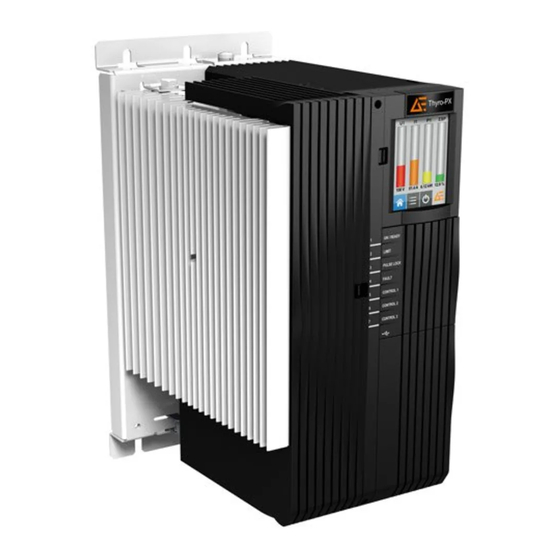
® Thyro-PX Power Controller Chapter Product Overview GENERAL DESCRIPTION The Thyro-PX is a communication-enabled SCR power controller. The Thyro-PX power controller can be installed where voltages, currents, or power have to be controlled precisely in 1-phase or 3-phase networks. Several modes of operation and control, good coupling ability to process and automation technology, high control precision by application of a 32 bit processor, and simple handling ensure that the Thyro-PX power controller is also suitable for new applications. - Page 19 ® ® Advanced Energy Thyro-PX Power Controller ◦ External 90 VAC to 265 VAC or 24 VDC auxiliary power supply input • Useful features ◦ Resistive load and transformer load ◦ Soft start function for transformer load ◦ Load circuit monitoring ◦...
-
Page 20: Chapter 3. Specifications
® Thyro-PX Power Controller Chapter Specifications PHYSICAL SPECIFICATIONS Table 3‑1. Physical specifications Description Specification General Physical Specifications Size For 500 V units, see Table 3‑2 Weight For 690 V units, see Table 3‑3 Mounting Mechanical Mounting hardware not included Connectors AC auxiliary power supply Included 3-pin plug-in screw terminal block, 0.2 mm... -
Page 21: Table 3-2. Type Range 500 Volts
® ® Advanced Energy Thyro-PX Power Controller Table 3‑1. Physical specifications (Continued) Description Specification Relay K2 (X22) Included 3-pin, plug-in, screw terminal block, 0.14 mm 1.5 mm (30 AWG - 14 AWG) Relay K3 (X23) Included 3-pin, plug-in, screw terminal block, 0.14 mm 1.5 mm... -
Page 22: Table 3-3. Type Range 690 Volts
® ® Advanced Energy Thyro-PX Power Controller Table 3‑2. Type Range 500 Volts (Continued) Model Dimensions (WxHxD) Weight Dimensional Type Current (A) mm (in) kg (lb) Drawing 350 HF ,495 HF, 650 HF 348 (10.8) 525 (20.7) 340 (13.4) 30 (66.1) Figure 5‑18... -
Page 23: Electrical Specifications
® ® Advanced Energy Thyro-PX Power Controller ELECTRICAL SPECIFICATIONS Table 3‑4. Electrical specifications Description Specification Electrical Requirements AC input line voltage Type voltage 500 V units: 184 V to 550 V Type voltage 690 V units: 400 V to 759 V... -
Page 24: Table 3-5. Type Voltage 500 Volts
® ® Advanced Energy Thyro-PX Power Controller Table 3‑4. Electrical specifications (Continued) Description Specification Precision U-control: Better than ± 0.5% I-control: Better than ± 0.5% P-control: Better than ± 1% All specifications are relating to the respective final value. Limitations Voltage limitation U... - Page 25 ® ® Advanced Energy Thyro-PX Power Controller Table 3‑5. Type voltage 500 volts (Continued) Model Current Type Power Dissipation Burden Fuse F1 Type Current Transformer (kVA) R (Ω) 2900 HF 1450 3400 3000/1 1.00 4x1500 Thyro-PX 2PX 16 H 400/1 27.4...
-
Page 26: Table 3-6. Type Voltage 690 Volts
® ® Advanced Energy Thyro-PX Power Controller Table 3‑5. Type voltage 500 volts (Continued) Model Current Type Power Dissipation Burden Fuse F1 Type Current Transformer (kVA) R (Ω) 2600 HF 2251 8700 3000/1 1.00 4x1500 Table 3‑6. Type voltage 690 volts... -
Page 27: Cooling Specifications
® ® Advanced Energy Thyro-PX Power Controller Table 3‑6. Type voltage 690 volts (Continued) Model Type Power Dissipation Current Burden R Fuse F1 (A) (kVA) Transformer (Ω) Type Current 2200 HF 2619 9000 3000/1 4x1400 COOLING SPECIFICATIONS Type H Thyro-PX power controllers are self cooled, while type HF units are force cooled. -
Page 28: Table 3-8. Fan Current, Air Volume, And Sound Pressure
® ® Advanced Energy Thyro-PX Power Controller Rating Self cooling Forced cooling Temperature (°C) Figure 3‑1. Current derating Table 3‑8. Fan current, air volume, and sound pressure Model Current (A) Air Volume Sound Pressure 50 Hz 60 Hz (dbA @ 1m) 200 HF, 280 HF 0.22... -
Page 29: Environmental Specifications
® ® Advanced Energy Thyro-PX Power Controller Table 3‑8. Fan current, air volume, and sound pressure (Continued) Model Current (A) Air Volume Sound Pressure 50 Hz 60 Hz (dbA @ 1m) 300 HF, 350 HF, 1.20 0.85 495 HF, 500 HF,... -
Page 30: Type Designation
® ® Advanced Energy Thyro-PX Power Controller Table 3‑10. Climatic specifications (Continued) Temperature Relative Humidity Air Pressure Storage -25°C to +55°C 5% to 95% 78.8 kPa to 106 kPa -13°F to +131°F 788 mbar to 1060 1 g/m to 29 g/m... - Page 31 ® ® Advanced Energy Thyro-PX Power Controller Table 3‑11. Type designation (Continued) Type Range Designation Features ..500 Up to 500 V ..690 Up to 690 V ..-37 Type current 37 A ..-..H Integrated semiconductor fuse ..-..F...
-
Page 32: Chapter 4. Communication Controls
® Thyro-PX Power Controller Chapter Communication Controls CONTROLS AND INDICATORS The unit can be configured using either the Thyro‑Touch display, or via the Thyro- Tool Pro software. The setpoint control characteristic of Thyro-PX may be easily adapted for the control output signal of the upstream process controller or automation system. -
Page 33: Status Indicators (Leds)
® ® Advanced Energy Thyro-PX Power Controller Analog setpoint Addition Local Bus setpoint Motor potentiometer Total setpoint Setpoint configuration Analog setpoint Addition Remote/local switch Bus setpoint Remote Motor potentiometer Setpoint configuration Figure 4‑1. Total setpoint The local analog setpoint, and local motor potentiometer setpoint are used by default. -
Page 34: Table 4-1. Thyro-Px Status Leds
® ® Advanced Energy Thyro-PX Power Controller Figure 4‑2. Status LEDs Table 4‑1. Thyro-PX status LEDs Status ON/READY Green: On, ready for operation Red: Severe hardware fault. (EEPROM fault) Red blinking: Hardware configuration incorrect. Orange blinking: Firmware is being updated. Off: No power, hardware fault. -
Page 35: Relay Indicators
® ® Advanced Energy Thyro-PX Power Controller Relay Indicators Errors and faults are indicated by the status LEDs, the fault and limit relays, the Thyro‑Touch display, the Thyro-Tool Pro software, and the optional bus interface. The unit signals faults in the power controller or load circuit via the FAULT LED and fault relay K1. -
Page 36: Figure 4-3. Shield Clamp
® ® Advanced Energy Thyro-PX Power Controller • μUSB connector, for configuration using the Thyro-Tool Pro software • 9-pin digital I/O connector, with 6 digital inputs • 9-pin analog I/O connector, with 3 analog inputs, and 3 analog outputs • Optional 16-pin analog/digital I/O connector, with 4 digital inputs, 3 digital outputs and 3 analog inputs •... -
Page 37: Table 4-3. 9-Pin Digital I/O Connector (X51)
® ® Advanced Energy Thyro-PX Power Controller X10 RS-232 X6 μUSB X51 Digital I/O X53 Analog/Digital I/O (optional) or Digital I/O (optional) X54 Analog/Digital I/O (optional) or Digital I/O (optional) X52 Analog I/O Figure 4‑4. Front I/O connectors Table 4‑3. 9-pin digital I/O connector (X51) -
Page 38: Table 4-4. 9-Pin Analog I/O Connector (X52)
® ® Advanced Energy Thyro-PX Power Controller Table 4‑4. 9-pin analog I/O connector (X52) Signal Name Function X52.1 + 5 V X52.2 Analog input 1.1 Setpoint power controller 1 X52.3 Analog input 1.2 Setpoint power controller 2 X52.4 Analog input 1.3 Setpoint power controller 3 X52.5... - Page 39 ® ® Advanced Energy Thyro-PX Power Controller Table 4‑6. 16-pin digital I/O connector (X53 or X54) (Continued) Signal Name Function X54.4 Digital input 3.2 User configured X54.5 Digital input 3.3 User configured X54.6 Digital input 3.4 User configured X54.7 Digital input 3.5 User configured X54.8...
-
Page 40: Table 4-7. Relay K1, K2, And K3 Connectors (X21, X22, X23)
® ® Advanced Energy Thyro-PX Power Controller I/O bus 24 V auxiliary power supply input Fault relay K1 Limit relay K2 Optional relay K3 AC auxiliary power supply input Figure 4‑5. Bottom I/O connectors Table 4‑7. Relay K1, K2, and K3 connectors (X21, X22, X23) -
Page 41: Module Slots
® ® Advanced Energy Thyro-PX Power Controller Table 4‑9. DC auxiliary power supply input (X3) Function – 24 VDC + 24 VDC Related Links • “Connecting I/O and Auxiliary Connectors” on page 5‑29 MODULE SLOTS The unit has two module slots. The Anybus module slot can be equipped with one of the following Anybus modules to add field bus communication capability to the Thyro-PX power controller. -
Page 42: Thyro-Touch Display
® ® Advanced Energy Thyro-PX Power Controller Anybus module dASM module Figure 4‑6. Module slots THYRO‑TOUCH DISPLAY The Thyro‑Touch display is an optional accessory for the parameterization and visualization of measured values, such as current, voltage, power, and setpoint. 57010148-00G Communication Controls... -
Page 43: Figure 4-7. Thyro-Touch Display
® ® Advanced Energy Thyro-PX Power Controller Figure 4‑7. Thyro‑Touch display In addition to simplifying the handling of the Thyro-PX power controller, the Thyro‑Touch display also offers a quick overview of power controller status. Ongoing data can also be displayed as line or bar charts. The integrated data recorder enables a long-term recording of up to six measured values, including status messages. -
Page 44: Thyro-Touch Display Menus
® ® Advanced Energy Thyro-PX Power Controller • The display can either be connected directly to the power controller, or connected remotely with the cabinet installation kit. Warnings are highlighted in yellow, and error messages are highlighted in red on the display. -
Page 45: Using The Software
® ® Advanced Energy Thyro-PX Power Controller ☞ Important Do not start a USB connection while the controller is controlling a critical process. A short output interruption might occur. A complete software manual will be available in the DOWNLOADS section of the Thyro-PX website: http://www.advanced-energy.com/en/THYRO_PX.html. -
Page 46: Figure 4-10. Status Message
® ® Advanced Energy Thyro-PX Power Controller The field with status messages at the bottom left corner of the screen can be opened as a separate window for an improved overview. Click the button on the left side of the status field to open a separate status message window. -
Page 47: Manage Devices And Files
® ® Advanced Energy Thyro-PX Power Controller To save the rearranged tabs, select View→ Layout→ Save from the top tool bar. Figure 4‑13. Save or restore layout MANAGE DEVICES AND FILES Click the Port Explorer tab to show all the Thyro-PX devices connected to the computer. -
Page 48: Parameters
® ® Advanced Energy Thyro-PX Power Controller Figure 4‑14. Open .thyro files in file explorer The following tabs display when an open device is expanded: • Parameters (to change and adjust the settings) • Actual Values (to display the current available data and event messages) •... -
Page 49: Figure 4-15. Change Name Of Device
® ® Advanced Energy Thyro-PX Power Controller Figure 4‑15. Change name of device The features are sorted by groups and are changeable via one click on each heading on the right side. A tooltip for each feature describes the effect of the feature and, if appropriate, the default value and valid value range. -
Page 50: Figure 4-17. Drop-Down Menu Parameter
® ® Advanced Energy Thyro-PX Power Controller There are three entry methods used for parameters: • Drop-down menus • Numeric fields • Check boxes With drop-down menu parameters, entries are summarized in a list, as shown in the following figure. Select the desired parameter from the drop-down menu. -
Page 51: Chapter 5. Installation, Setup, And Operation
® Thyro-PX Power Controller Chapter Installation, Setup, and Operation PREPARING TO INSTALL THE UNIT Spacing Requirements Install the unit in a vertical orientation to ensure that thyristors attached to heat sinks are adequately ventilated. If you intend to mount this unit in a cabinet, ensure that the cabinet itself is adequately ventilated, and that the following requirements are met. -
Page 52: Figure 5-1. Thyro-Px 1Px 500-16 H, 37 H, 75 H, 110 H
® ® Advanced Energy Thyro-PX Power Controller Figure 5‑1. Thyro-PX 1PX 500-16 H, 37 H, 75 H, 110 H Figure 5‑2. Thyro-PX 1PX 500-130 H, 170 H, Thyro-PX 1PX 690-80 H 57010148-00G Installation, Setup, and Operation 5‑2... -
Page 53: Figure 5-3. Thyro-Px 1Px 500-280 Hf, Thyro-Px 1Px 690-200 Hf
® ® Advanced Energy Thyro-PX Power Controller Figure 5‑3. Thyro-PX 1PX 500-280 HF, Thyro-PX 1PX 690-200 HF Figure 5‑4. Thyro-PX 1PX 500-350 HF, 495 HF, 650 HF, Thyro-PX 1PX 690-300 HF, 500 HF 57010148-00G Installation, Setup, and Operation 5‑3... -
Page 54: Figure 5-5. Thyro-Px 1Px 500-780 Hf, 1000 Hf, 1500 Hf, Thyro-Px 1Px
® ® Advanced Energy Thyro-PX Power Controller Figure 5‑5. Thyro-PX 1PX 500-780 HF, 1000 HF, 1500 HF, Thyro-PX 1PX 690-780 HF, 1400 Figure 5‑6. Thyro-PX 1PX 500-2100 HF, Thyro-PX 1PX 690-2000 HF 57010148-00G Installation, Setup, and Operation 5‑4... -
Page 55: Figure 5-7. Thyro-Px 1Px 500-2900Hf, Thyro-Px 1Px 690-2600 Hf
® ® Advanced Energy Thyro-PX Power Controller Figure 5‑7. Thyro-PX 1PX 500-2900HF, Thyro-PX 1PX 690-2600 HF Figure 5‑8. Thyro-PX 2PX 500-16 H, 37 H, 75 H, 110 H 57010148-00G Installation, Setup, and Operation 5‑5... -
Page 56: Figure 5-9. Thyro-Px 2Px 500-130 H, 170 H, Thyro-Px 2Px 690-80 H
® ® Advanced Energy Thyro-PX Power Controller Figure 5‑9. Thyro-PX 2PX 500-130 H, 170 H, Thyro-PX 2PX 690-80 H Figure 5‑10. Thyro-PX 2PX 500-280 HF, Thyro-PX 2PX 690-200 HF 57010148-00G Installation, Setup, and Operation 5‑6... -
Page 57: Figure 5-11. Thyro-Px 2Px 500-350Hf, 495 Hf, 650 Hf, Thyro-Px 2Px
® ® Advanced Energy Thyro-PX Power Controller Figure 5‑11. Thyro-PX 2PX 500-350HF, 495 HF, 650 HF, Thyro-PX 2PX 690-300 HF, 500 HF Figure 5‑12. Thyro-PX 2PX 500-780 HF, 1000 HF, 1500 HF, Thyro-PX 2PX 690-780 HF, 1400 57010148-00G Installation, Setup, and Operation... -
Page 58: Figure 5-13. Thyro-Px 2Px 500-2000 Hf, Thyro-Px 2Px 690-1850 Hf
® ® Advanced Energy Thyro-PX Power Controller Figure 5‑13. Thyro-PX 2PX 500-2000 HF, Thyro-PX 2PX 690-1850 HF Figure 5‑14. Thyro-PX 2PX 500-2750 HF, Thyro-PX 2PX 690-2400 HF 57010148-00G Installation, Setup, and Operation 5‑8... -
Page 59: Figure 5-15. Thyro-Px 3Px 500-16 H, 37 H, 75 H, 110 H
® ® Advanced Energy Thyro-PX Power Controller Figure 5‑15. Thyro-PX 3PX 500-16 H, 37 H, 75 H, 110 H Figure 5‑16. Thyro-PX 3PX 500-130 H, 170 H, Thyro-PX 3PX 690-80 H 57010148-00G Installation, Setup, and Operation 5‑9... -
Page 60: Figure 5-17. Thyro-Px 3Px 500-280 Hf, Thyro-Px 3Px 690-200 Hf
® ® Advanced Energy Thyro-PX Power Controller Figure 5‑17. Thyro-PX 3PX 500-280 HF, Thyro-PX 3PX 690-200 HF 57010148-00G Installation, Setup, and Operation 5‑10... -
Page 61: Figure 5-18. Thyro-Px 3Px 500-350Hf, 495 Hf, 650 Hf, Thyro-Px 3Px
® ® Advanced Energy Thyro-PX Power Controller Figure 5‑18. Thyro-PX 3PX 500-350HF, 495 HF, 650 HF, Thyro-PX 3PX 690-300 HF, 500 HF 57010148-00G Installation, Setup, and Operation 5‑11... -
Page 62: Figure 5-19. Thyro-Px 3Px 500-780 Hf, 1000 Hf, 1500 Hf, Thyro-Px 3Px
® ® Advanced Energy Thyro-PX Power Controller Figure 5‑19. Thyro-PX 3PX 500-780 HF, 1000 HF, 1500 HF, Thyro-PX 3PX 690-780 HF, 1400 57010148-00G Installation, Setup, and Operation 5‑12... -
Page 63: Figure 5-20. Thyro-Px 3Px 500-1850 Hf, Thyro-Px 3Px 690-1700 Hf
® ® Advanced Energy Thyro-PX Power Controller Figure 5‑20. Thyro-PX 3PX 500-1850 HF, Thyro-PX 3PX 690-1700 HF Figure 5‑21. Thyro-PX 3PX 500-2600 HF, Thyro-PX 3PX 690-2200 HF 57010148-00G Installation, Setup, and Operation 5‑13... -
Page 64: Installation Requirements
1. Unpack and inspect the unit carefully, looking for obvious physical damage. 2. If no damage is apparent, proceed with the unit installation and setup. 3. If you do see signs of shipping damage, contact Advanced Energy and the carrier immediately. -
Page 65: Installing The Unit
® ® Advanced Energy Thyro-PX Power Controller CAUTION: The module is heavy. Use two people to lift the module. ATTENTION: Le module est lourd. Il doit être soulevé par deux personnes. TO LIFT THE UNIT • Lift the unit by holding on to the front of the unit while also supporting the rear of the unit. -
Page 66: Table 5-1. Module Documentation Links
® ® Advanced Energy Thyro-PX Power Controller Table 5‑1. Module documentation links Anybus Module Link QR Code Anybus PROFIBUS http://www.aei.com/en/ DPV1 anybus_profibus.html Anybus PROFINET Anybus EtherNet/IP http://www.aei.com/en/ anybus_ethernet_ip.html Anybus EtherCAT http://www.aei.com/en/ anybus_ethercat.html Anybus Modbus TCP http://www.aei.com/en/ anybus_modbus_tcp.html Anybus Modbus RTU http://www.aei.com/en/... -
Page 67: Figure 5-22. Anybus Module Removal
® ® Advanced Energy Thyro-PX Power Controller Figure 5‑22. Anybus module removal If an I/O module must be removed from the unit, remove the TORX T8 mounting screws, insert a connector, and pull while moving the module from side to side, as shown in the following figure. -
Page 68: Configuring As A Multi-Zone Controller
® ® Advanced Energy Thyro-PX Power Controller Configuring as a Multi-Zone Controller DANGER: RISK OF DEATH OR BODILY INJURY. Disconnect and lockout/tagout all sources of input power before working on this unit or anything connected to DANGER: RISQUE DE MORT OU DE BLESSURES. - Page 69 ® ® Advanced Energy Thyro-PX Power Controller ◦ For 3-phase units, disconnect and remove the factory-installed wires connecting A1.X1 to A3.X1 and A5.X1. Do not remove the jumpers. 3. Verify that the following jumpers are in place: a. A1.X1.1 to A1.X1.2 b.
-
Page 70: Figure 5-24. Software Configuration
® ® Advanced Energy Thyro-PX Power Controller Figure 5‑24. Software configuration To convert a 3-phase unit, see Figure 5‑25. To convert a 2-phase unit, see Figure 5‑26. The wiring changes are shown as bold lines. 57010148-00G Installation, Setup, and Operation 5‑20... -
Page 71: Figure 5-25. Configure 3-Phase As Multi-Zone
® ® Advanced Energy Thyro-PX Power Controller Common AO 1.3 [output PC 3] AO 1.2 [output PC 2] AO 1.1 [output PC 1] Common AI 1.3 [setpoint PC 3] AI 1.2 [setpoint PC 2] AI 1.1 [setpoint PC 1] +5 V... -
Page 72: Figure 5-26. Configure 2-Phase As Multi-Zone
® ® Advanced Energy Thyro-PX Power Controller Common AO 1.3 [output PC 3] AO 1.2 [output PC 2] AO 1.1 [output PC 1] Common AI 1.3 [setpoint PC 3] AI 1.2 [setpoint PC 2] AI 1.1 [setpoint PC 1] +5 V... -
Page 73: Configuring As A Voltage Sequence Controller (Vsc)
® ® Advanced Energy Thyro-PX Power Controller Configuring as a Voltage Sequence Controller (VSC) DANGER: RISK OF DEATH OR BODILY INJURY. Disconnect and lockout/tagout all sources of input power before working on this unit or anything connected to ... -
Page 74: Figure 5-27. Primary Vsc
® ® Advanced Energy Thyro-PX Power Controller Primary VSC is particularly suitable for large load currents (I > I ) with Load Controller smaller voltages. One transformer is used for each load. The following illustrations show the two stage and three stage VSC connections. Details can be found in the Thyro-PX VSC connection diagrams, Figure 5‑30... - Page 75 ® ® Advanced Energy Thyro-PX Power Controller TO CONFIGURE FOR VSC 1. Remove the covers from the unit at an ESD safe work space. 2. Disconnect and remove the factory-installed wires connecting A1.X1 to A3.X1 (VSC 3 only) and A5.X1, including the connected factory-installed jumpers A1.X1.1 to A1.X1.2, A3.X1.1 to A3.X1.2 (VSC 3 only), and A5.X1.1 to...
-
Page 76: Figure 5-29. Software Configuration
® ® Advanced Energy Thyro-PX Power Controller 4) Select the appropriate VSC configuration from the drop-down list. 5) Click the save icon. Figure 5‑29. Software configuration 57010148-00G Installation, Setup, and Operation 5‑26... - Page 77 ® ® Advanced Energy Thyro-PX Power Controller Common AO 1.3 [output PC 3] AO 1.2 [output PC 2] AO 1.1 [output PC 1] Common AI 1.3 [setpoint PC 3] AI 1.2 [setpoint PC 2] AI 1.1 [setpoint PC 1] +5 V...
- Page 78 ® ® Advanced Energy Thyro-PX Power Controller Common AO 1.3 [output PC 3] AO 1.2 [output PC 2] AO 1.1 [output PC 1] Common AI 1.3 [setpoint PC 3] AI 1.2 [setpoint PC 2] AI 1.1 [setpoint PC 1] +5 V...
-
Page 79: Mounting The Unit
® ® Advanced Energy Thyro-PX Power Controller Mounting the Unit 1. Install the unit on or in the mounting surface, rack, or cabinet. 2. Fasten the unit to the mounting surface, rack, or cabinet. Use suitable fasteners. “Dimensional Drawings” on page 5‑1 for mounting hole details. -
Page 80: Connecting Load And Auxiliary Power
® ® Advanced Energy Thyro-PX Power Controller Shield clamp Cable Exposed shield Figure 5‑32. Shield clamp The following signals are always required for operation of the device: SETPOINT, PULSE LOCK. ☞ Important By default, the unit is configured to require a customer supplied PULSE LOCK jumper. - Page 81 ® ® Advanced Energy Thyro-PX Power Controller DANGER: RISQUE DE MORT OU DE BLESSURES. Débrancher et verrouiller/étiqueter toutes les sources de puissance d’entrée avant de travailler sur cet appareil ou sur tout élément qui y est raccordé. WARNING: This device must be installed so that the output power connection is inaccessible to the user.
-
Page 82: Table 5-2. Terminal Screw Size
® ® Advanced Energy Thyro-PX Power Controller a. Use the screw size specified in Table 5‑2. b. Tighten to the torque specified in Table 5‑3. 5. For 1PX and 2PX units, connect the reference phase to A1 X1.3. 6. Connect a current-limited external power source to the auxiliary power input connector on the bottom of the unit. -
Page 83: Connection Diagrams
® ® Advanced Energy Thyro-PX Power Controller Connection Diagrams DANGER: RISK OF DEATH OR BODILY INJURY. Disconnect and lockout/tagout all sources of input power before working on this unit or anything connected to DANGER: RISQUE DE MORT OU DE BLESSURES. Débrancher et verrouiller/étiqueter toutes les sources de puissance d’entrée avant de travailler sur cet appareil... -
Page 84: Figure 5-33. 1Px Power Controller Connections
® ® Advanced Energy Thyro-PX Power Controller Common AO 1.3 [output PC 3] AO 1.2 [output PC 2] AO 1.1 [output PC 1] Common AI 1.3 [setpoint PC 3] AI 1.2 [setpoint PC 2] AI 1.1 [setpoint PC 1] +5 V... -
Page 85: Figure 5-34. 2Px Power Controller Connections
® ® Advanced Energy Thyro-PX Power Controller Common AO 1.3 [output PC 3] AO 1.2 [output PC 2] AO 1.1 [output PC 1] Common AI 1.3 [setpoint PC 3] AI 1.2 [setpoint PC 2] AI 1.1 [setpoint PC 1] +5 V... -
Page 86: Figure 5-35. 3Px Power Controller Connections
® ® Advanced Energy Thyro-PX Power Controller Common AO 1.3 [output PC 3] AO 1.2 [output PC 2] AO 1.1 [output PC 1] Common AI 1.3 [setpoint PC 3] AI 1.2 [setpoint PC 2] AI 1.1 [setpoint PC 1] +5 V... -
Page 87: Figure 5-36. 2Px Primary Vsc 2 Power Controller Connections
® ® Advanced Energy Thyro-PX Power Controller Common AO 1.3 [output PC 3] AO 1.2 [output PC 2] AO 1.1 [output PC 1] Common AI 1.3 [setpoint PC 3] AI 1.2 [setpoint PC 2] AI 1.1 [setpoint PC 1] +5 V... -
Page 88: Figure 5-37. 3Px Primary Vsc 3 Power Controller Connections
® ® Advanced Energy Thyro-PX Power Controller Common AO 1.3 [output PC 3] AO 1.2 [output PC 2] AO 1.1 [output PC 1] Common AI 1.3 [setpoint PC 3] AI 1.2 [setpoint PC 2] AI 1.1 [setpoint PC 1] +5 V... -
Page 89: Figure 5-38. 2Px Secondary Vsc 2 Power Controller Connections
® ® Advanced Energy Thyro-PX Power Controller Common AO 1.3 [output PC 3] AO 1.2 [output PC 2] AO 1.1 [output PC 1] Common AI 1.3 [setpoint PC 3] AI 1.2 [setpoint PC 2] AI 1.1 [setpoint PC 1] +5 V... -
Page 90: Figure 5-39. 3Px Secondary Vsc 3 Power Controller Connections
® ® Advanced Energy Thyro-PX Power Controller Common AO 1.3 [output PC 3] AO 1.2 [output PC 2] AO 1.1 [output PC 1] Common AI 1.3 [setpoint PC 3] AI 1.2 [setpoint PC 2] AI 1.1 [setpoint PC 1] +5 V... -
Page 91: First Time Operation
® ® Advanced Energy Thyro-PX Power Controller FIRST TIME OPERATION On delivery, the device is parameterized to the respective power section, and the TAKT operating mode is set. You should review these standard parameters, and, if necessary, adjust them for your application. -
Page 92: Normal Operation
® ® Advanced Energy Thyro-PX Power Controller NORMAL OPERATION Each time you turn the unit on, the unit runs a self-diagnostics procedure to ensure that it is performing correctly. Follow the procedures in this user manual for first time operation the first time you operate your unit. Consult the troubleshooting section if you have issues or problems operating your unit after you have followed the first time operation guidelines. -
Page 93: Phase-Angle Firing (Var)
® ® Advanced Energy Thyro-PX Power Controller Phase-Angle Firing (VAR) Depending on the prescribed setpoint, the sine oscillation of the mains voltage is gated using a larger or smaller control angle α. This operating mode is characterized by high control dynamics. -
Page 94: Table 5-4. Setpoint Characteristics
® ® Advanced Energy Thyro-PX Power Controller Analog setpoint Addition Local Bus setpoint Motor potentiometer Total setpoint Setpoint configuration Analog setpoint Addition Remote/local switch Bus setpoint Remote Motor potentiometer Setpoint configuration Figure 5‑43. Total setpoint The local analog setpoint, and local motor potentiometer setpoint are used by default. -
Page 95: Control Types
® ® Advanced Energy Thyro-PX Power Controller Control Control Start Setpoint Figure 5‑44. Control characteristics for U control CONTROL TYPES The Thyro-PX power controller has six control types effective as underlying controls. Mains voltage variations and load changes are directly and quickly adjusted by bypassing the slow temperature control system. -
Page 96: Controller Response
® ® Advanced Energy Thyro-PX Power Controller Table 5‑5. Controlled values (Continued) Control Type Control Value (Proportional to the Total Setpoint) No regulation Output proportional to the setpoint Controller Response If the load resistance changes (for example, due to temperature effect, aging, or load fault), the power controller responds as shown in the following table. -
Page 97: Minimum And Maximum Monitoring
® ® Advanced Energy Thyro-PX Power Controller selecting the status line. Simultaneously with the fault signal, you can use the Pulse Lock On/Off (with acknowledgement), Pulse Lock On/Off (without acknowledgement), or Regulator Lock On/Off (without acknowledgement) configuration to require that pulse shutdown occurs. The number and content of occurred warnings or errors are shown in the status line of the Thyro‑Touch display. -
Page 98: Mains Voltage Monitoring
® ® Advanced Energy Thyro-PX Power Controller Mains Voltage Monitoring The power controller is equipped with mains voltage monitoring. You can set the limits for U mains minimum and U mains maximum. A status message will be generated when either limit is reached. -
Page 99: Dasm Application Considerations
® ® Advanced Energy Thyro-PX Power Controller For systems in which there are multiple power controllers, individual power controllers are synchronized so that a regular mains load is achieved. This avoids random load peaks caused by multiple power controllers switching on at the same time. -
Page 100: Dasm Commissioning
® ® Advanced Energy Thyro-PX Power Controller ☞ Important All digital and analog control cables must be shielded. Connect the cable shields to the shield clamp on the unit as shown in the following figure. Shield clamp Cable Exposed shield Figure 5‑45. Shield clamp... -
Page 101: Errors In Dasm Communication
® ® Advanced Energy Thyro-PX Power Controller • Thyro-Tool Pro software Errors in dASM Communication If the dASM communication between units is interrupted, then a new master is automatically generated in the system beyond the point of interruption. Notification: dASM device number is incorrect. -
Page 102: Chapter 6. Troubleshooting And Global Services
® Thyro-PX Power Controller Chapter Troubleshooting and Global Services Before calling AE Global Services, perform recommended checks and troubleshooting procedures. If you are still unable to resolve the issue and resume normal operation after following these checks and procedures, contact AE Global Services. -
Page 103: Troubleshooting Unit Output
® ® Advanced Energy Thyro-PX Power Controller Table 6‑1. Using LED states for troubleshooting Troubleshooting Action Check Is the green ON/ If no: The auxiliary 230 VAC or 24 VDC supply is faulty. READY LED lit? Is the red ON/ If yes: There is an EEPROM fault. -
Page 104: No Leds Lit
® ® Advanced Energy Thyro-PX Power Controller DANGER: RISQUE DE MORT OU DE BLESSURES. Débrancher et verrouiller/étiqueter toutes les sources de puissance d’entrée avant de travailler sur cet appareil ou sur tout élément qui y est raccordé. DANGER: Personnel must receive proper training before installing or troubleshooting high-energy electrical equipment. -
Page 105: Thyristors Are Set To Full Scale
® ® Advanced Energy Thyro-PX Power Controller ◦ Parameterization of the setpoint inputs 20 mA, 5 V, 10 V, is matched to output of the temperature controller. ◦ Parameters of the control characteristic of the respective analog input are correct. -
Page 106: Ae Global Services
Click on the service link at the top of the page. Alternate Contact Information If you do not have access to the Advanced Energy website, then use one of the following: • Phone (24 hrs/day, 7 days/week): 800.446.9167 ... - Page 107 ® ® Advanced Energy Thyro-PX Power Controller number of the unit, as well as the reason for the proposed return. This consultation call will allow AE Global Services to determine if the unit must actually be returned for the problem to be corrected. Such technical consultation is always available at no charge.
- Page 108 ® ® Advanced Energy Thyro-PX Power Controller Index AE customer service contact information 6‑5 icons authorized returns 6‑5 in user manual 1‑1 on unit 1‑2 industry guidelines, compliance with 1‑5 installation certification 1‑4 connecting I/O 5‑29 communication 4‑4, 4‑10 connecting the load 5‑30...
- Page 109 ® ® Advanced Energy Thyro-PX Power Controller mounting 5‑29 relays 4‑4 multi-zone configuration 5‑18 symbols in user manual 1‑1 on unit 1‑2 normal operation 5‑42 touch display accessing the main menu 4‑13 operating modes 5‑42 features 4‑11 operation menus 4‑13 control types 5‑45...
Need help?
Do you have a question about the Thyro-PX Series and is the answer not in the manual?
Questions and answers